24.1.26. Vector geometry
24.1.26.1. Add geometry attributes
Computes geometric properties of the features in a vector layer and includes them in the output layer.
It generates a new vector layer with the same content as the input one, but with additional attributes, containing geometric measurements based on a selected CRS.
The attributes added to the table depend on the geometry type and dimension of the input layer:
for point layers: X (
xcoord), Y (ycoord), Z (zcoord) coordinates and/or M value (mvalue)for line layers:
lengthand, for the LineString and CompoundCurve geometry types, the featuresinuosityand straight distance (straightdis)for polygon layers:
perimeterandarea
Note
This algorithm uses ellipsoid based measurements and respects the current ellipsoid settings.
Default menu:
Parameters
Label |
Name |
Type |
Description |
|---|---|---|---|
Input layer |
|
[vector: geometry] |
Input vector layer |
Calculate using |
|
[enumeration] Default: 0 |
Calculation parameters to use for the geometric properties. One of:
|
Added geom info |
|
[same as input] Default: |
Specify the output (input copy with geometry) layer. One of:
The file encoding can also be changed here. |
Outputs
Label |
Name |
Type |
Description |
|---|---|---|---|
Added geom info |
|
[same as input] |
Copy of the input vector layer with the addition of the geometry fields |
Python code
Algorithm ID: native:exportaddgeometrycolumns
import processing
processing.run("algorithm_id", {parameter_dictionary})
The algorithm id is displayed when you hover over the algorithm in the Processing Toolbox. The parameter dictionary provides the parameter NAMEs and values. See Using processing algorithms from the console for details on how to run processing algorithms from the Python console.
24.1.26.2. Affine transform
Applies an affine transformation to the layer geometries. Affine transformations can include translation, scaling and rotation. The operations are performed in the following order: scale, rotation, and translation.
Z and M values (if present) can be translated and scaled.
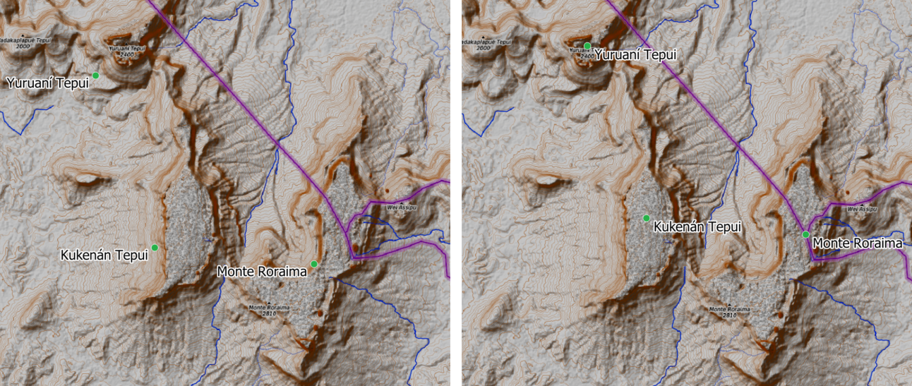
Fig. 24.103 Vector point layer (green dots) before (left), and after (right) an affine transformation (translation).
 Allows
features in-place modification
of point, line, and polygon features
Allows
features in-place modification
of point, line, and polygon features
See also
Parameters
Label |
Name |
Type |
Description |
|---|---|---|---|
Input layer |
|
[vector: geometry] |
Input vector layer |
Translation (x-axis) |
|
[numeric: double] Default: 0.0 |
Displacement to apply on the X axis. |
Translation (y-axis) |
|
[numeric: double] Default: 0.0 |
Displacement to apply on the Y axis. |
Translation (z-axis) |
|
[numeric: double] Default: 0.0 |
Displacement to apply on the Z axis. |
Translation (m-values) |
|
[numeric: double] Default: 0.0 |
Offset to apply on m values. |
Scale factor (x-axis) |
|
[numeric: double] Default: 1.0 |
Scaling value (expansion or contraction) to apply on the X axis. |
Scale factor (y-axis) |
|
[numeric: double] Default: 1.0 |
Scaling value (expansion or contraction) to apply on the Y axis. |
Scale factor (z-axis) |
|
[numeric: double] Default: 1.0 |
Scaling value (expansion or contraction) to apply on the Z axis. |
Scale factor (m-values) |
|
[numeric: double] Default: 1.0 |
Scaling value (expansion or contraction) to apply on m values. |
Rotation around z-axis (degrees counter-clockwise) |
|
[numeric: double] Default: 0.0 |
Angle of the rotation in degrees. |
Transformed |
|
[same as input] Default: |
Specify the output vector layer. One of:
The file encoding can also be changed here. |

Outputs
Label |
Name |
Type |
Description |
|---|---|---|---|
Transformed |
|
[same as input] |
Output (transformed) vector layer. |
Python code
Algorithm ID: native:affinetransform
import processing
processing.run("algorithm_id", {parameter_dictionary})
The algorithm id is displayed when you hover over the algorithm in the Processing Toolbox. The parameter dictionary provides the parameter NAMEs and values. See Using processing algorithms from the console for details on how to run processing algorithms from the Python console.
24.1.26.3. Aggregate
Takes a vector or table layer and creates a new layer by aggregating
features based on a group by expression.
Features for which group by expression returns the same value are
grouped together.
It is possible to group all source features together using constant
value in group by parameter, example: NULL.
It is also possible to group features by multiple fields using Array function, example: Array(“Field1”, “Field2”).
Geometries (if present) are combined into one multipart geometry for each group. Output attributes are computed depending on each given aggregate definition.
This algorithm allows to use the default aggregates functions of the QGIS Expression engine.
Note
This algorithm uses ellipsoid based measurements and respects the current ellipsoid settings.
See also
Parameters
Label |
Name |
Type |
Description |
|---|---|---|---|
Input layer |
|
[vector: any] |
Input vector layer |
Group by expression |
|
[tablefield: any] Default: ‘NULL’ |
Choose the grouping field. If NULL all features will be grouped. |
Aggregates |
|
[list] |
List of output layer field definitions. Example of a field definition: {‘aggregate’: ‘sum’, ‘delimiter’: ‘,’, ‘input’: ‘ $area’, ‘length’: 10, ‘name’: ‘totarea’, ‘precision’: 0, ‘type’: 6} By default, the list contains all the fields of the input layer. In the GUI, you can edit these fields and their definitions, and you can also:
For each of the fields you’d like to retrieve information from, you need to define the following:
|
Load fields from layer |
GUI only |
[vector: any] |
You can load fields from another layer and use them for the aggregation |
Aggregated |
|
[same as input] Default: |
Specify the output (aggregate) layer One of:
The file encoding can also be changed here. |


Outputs
Label |
Name |
Type |
Description |
|---|---|---|---|
Aggregated |
|
[same as input] |
Multigeometry vector layer with the aggregated values |
Python code
Algorithm ID: native:aggregate
import processing
processing.run("algorithm_id", {parameter_dictionary})
The algorithm id is displayed when you hover over the algorithm in the Processing Toolbox. The parameter dictionary provides the parameter NAMEs and values. See Using processing algorithms from the console for details on how to run processing algorithms from the Python console.
24.1.26.4. Approximate medial axis
Added in 4.0
Generates a simplified skeleton of polygon geometries by approximating their medial axis. The output is a line layer representing the central structure of each polygon, preserving main topology while ignoring small variations.
Z values are ignored; the medial axis is calculated from the 2D projection of input geometries.
Attention
Running this algorithm requires QGIS installed with SFCGAL >= 2.0 (see menu).
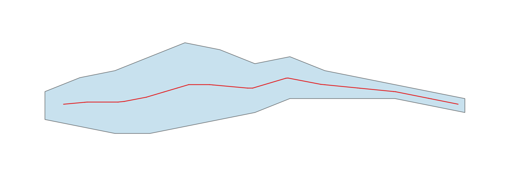
Fig. 24.104 Medial axis (red line) of a polygon layer
Parameters
Label |
Name |
Type |
Description |
|---|---|---|---|
Input layer |
|
[vector: polygon] |
Input polygon vector layer |
Extend endpoints to the polygon boundary
|
|
[boolean] Default: False |
Extends the medial axis so that its endpoints reach the boundary of the input polygon Attention Using this method requires QGIS installed with SFCGAL >= 2.3 (see menu). |
Medial axis |
|
[vector: line] Default: |
Specification of the output line layer. One of:
The file encoding can also be changed here. |
Outputs
Label |
Name |
Type |
Description |
|---|---|---|---|
Medial axis |
|
[vector: line] |
Output line layer containing the approximate medial axis |
Python code
Algorithm ID: native:approximatemedialaxis
import processing
processing.run("algorithm_id", {parameter_dictionary})
The algorithm id is displayed when you hover over the algorithm in the Processing Toolbox. The parameter dictionary provides the parameter NAMEs and values. See Using processing algorithms from the console for details on how to run processing algorithms from the Python console.
24.1.26.5. Boundary
Returns the closure of the combinatorial boundary of the input geometries (i.e. the topological boundary of the geometry).
Only for polygon and line layers.
For polygon geometries , the boundary consists of all the lines making up the rings of the polygon.
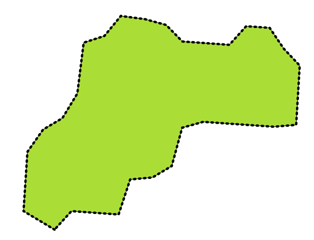
Fig. 24.105 Boundaries (black dashed line) of the source polygon layer
For lines geometries, the boundaries are their end points.
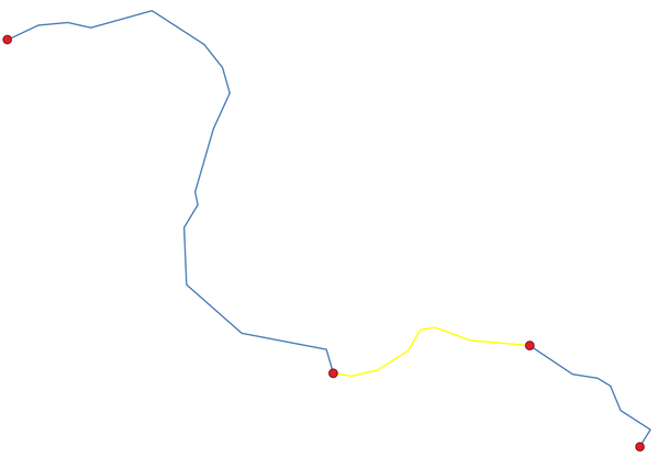
Fig. 24.106 Boundary layer (red points) for lines. In yellow a selected feature.
Parameters
Label |
Name |
Type |
Description |
|---|---|---|---|
Input layer |
|
[vector: line, polygon] |
Input line or polygon vector layer |
Boundary |
|
[vector: point, line] Default: |
Specify the output (boundary) layer. One of:
The file encoding can also be changed here. |
Outputs
Label |
Name |
Type |
Description |
|---|---|---|---|
Boundary |
|
[vector: point, line] |
Boundaries from the input layer (point for line, and line for polygon) |
Python code
Algorithm ID: native:boundary
import processing
processing.run("algorithm_id", {parameter_dictionary})
The algorithm id is displayed when you hover over the algorithm in the Processing Toolbox. The parameter dictionary provides the parameter NAMEs and values. See Using processing algorithms from the console for details on how to run processing algorithms from the Python console.
24.1.26.6. Bounding boxes
Calculates the bounding box (envelope) of each feature in an input layer. Polygon and line geometries are supported.
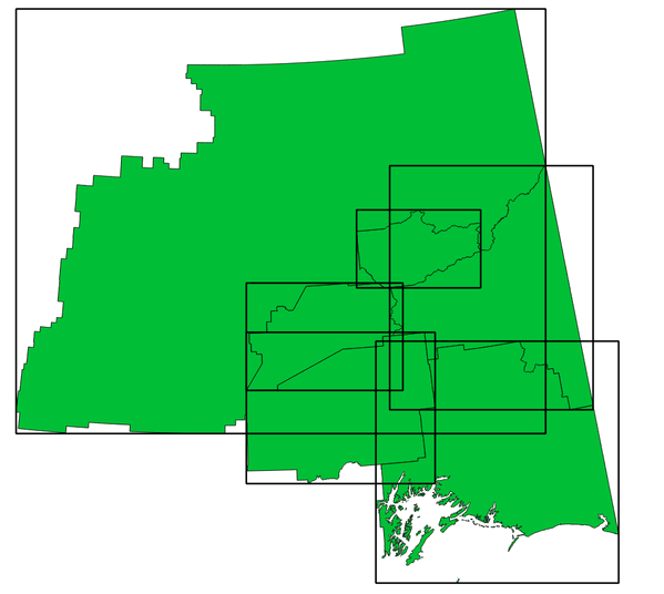
Fig. 24.107 Black lines represent the bounding boxes of each polygon feature
Allows
features in-place modification
of polygon features
See also
Parameters
Label |
Name |
Type |
Description |
|---|---|---|---|
Input layer |
|
[vector: line, polygon] |
Input line or polygon vector layer |
Bounds |
|
[vector: polygon] Default: |
Specify the output (bounding box) layer. One of:
The file encoding can also be changed here. |
Outputs
Label |
Name |
Type |
Description |
|---|---|---|---|
Bounds |
|
[vector: polygon] |
Bounding boxes of input layer.
Other than the input attributes, the output layer also contains following fields:
|
Python code
Algorithm ID: native:boundingboxes
import processing
processing.run("algorithm_id", {parameter_dictionary})
The algorithm id is displayed when you hover over the algorithm in the Processing Toolbox. The parameter dictionary provides the parameter NAMEs and values. See Using processing algorithms from the console for details on how to run processing algorithms from the Python console.
24.1.26.7. Buffer
Computes a buffer area for all the features in an input layer, using a fixed or data defined distance.
It is possible to use a negative distance for polygon input layers. In this case the buffer will result in a smaller polygon (setback).
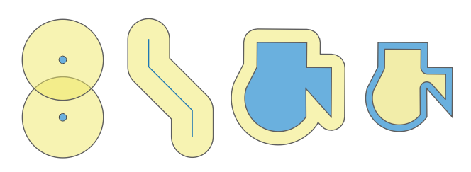
Fig. 24.108 Buffer (in yellow) of points, line, polygon with positive buffer, and polygon with negative buffer
Allows
features in-place modification
of polygon features
Default menu:
Warning
This algorithm may drop existing primary keys or FID values and regenerate them in output layers, depending on the input parameters.
See also
Variable distance buffer, Multi-ring buffer (constant distance), Variable width buffer (by M value)
Parameters
Basic parameters
Label |
Name |
Type |
Description |
|---|---|---|---|
Input layer |
|
[vector: geometry] |
Input vector layer |
Distance |
|
[numeric: double] Default: 10.0 |
Buffer distance (from the boundary of each feature). You can use the Data Defined button on the right to choose a field from which the radius will be calculated. This way you can have different radius for each feature. |
Segments |
|
[numeric: integer] Default: 5 |
Controls the number of line segments to use to approximate a quarter circle when creating rounded offsets. |
End cap style |
|
[enumeration] Default: 0 |
Controls how line endings are handled in the buffer. One of:
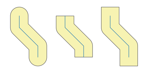
Fig. 24.109 Round, flat and square cap styles |
Join style |
|
[enumeration] Default: 0 |
Specifies whether round, miter or beveled joins should be used when offsetting corners in a line. Options are:
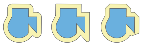
Fig. 24.110 Round, miter, and bevel join styles |
Miter limit |
|
[numeric: double] Default: 2.0 |
Sets the maximum distance from the offset geometry to use when creating a mitered join as a factor of the offset distance (only applicable for miter join styles). Minimum: 1.0 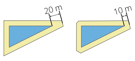
Fig. 24.111 A 10m buffer with a limit of 2 and a 10m buffer with a limit of 1 |
Dissolve result |
|
[boolean] Default: False |
Dissolve the final buffer. If 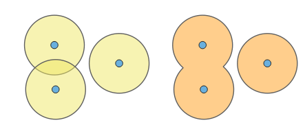
Fig. 24.112 Standard (three single part features - left), dissolved (1 multipart feature with 2 parts - right) |
Buffered |
|
[vector: polygon] Default: |
Specify the output (buffer) layer. One of:
The file encoding can also be changed here. |
Advanced parameters
Label |
Name |
Type |
Description |
|---|---|---|---|
Keep disjoint features separate
|
|
[boolean] Default: False |
If 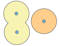
Fig. 24.113 Results in 2 single part features |
Outputs
Label |
Name |
Type |
Description |
|---|---|---|---|
Buffered |
|
[vector: polygon] |
Output (buffer) polygon layer |
Python code
Algorithm ID: native:buffer
import processing
processing.run("algorithm_id", {parameter_dictionary})
The algorithm id is displayed when you hover over the algorithm in the Processing Toolbox. The parameter dictionary provides the parameter NAMEs and values. See Using processing algorithms from the console for details on how to run processing algorithms from the Python console.
24.1.26.8. Centroids
Creates a new point layer, with points representing the centroids of the geometries of the input layer.
The centroid is a single point representing the barycenter (of all parts) of the feature, so it can be outside the feature borders. But can also be a point on each part of the feature.
The attributes of the points in the output layer are the same as for the original features.
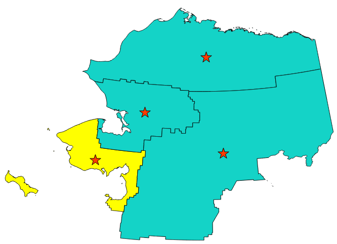
Fig. 24.114 The red stars represent the centroids of the features of the input layer.
Allows
features in-place modification
of point features
Default menu:
Warning
This algorithm may drop existing primary keys or FID values and regenerate them in output layers, depending on the input parameters.
See also
Parameters
Label |
Name |
Type |
Description |
|---|---|---|---|
Input layer |
|
[vector: geometry] |
Input vector layer |
Create centroid for each part |
|
[boolean] Default: False |
If True (checked), a centroid will be created for each part of the geometry |
Centroids |
|
[vector: point] Default: |
Specify the output (centroid) layer. One of:
The file encoding can also be changed here. |
Outputs
Label |
Name |
Type |
Description |
|---|---|---|---|
Centroids |
|
[vector: point] |
Output point vector layer (centroids) |
Python code
Algorithm ID: native:centroids
import processing
processing.run("algorithm_id", {parameter_dictionary})
The algorithm id is displayed when you hover over the algorithm in the Processing Toolbox. The parameter dictionary provides the parameter NAMEs and values. See Using processing algorithms from the console for details on how to run processing algorithms from the Python console.
24.1.26.9. Check validity
Performs a validity check on the geometries of a vector layer.
The geometries are classified in three groups (valid, invalid and error) and for each group, a vector layer with its features is generated:
The Valid output layer contains only the valid features (without topological errors).
The Invalid output layer contains all the invalid features found by the algorithm.
The Error output layer is a point layer that points to where the invalid features were found.
The attribute tables of the generated layers will contain some additional information (“message” for the error layer, “FID” and “_errors” for the invalid layer and only “FID” for the valid layer):
The attribute table of each generated vector layer will contain some additional information (number of errors found and types of error):
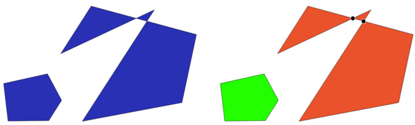
Fig. 24.115 Left: the input layer. Right: the valid layer (green), the invalid layer (orange)
Default menu:
See also
Parameters
Label |
Name |
Type |
Description |
|---|---|---|---|
Input layer |
|
[vector: geometry] |
Input vector layer |
Method |
|
[enumeration] Default: 2 |
Method to use to check validity. Options:
|
Ignore ring self intersection |
|
[boolean] Default: False |
Ignore self intersecting rings when checking for validity. |
Valid output |
|
[same as input] Default: |
Specify the vector layer to contain a copy of the valid features of the source layer. One of:
The file encoding can also be changed here. |
Invalid output |
|
[same as input] Default: |
Vector layer containing copy of the invalid features of
the source layer with the field
The file encoding can also be changed here. |
Error output |
|
[vector: point] Default: |
Point layer of the exact position of the validity
problems detected with the
The file encoding can also be changed here. |
Outputs
Label |
Name |
Type |
Description |
|---|---|---|---|
Count of errors |
|
[numeric: integer] |
The number of geometries that caused errors. |
Error output |
|
[vector: point] |
Point layer of the exact position of the validity
problems detected with the |
Count of invalid features |
|
[numeric: integer] |
The number of invalid geometries. |
Invalid output |
|
[same as input] |
Vector layer containing copy of the invalid features of
the source layer with the field |
Count of valid features |
|
[numeric: integer] |
The number of valid geometries. |
Valid output |
|
[same as input] |
Vector layer containing a copy of the valid features of the source layer. |
Python code
Algorithm ID: native:checkvalidity
import processing
processing.run("algorithm_id", {parameter_dictionary})
The algorithm id is displayed when you hover over the algorithm in the Processing Toolbox. The parameter dictionary provides the parameter NAMEs and values. See Using processing algorithms from the console for details on how to run processing algorithms from the Python console.
Types of error messages and their meanings
Geometry context |
GEOS validation and error message |
QGIS validation and error message |
|---|---|---|
Consecutive points on a line have the same coordinates 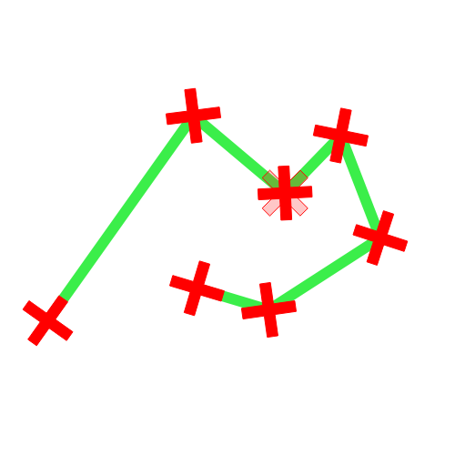
|
|
|
Segments of a line intersect each other 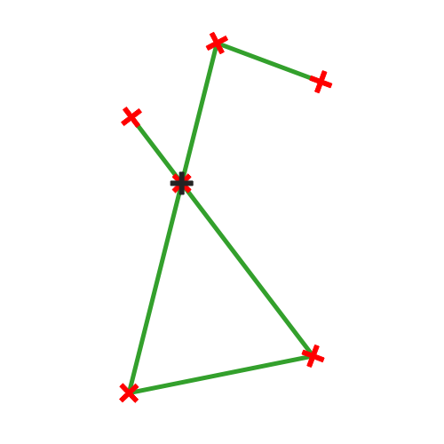
|
|
|
Polygon geometry touches itself and generates a ring 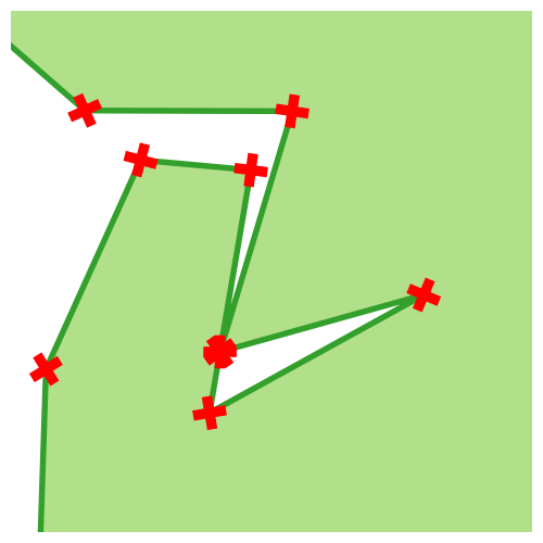
|
|
|
Two rings (exterior or interior) of a polygon geometry are identical 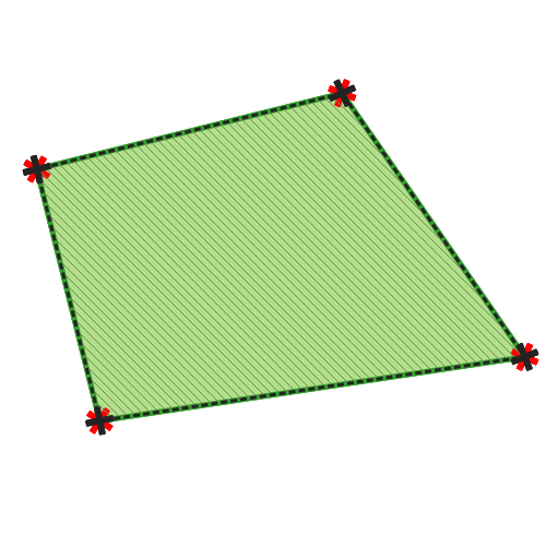
|
|
|
Geometry touches itself 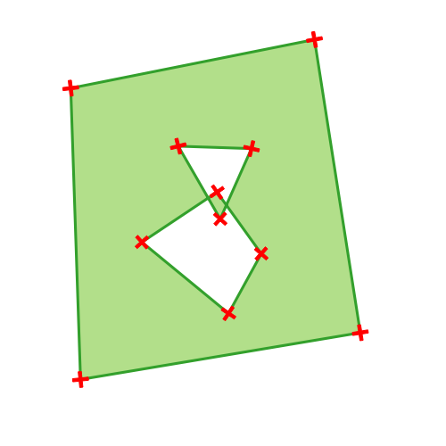
|
|
|
A polygon geometry is on top of another polygon geometry 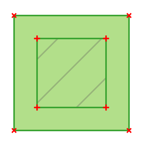
|
|
|
Part of a MultiPolygon geometry is within a hole of a MultiPolygon geometry 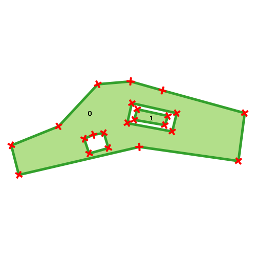
|
|
|
Point geometry does not have a proper coordinate pair. The coordinate pair does not contain a latitude value and a longitude value in that order. |
|

24.1.26.10. Collect geometries
Takes a vector layer and collects its geometries into new multipart geometries.
One or more attributes can be specified to collect only geometries belonging to the same class (having the same value for the specified attributes), alternatively all geometries can be collected.
All output geometries will be converted to multi geometries, even those with just a single part. This algorithm does not dissolve overlapping geometries - they will be collected together without modifying the shape of each geometry part.
See the ‘Promote to multipart’ or ‘Aggregate’ algorithms for alternative options.
Default menu:
Warning
This algorithm drops existing primary keys or FID values and regenerates them in output layers.
See also
Parameters
Label |
Name |
Type |
Description |
|---|---|---|---|
Input layer |
|
[vector: geometry] |
Input vector layer |
Unique ID fields |
|
[tablefield: any] [list] |
Choose one or more attributes to collect the geometries |
Collected |
|
[same as input] |
Vector layer with collected geometries |
Outputs
Label |
Name |
Type |
Description |
|---|---|---|---|
Collected |
|
[same as input] Default: |
Specify the output vector layer for the collected geometries. One of:
The file encoding can also be changed here. |
Python code
Algorithm ID: native:collect
import processing
processing.run("algorithm_id", {parameter_dictionary})
The algorithm id is displayed when you hover over the algorithm in the Processing Toolbox. The parameter dictionary provides the parameter NAMEs and values. See Using processing algorithms from the console for details on how to run processing algorithms from the Python console.
24.1.26.11. Concave hull (by feature)
Added in 3.44
Calculates the concave hull for each multipoint feature in an input layer. See the Concave hull (by layer) algorithm for a concave hull calculation which covers the whole layer.
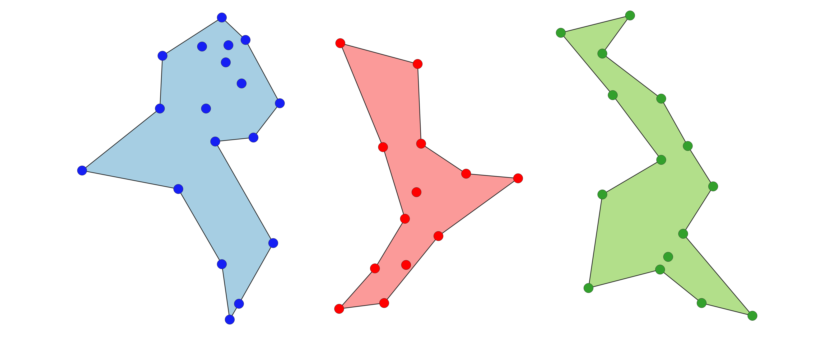
Fig. 24.116 Concave hulls by feature
See also
Parameters
Label |
Name |
Type |
Description |
|---|---|---|---|
Input layer |
|
[vector: point] |
Input vector layer with multipoint features |
Threshold |
|
[numeric: double] Default: 0.3 |
Number from 0 (maximum concave hull) to 1 (convex hull). 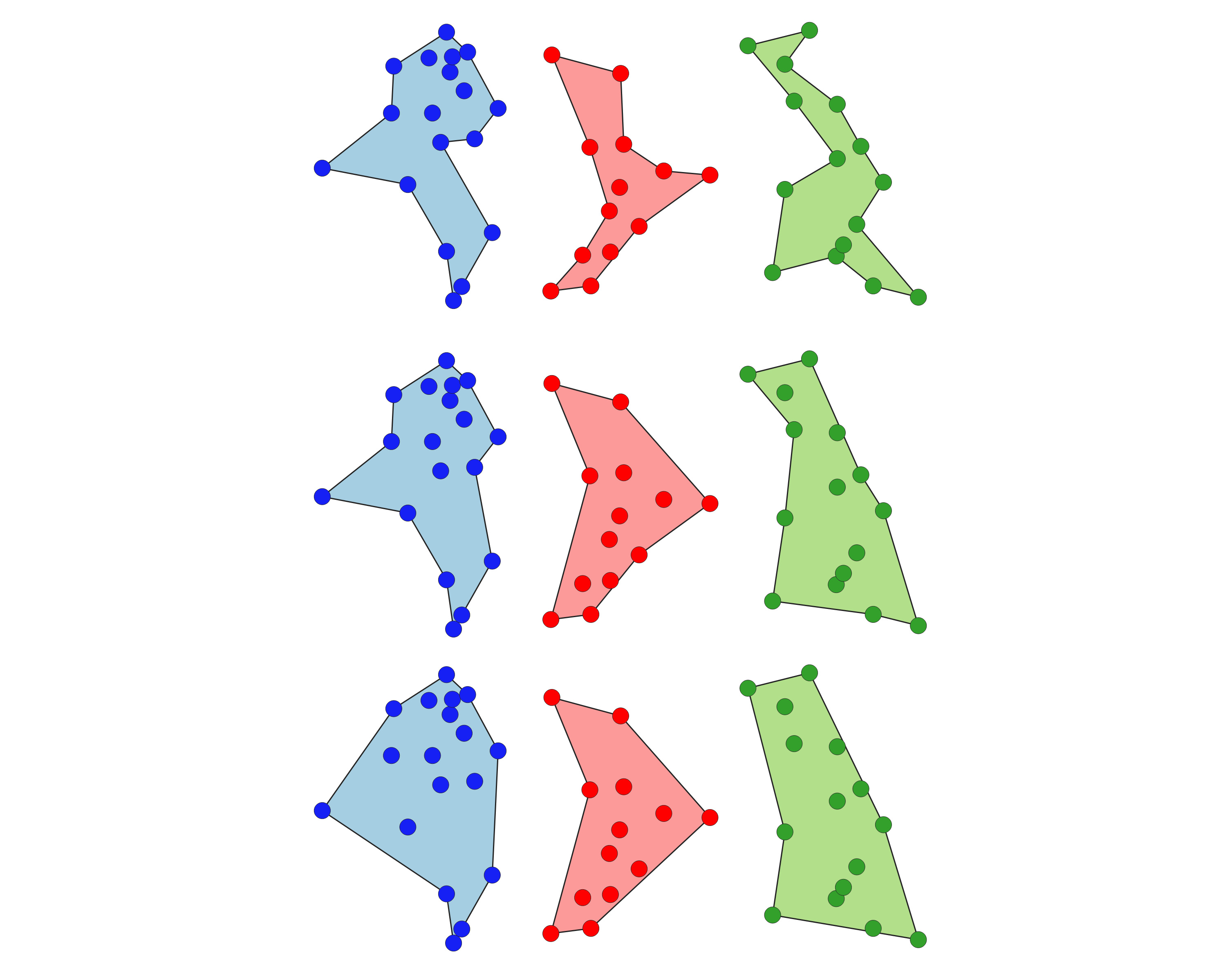
Fig. 24.117 Concave hulls with different thresholds (0.3, 0.6, 0.9) |
Allow holes |
|
[boolean] Default: True |
Choose whether to allow holes in the final concave hull |
Concave hulls |
|
[vector: polygon] Default: |
Specify the output vector layer. One of:
The file encoding can also be changed here. |
Outputs
Label |
Name |
Type |
Description |
|---|---|---|---|
Concave hulls |
|
[vector: polygon] |
The output vector layer with polygons covering individual multipoint features. Area and perimeter fields are added. |
Python code
Algorithm ID: native:concavehullbyfeature
import processing
processing.run("algorithm_id", {parameter_dictionary})
The algorithm id is displayed when you hover over the algorithm in the Processing Toolbox. The parameter dictionary provides the parameter NAMEs and values. See Using processing algorithms from the console for details on how to run processing algorithms from the Python console.
24.1.26.12. Concave hull (by layer)
Computes the concave hull covering all features from an input point layer. See the Concave hull (by feature) algorithm for a concave hull calculation which covers individual features from a layer.
See also
Parameters
Label |
Name |
Type |
Description |
|---|---|---|---|
Input layer |
|
[vector: point] |
Input point vector layer |
Threshold |
|
[numeric: double] Default: 0.3 |
Number from 0 (maximum concave hull) to 1 (convex hull). 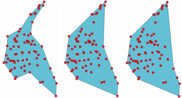
Fig. 24.118 Concave hulls with different thresholds (0.3, 0.6, 0.9) |
Allow holes |
|
[boolean] Default: True |
Choose whether to allow holes in the final concave hull |
Split multipart geometry into singlepart geometries |
|
[boolean] Default: False |
Check if you want to have singlepart geometries instead of multipart ones. |
Concave hull |
|
[vector: polygon] Default: |
Specify the output vector layer. One of:
The file encoding can also be changed here. |
Outputs
Label |
Name |
Type |
Description |
|---|---|---|---|
Concave hull |
|
[vector: polygon] |
The output vector layer covering all features from an input point layer. |
Python code
Algorithm ID: native:concavehull
import processing
processing.run("algorithm_id", {parameter_dictionary})
The algorithm id is displayed when you hover over the algorithm in the Processing Toolbox. The parameter dictionary provides the parameter NAMEs and values. See Using processing algorithms from the console for details on how to run processing algorithms from the Python console.
24.1.26.13. Convert geometry type
Generates a new layer based on an existing one, with a different type of geometry.
The attribute table of the output layer is the same as the one of the input layer.
Not all conversions are possible. For instance, a line layer can be converted to a point layer, but a point layer cannot be converted to a line layer.
See also
Polygonize, Lines to polygons, Polygons to lines, Points to path
Parameters
Label |
Name |
Type |
Description |
|---|---|---|---|
Input layer |
|
[vector: geometry] |
Input vector layer |
New geometry type |
|
[enumeration] Default: 0 |
Geometry type to apply to the output features. One of:
|
Converted |
|
[vector: geometry] Default: |
Specify the output vector layer. One of:
The file encoding can also be changed here. |
Outputs
Label |
Name |
Type |
Description |
|---|---|---|---|
Converted |
|
[vector: geometry] |
Output vector layer - the type depends on the parameters |
Python code
Algorithm ID: native:convertgeometrytype
import processing
processing.run("algorithm_id", {parameter_dictionary})
The algorithm id is displayed when you hover over the algorithm in the Processing Toolbox. The parameter dictionary provides the parameter NAMEs and values. See Using processing algorithms from the console for details on how to run processing algorithms from the Python console.
24.1.26.14. Convert to curved geometries
Converts a geometry into its curved geometry equivalent.
Already curved geometries will be retained without change.
Allows
features in-place modification
of line and polygon features
Parameters
Label |
Name |
Type |
Description |
|---|---|---|---|
Input layer |
|
[vector: line or polygon] |
Input vector layer |
Maximum distance tolerance |
|
[numeric: double] Default: 0.000001 |
The maximum distance allowed between the original location of vertices and where they would fall on the converted curved geometries |
Maximum angle tolerance |
|
[numeric: double] Default: 0.000001 |
Segments are considered as suitable for replacing with an arc if the points are all regularly spaced on the candidate arc. This parameter specifies the maximum angular deviation (in degrees) allowed when testing for regular point spacing. Between 0 and 45°. |
Curves |
|
[vector: compoundcurve or curvepolygon] Default: |
Specify the output vector layer. One of:
The file encoding can also be changed here. |
Outputs
Label |
Name |
Type |
Description |
|---|---|---|---|
Curves |
|
[vector: compoundcurve or curvepolygon] |
Output vector layer with curved geometries |
Python code
Algorithm ID: native:converttocurves
import processing
processing.run("algorithm_id", {parameter_dictionary})
The algorithm id is displayed when you hover over the algorithm in the Processing Toolbox. The parameter dictionary provides the parameter NAMEs and values. See Using processing algorithms from the console for details on how to run processing algorithms from the Python console.
24.1.26.15. Convex hull
Calculates the convex hull for each feature in an input layer.
See the ‘Minimum bounding geometry’ algorithm for a convex hull calculation which covers the whole layer or grouped subsets of features.
Fig. 24.119 Black lines identify the convex hull for each layer feature
Allows
features in-place modification
of polygon features
Default menu:
Parameters
Label |
Name |
Type |
Description |
|---|---|---|---|
Input layer |
|
[vector: geometry] |
Input vector layer |
Convex hull |
|
[vector: polygon] Default: |
Specify the output vector layer. One of:
The file encoding can also be changed here. |
Outputs
Label |
Name |
Type |
Description |
|---|---|---|---|
Convex hull |
|
[vector: polygon] |
The output (convex hull) vector layer.
Other than the input attributes, the output layer also contains the following fields:
|
Python code
Algorithm ID: native:convexhull
import processing
processing.run("algorithm_id", {parameter_dictionary})
The algorithm id is displayed when you hover over the algorithm in the Processing Toolbox. The parameter dictionary provides the parameter NAMEs and values. See Using processing algorithms from the console for details on how to run processing algorithms from the Python console.
24.1.26.16. Create wedge buffers
Creates wedge shaped buffers from input points.
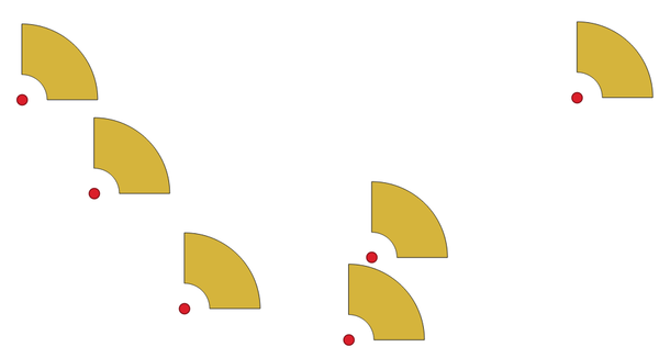
Fig. 24.120 Wedge buffers
The native output from this algorithm are CurvePolygon geometries, but these may be automatically segmentized to Polygons depending on the output format.
Parameters
Label |
Name |
Type |
Description |
|---|---|---|---|
Input layer |
|
[vector: point] |
Input point vector layer |
Azimuth (degrees from North) |
|
[numeric: double] Default: 0.0 |
Angle (in degrees) as the middle value of the wedge |
Wedge width (in degrees) |
|
[numeric: double] Default: 45.0 |
Width (in degrees) of the buffer. The wedge will extend to half of the angular width either side of the azimuth direction. 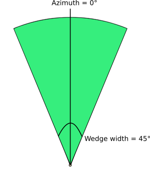
Fig. 24.121 Azimuth and width values of the wedge buffer |
Outer radius |
|
[numeric: double] Default: 1.0 |
The outer size (length) of the wedge: the size is meant from the source point to the edge of the wedge shape. |
Inner radius Optional |
|
[numeric: double] Default: 0.0 |
Inner radius value. If 0 the wedge will begin from the source point. |
Buffers |
|
[vector: polygon] Default: |
Specify the output vector layer. One of:
The file encoding can also be changed here. |
Outputs
Label |
Name |
Type |
Description |
|---|---|---|---|
Buffers |
|
[vector: polygon] |
The output (wedge buffer) vector layer |
Python code
Algorithm ID: native:wedgebuffers
import processing
processing.run("algorithm_id", {parameter_dictionary})
The algorithm id is displayed when you hover over the algorithm in the Processing Toolbox. The parameter dictionary provides the parameter NAMEs and values. See Using processing algorithms from the console for details on how to run processing algorithms from the Python console.
24.1.26.17. Delaunay triangulation
Creates a polygon layer with the Delaunay triangulation corresponding to the input point layer.
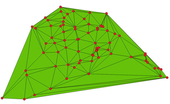
Fig. 24.122 Delaunay triangulation on points
Default menu:
Parameters
Label |
Name |
Type |
Description |
|---|---|---|---|
Input layer |
|
[vector: point] |
Input point vector layer |
Tolerance Optional
|
|
[numeric: double] Default: 0.0 |
Specifies an optional snapping tolerance which can be used to improve the robustness of the triangulation. |
Add point IDs to output
|
|
[boolean] Default: True |
Specifies whether fields storing involved point features ID should be added to the output.
If False, an |
Delaunay triangulation |
|
[vector: polygon] Default: |
Specify the output vector layer. One of:
The file encoding can also be changed here. |
Outputs
Label |
Name |
Type |
Description |
|---|---|---|---|
Delaunay triangulation |
|
[vector: polygon] |
The output (Delaunay triangulation) vector layer |
Python code
Algorithm ID: native:delaunaytriangulation
import processing
processing.run("algorithm_id", {parameter_dictionary})
The algorithm id is displayed when you hover over the algorithm in the Processing Toolbox. The parameter dictionary provides the parameter NAMEs and values. See Using processing algorithms from the console for details on how to run processing algorithms from the Python console.
24.1.26.18. Delete holes
Takes a polygon layer and removes holes in polygons. It creates a new vector layer in which polygons with holes have been replaced by polygons with only their external ring. Attributes are not modified.
An optional minimum area parameter allows removing only holes which
are smaller than a specified area threshold. Leaving this parameter at
0.0 results in all holes being removed.
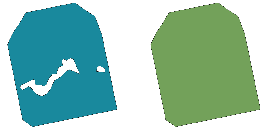
Fig. 24.123 Before and after the cleaning
Allows
features in-place modification
of polygon features
See also
qgisfixgeometryhole
Parameters
Label |
Name |
Type |
Description |
|---|---|---|---|
Input layer |
|
[vector: polygon] |
Input polygon vector layer |
Remove holes with area less than Optional |
|
[numeric: double] Default: 0.0 |
Only holes with an area less than this threshold will be
deleted.
With a value of |
Cleaned |
|
[same as input] Default: |
Specify the output vector layer. One of:
The file encoding can also be changed here. |
Outputs
Label |
Name |
Type |
Description |
|---|---|---|---|
Cleaned |
|
[same as input] |
The output (cleaned) vector layer |
Python code
Algorithm ID: native:deleteholes
import processing
processing.run("algorithm_id", {parameter_dictionary})
The algorithm id is displayed when you hover over the algorithm in the Processing Toolbox. The parameter dictionary provides the parameter NAMEs and values. See Using processing algorithms from the console for details on how to run processing algorithms from the Python console.
24.1.26.19. Densify by count
Takes a polygon or line layer and generates a new one in which the geometries have a larger number of vertices than the original one.
If the geometries have Z or M values present then these will be linearly interpolated at the added vertices.
The number of new vertices to add to each segment is specified as an input parameter.
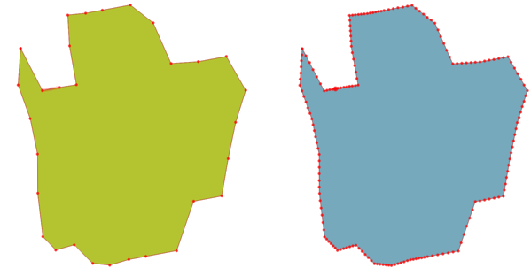
Fig. 24.124 Red points show the vertices before and after the densify
Allows
features in-place modification
of line and polygon features
Default menu:
See also
Parameters
Label |
Name |
Type |
Description |
|---|---|---|---|
Input layer |
|
[vector: line, polygon] |
Input line or polygon vector layer |
Vertices to add |
|
[numeric: integer] Default: 1 |
Number of vertices to add to each segment |
Densified |
|
[same as input] Default: |
Specify the output vector layer. One of:
The file encoding can also be changed here. |
Outputs
Label |
Name |
Type |
Description |
|---|---|---|---|
Densified |
|
[same as input] |
The output (densified) vector layer |
Python code
Algorithm ID: native:densifygeometries
import processing
processing.run("algorithm_id", {parameter_dictionary})
The algorithm id is displayed when you hover over the algorithm in the Processing Toolbox. The parameter dictionary provides the parameter NAMEs and values. See Using processing algorithms from the console for details on how to run processing algorithms from the Python console.
24.1.26.20. Densify by interval
Takes a polygon or line layer and generates a new one in which the geometries have a larger number of vertices than the original one.
The geometries are densified by adding regularly placed extra vertices inside each segment so that the maximum distance between any two vertices does not exceed the specified distance.
If the geometries have Z or M values present then these will be linearly interpolated at the added vertices.
Example
Specifying a distance of 3 would cause the segment
[0 0] -> [10 0] to be converted to
[0 0] -> [2.5 0] -> [5 0] -> [7.5 0] -> [10 0],
since 3 extra vertices are required on the segment and spacing these
at 2.5 increments allows them to be evenly spaced over the segment.
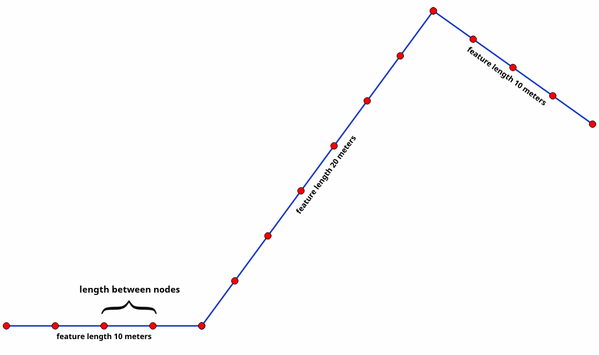
Fig. 24.125 Densify geometry at a given interval
Allows
features in-place modification
of line and polygon features
See also
Parameters
Label |
Name |
Type |
Description |
|---|---|---|---|
Input layer |
|
[vector: line, polygon] |
Input line or polygon vector layer |
Interval between vertices to add |
|
[numeric: double] Default: 1.0 |
Maximum distance between two consecutive vertices |
Densified |
|
[same as input] Default: |
Specify the output vector layer. One of:
The file encoding can also be changed here. |
Outputs
Label |
Name |
Type |
Description |
|---|---|---|---|
Densified |
|
[same as input] |
The output (densified) vector layer |
Python code
Algorithm ID: native:densifygeometriesgivenaninterval
import processing
processing.run("algorithm_id", {parameter_dictionary})
The algorithm id is displayed when you hover over the algorithm in the Processing Toolbox. The parameter dictionary provides the parameter NAMEs and values. See Using processing algorithms from the console for details on how to run processing algorithms from the Python console.
24.1.26.21. Dissolve
Takes a vector layer and combines its features into new features. One or more attributes can be specified to dissolve features belonging to the same class (having the same value for the specified attributes), alternatively all features can be dissolved to a single feature.
All output geometries will be converted to multi geometries. In case the input is a polygon layer, common boundaries of adjacent polygons being dissolved will get erased. If enabled, the optional “Keep disjoint features separate” setting will cause features and parts that do not overlap or touch to be exported as separate features (instead of parts of a single multipart feature).
The resulting attribute table will have the same fields as the input layer. The values in the output layer’s fields are the ones of the first input feature that happens to be processed.
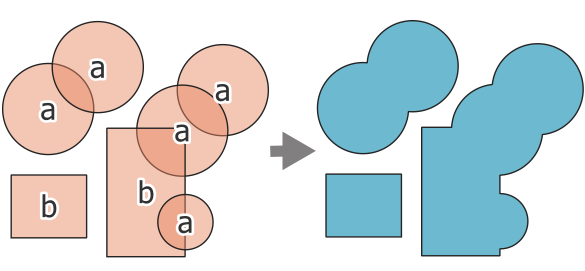
Fig. 24.126 Dissolving a layer into a single multipart feature
Default menu:
Warning
This algorithm drops existing primary keys or FID values and regenerates them in output layers.
See also
Parameters
Basic parameters
Label |
Name |
Type |
Description |
|---|---|---|---|
Input layer |
|
[vector: geometry] |
Input vector layer |
Dissolve field(s) Optional |
|
[tablefield: any] [list] Default: [] |
Features having the same value for the selected field(s) will be replaced with a single one and their geometries are merged. If no field is provided then all the features are dissolved, resulting in a single (multipart) feature. 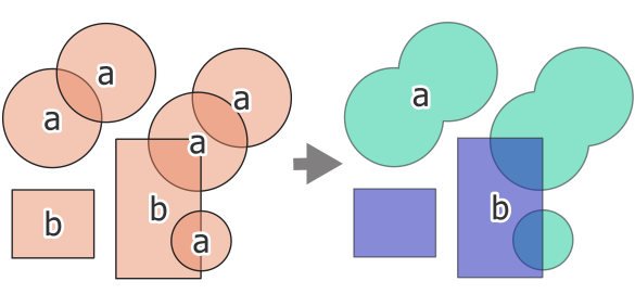
Fig. 24.127 Dissolve the polygon layer on a common attribute (2 multipart features) |
Dissolved |
|
[same as input] Default: |
Specify the output vector layer. One of:
The file encoding can also be changed here. |
Advanced parameters
Label |
Name |
Type |
Description |
|---|---|---|---|
Keep disjoint features separate |
|
[boolean] Default: False |
Parts of dissolved features are exported as separate features (instead of parts of a multipart feature). 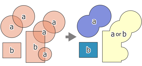
Fig. 24.128 source (left), dissolve all (3 distinct features - right) 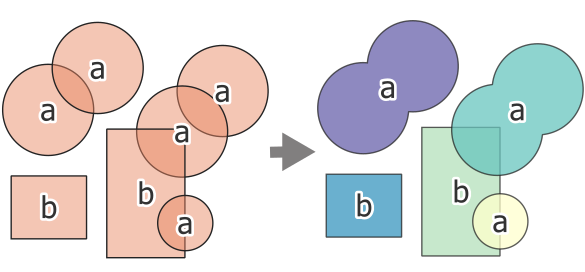
Fig. 24.129 source (left), dissolve on field (5 distinct features - right) |
Outputs
Label |
Name |
Type |
Description |
|---|---|---|---|
Dissolved |
|
[same as input] |
The output vector layer with dissolved geometries |
Python code
Algorithm ID: native:dissolve
import processing
processing.run("algorithm_id", {parameter_dictionary})
The algorithm id is displayed when you hover over the algorithm in the Processing Toolbox. The parameter dictionary provides the parameter NAMEs and values. See Using processing algorithms from the console for details on how to run processing algorithms from the Python console.
24.1.26.22. Drape (set Z value from raster)
Uses values sampled from a band within a raster layer to set the Z value for every overlapping vertex in the feature geometry. The raster values can optionally be scaled by a preset amount.
If Z values already exist in the layer, they will be overwritten with the new value. If no Z values exist, the geometry will be upgraded to include the Z dimension.
Allows
features in-place modification
of point, line, and polygon features with Z enabled
See also
Parameters
Label |
Name |
Type |
Description |
|---|---|---|---|
Input layer |
|
[vector: geometry] |
Input vector layer |
Raster layer |
|
[raster] |
Raster layer with Z values |
Band number |
|
[raster band] Default: 1 |
The raster band to take the Z values from |
Value for NoData or non-intersecting vertices |
|
[numeric: double] Default: 0.0 |
Value to use in case the vertex does not intersect (a valid pixel of) the raster |
Scale factor |
|
[numeric: double] Default: 1.0 |
Scaling value: the band values are multiplied by this value. |
Offset |
|
[numeric: double] Default: 0.0 |
Offset value: it is algebraically added to the band values after applying the “Scale factor”. |
Updated |
|
[same as input] Default: |
Specify the output vector layer (with Z values from the raster layer). One of:
The file encoding can also be changed here. |
Outputs
Label |
Name |
Type |
Description |
|---|---|---|---|
Updated |
|
[same as input] |
The output vector layer with Z values from the raster layer |
Python code
Algorithm ID: native:setzfromraster
import processing
processing.run("algorithm_id", {parameter_dictionary})
The algorithm id is displayed when you hover over the algorithm in the Processing Toolbox. The parameter dictionary provides the parameter NAMEs and values. See Using processing algorithms from the console for details on how to run processing algorithms from the Python console.
24.1.26.23. Drop M/Z values
Removes M (measure) or Z (altitude) values from input geometries.
See also
Parameters
Label |
Name |
Type |
Description |
|---|---|---|---|
Input layer |
|
[vector: geometry] |
Input vector layer with M or Z values |
Drop M Values |
|
[boolean] Default: False |
Removes the M values from the geometries |
Drop Z Values |
|
[boolean] Default: False |
Removes the Z values from the geometries |
Z/M Dropped |
|
[same as input] Default: |
Specify the output vector layer. One of:
The file encoding can also be changed here. |
Outputs
Label |
Name |
Type |
Description |
|---|---|---|---|
Z/M Dropped |
|
[same as input] |
The output vector layer (identical to the input layer, except that the M and/or Z dimensions have been removed from the geometries). |
Python code
Algorithm ID: native:dropmzvalues
import processing
processing.run("algorithm_id", {parameter_dictionary})
The algorithm id is displayed when you hover over the algorithm in the Processing Toolbox. The parameter dictionary provides the parameter NAMEs and values. See Using processing algorithms from the console for details on how to run processing algorithms from the Python console.
24.1.26.24. Eliminate selected polygons
Combines selected polygons of the input layer with certain adjacent polygons by erasing their common boundary. The adjacent polygon can be either the one with the largest or smallest area or the one sharing the largest common boundary with the polygon to be eliminated.
Eliminate is normally used to get rid of sliver polygons, i.e. tiny polygons that are a result of polygon intersection processes where boundaries of the inputs are similar but not identical.
Default menu:
See also
Parameters
Label |
Name |
Type |
Description |
|---|---|---|---|
Input layer |
|
[vector: polygon] |
Input polygon vector layer |
Merge selection with the neighboring polygon with the |
|
[enumeration] Default: Not set |
Choose the parameter to use in order to get rid of the selected polygons:
|
Eliminated |
|
[vector: polygon] Default: |
Specify the output vector layer. One of:
The file encoding can also be changed here. |
Outputs
Label |
Name |
Type |
Description |
|---|---|---|---|
Eliminated |
|
[vector: polygon] |
The output polygon vector layer. |
Python code
Algorithm ID: qgis:eliminateselectedpolygons
import processing
processing.run("algorithm_id", {parameter_dictionary})
The algorithm id is displayed when you hover over the algorithm in the Processing Toolbox. The parameter dictionary provides the parameter NAMEs and values. See Using processing algorithms from the console for details on how to run processing algorithms from the Python console.
24.1.26.25. Explode lines
Takes a lines layer and creates a new one in which each line layer is replaced by a set of lines representing the segments in the original line.
Each line in the resulting layer contains only a start and an end point, with no intermediate vertices between them.
If the input layer consists of CircularStrings or CompoundCurves, the output layer will be of the same type and contain only single curve segments.
Note
This algorithm drops existing primary keys or FID values and regenerates them in output layers.
This algorithm does not require valid geometries as input.
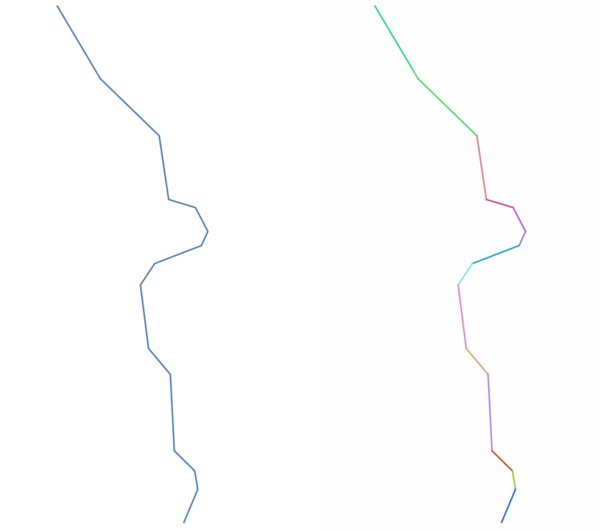
Fig. 24.130 The original line layer and the exploded one
Allows
features in-place modification
of line features
See also
Parameters
Label |
Name |
Type |
Description |
|---|---|---|---|
Input layer |
|
[vector: line] |
Input line vector layer |
Exploded |
|
[vector: line] Default: |
Specify the output vector layer. One of:
The file encoding can also be changed here. |
Outputs
Label |
Name |
Type |
Description |
|---|---|---|---|
Exploded |
|
[vector: line] |
The output line vector layer with features representing each segment of the input layer. |
Python code
Algorithm ID: native:explodelines
import processing
processing.run("algorithm_id", {parameter_dictionary})
The algorithm id is displayed when you hover over the algorithm in the Processing Toolbox. The parameter dictionary provides the parameter NAMEs and values. See Using processing algorithms from the console for details on how to run processing algorithms from the Python console.
24.1.26.26. Extend lines
Extends line geometry by a specified amount at the start and end of the line.
Lines are extended using the bearing of the first and last segment in the line.
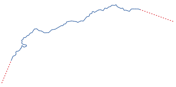
Fig. 24.131 The red dashes represent the initial and final extension of the original layer
Allows
features in-place modification
of line features
See also
Parameters
Label |
Name |
Type |
Description |
|---|---|---|---|
Input layer |
|
[vector: line] |
Input line vector layer |
Start distance |
|
[numeric: double] Default: 0.0 |
Distance by which to extend the first segment of the line (starting point) |
End distance |
|
[numeric: double] Default: 0.0 |
Distance by which to extend the last segment of the line (ending point) |
Extended |
|
[vector: line] Default: |
Specify the output vector layer. One of:
The file encoding can also be changed here. |
Outputs
Label |
Name |
Type |
Description |
|---|---|---|---|
Extended |
|
[vector: line] |
The output (extended) line vector layer. |
Python code
Algorithm ID: native:extendlines
import processing
processing.run("algorithm_id", {parameter_dictionary})
The algorithm id is displayed when you hover over the algorithm in the Processing Toolbox. The parameter dictionary provides the parameter NAMEs and values. See Using processing algorithms from the console for details on how to run processing algorithms from the Python console.
24.1.26.27. Extract M values
Extracts M values from geometries into feature attributes.
By default only the M value from the first vertex of each feature is extracted, however the algorithm can optionally calculate statistics on all of the geometry’s M values, including sum, mean, minimum and maximum.
See also
Parameters
Label |
Name |
Type |
Description |
|---|---|---|---|
Input layer |
|
[vector: geometry] |
Input vector layer |
Summaries to calculate |
|
[enumeration] Default: [0] |
Statistics on the M values of a geometry. One or more of:
|
Output column prefix |
|
[string] Default: ‘m_’ |
The prefix for the output (M) column |
Extracted |
|
[same as input] Default: |
Specify the output layer. One of:
The file encoding can also be changed here. |
Outputs
Label |
Name |
Type |
Description |
|---|---|---|---|
Extracted |
|
[same as input] |
The output vector layer (with M values) |
Python code
Algorithm ID: native:extractmvalues
import processing
processing.run("algorithm_id", {parameter_dictionary})
The algorithm id is displayed when you hover over the algorithm in the Processing Toolbox. The parameter dictionary provides the parameter NAMEs and values. See Using processing algorithms from the console for details on how to run processing algorithms from the Python console.
24.1.26.28. Extract specific vertices
Takes a vector layer and generates a point layer with points representing specific vertices in the input geometries.
For instance, this algorithm can be used to extract the first or last vertices in the geometry. The attributes associated to each point are the same ones associated to the feature that the vertex belongs to.
The vertex indices parameter accepts a comma separated string specifying the indices of the vertices to extract. The first vertex corresponds to an index of 0, the second vertex has an index of 1, etc. Negative indices can be used to find vertices at the end of the geometry, e.g., an index of -1 corresponds to the last vertex, -2 corresponds to the second last vertex, etc.
Additional fields are added to the vertices indicating the specific vertex position (e.g., 0, -1, etc), the original vertex index, the vertex’s part and its index within the part (as well as its ring for polygons), distance along the original geometry and bisector angle of vertex for the original geometry.
Allows
features in-place modification
of point features
Warning
This algorithm drops existing primary keys or FID values and regenerates them in output layers.
Parameters
Label |
Name |
Type |
Description |
|---|---|---|---|
Input layer |
|
[vector: geometry] |
Input vector layer |
Vertex indices |
|
[string] Default: ‘0’ |
Comma-separated string of the indices of the vertices to extract. |
Vertices |
|
[vector: point] Default: |
Specify the output vector layer. One of:
The file encoding can also be changed here. |
Outputs
Label |
Name |
Type |
Description |
|---|---|---|---|
Vertices |
|
[vector: point] |
The output (point) vector layer containing the specified vertices from the input layer geometries. Other than the input attributes, the output layer also contains the following fields:
|
Python code
Algorithm ID: native:extractspecificvertices
import processing
processing.run("algorithm_id", {parameter_dictionary})
The algorithm id is displayed when you hover over the algorithm in the Processing Toolbox. The parameter dictionary provides the parameter NAMEs and values. See Using processing algorithms from the console for details on how to run processing algorithms from the Python console.
24.1.26.29. Extract vertices
Takes a vector layer and generates a point layer with points representing the vertices in the input geometries.
The attributes associated to each point are the same ones associated to the feature that the vertex belongs to.
Additional fields are added to the vertices indicating the vertex index (beginning at 0), the feature’s part and its index within the part (as well as its ring for polygons), distance along original geometry and bisector angle of vertex for original geometry.
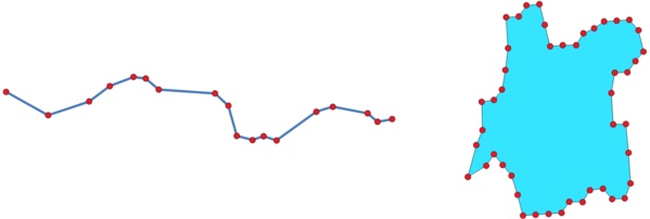
Fig. 24.132 Vertices extracted for line and polygon layer
Allows
features in-place modification
of point features
Default menu:
Warning
This algorithm drops existing primary keys or FID values and regenerates them in output layers.
Parameters
Label |
Name |
Type |
Description |
|---|---|---|---|
Input layer |
|
[vector: geometry] |
Input vector layer |
Vertices |
|
[vector: point] Default: |
Specify the output vector layer. One of:
The file encoding can also be changed here. |
Outputs
Label |
Name |
Type |
Description |
|---|---|---|---|
Vertices |
|
[vector: point] |
The output (point) vector layer containing the vertices from the input layer geometries. Other than the input attributes, the output layer also contains the following fields:
|
Python code
Algorithm ID: native:extractvertices
import processing
processing.run("algorithm_id", {parameter_dictionary})
The algorithm id is displayed when you hover over the algorithm in the Processing Toolbox. The parameter dictionary provides the parameter NAMEs and values. See Using processing algorithms from the console for details on how to run processing algorithms from the Python console.
24.1.26.30. Extract Z values
Extracts Z values from geometries into feature attributes.
By default only the Z value from the first vertex of each feature is extracted, however the algorithm can optionally calculate statistics on all of the geometry’s Z values, including sum, mean, minimum and maximum.
See also
Parameters
Label |
Name |
Type |
Description |
|---|---|---|---|
Input layer |
|
[vector: geometry] |
Input vector layer |
Summaries to calculate |
|
[enumeration] Default: [0] |
Statistics on the Z values of a geometry. One or more of:
|
Output column prefix |
|
[string] Default: ‘z_’ |
The prefix for the output (Z) column |
Extracted |
|
[same as input] Default: |
Specify the output layer. One of:
The file encoding can also be changed here. |
Outputs
Label |
Name |
Type |
Description |
|---|---|---|---|
Extracted |
|
[same as input] |
The output vector layer (with Z values) |
Python code
Algorithm ID: native:extractzvalues
import processing
processing.run("algorithm_id", {parameter_dictionary})
The algorithm id is displayed when you hover over the algorithm in the Processing Toolbox. The parameter dictionary provides the parameter NAMEs and values. See Using processing algorithms from the console for details on how to run processing algorithms from the Python console.
24.1.26.31. Extrude
Added in 4.2
Generates 3D geometries by extruding 2D polygon features along a specified direction.
Each feature is displaced according to the X, Y, and Z extrusion parameters: X and Y control the horizontal displacement, while Z controls the vertical elevation. Setting only the Z parameter produces vertical extrusions, whereas combining X, Y, and Z allows the creation of non-vertical extrusions. Negative values are supported, enabling extrusions in the opposite direction.
If the input features already carry Z values, those values are preserved and used as the base elevation of the extruded geometry.
For MultiPolygon geometries, each part is extruded separately, producing one output feature per part.
Output geometries are of type PolyhedralSurfaceZ, representing the extruded surface of each input feature.
Attention
Running this algorithm requires QGIS installed with SFCGAL >= 2.0 (see menu).
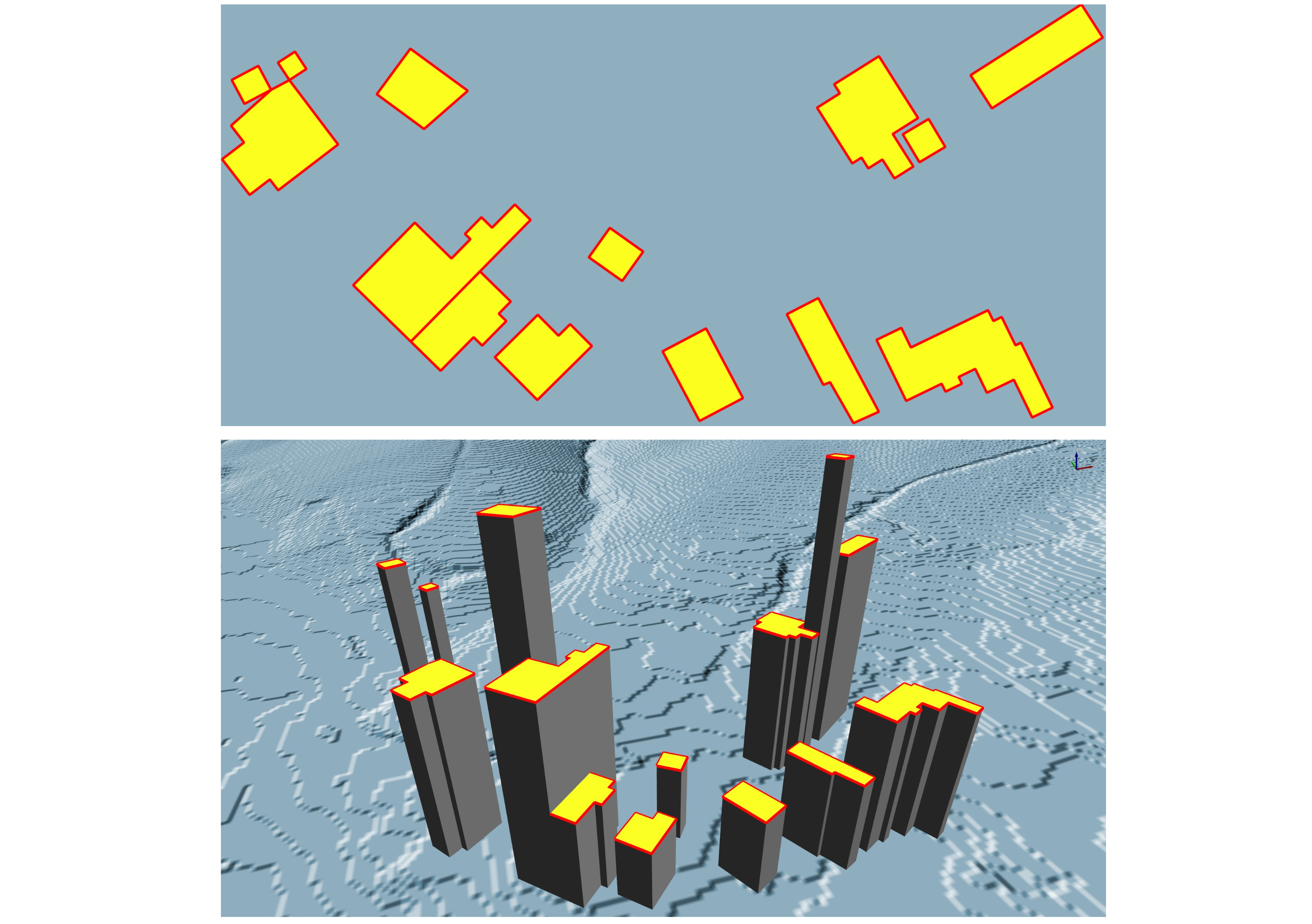
Fig. 24.133 The left image shows a 2D polygon, while the right image shows the polygon extruded along the Z direction.
Parameters
Label |
Name |
Type |
Description |
|---|---|---|---|
Input layer |
|
[vector: polygon] |
Input vector layer |
Extrusion (x-axis) |
|
[numeric: double] Default: 0 |
Specify the extrusion value along the X-axis |
Extrusion (y-axis) |
|
[numeric: double] Default: 0 |
Specify the extrusion value along the Y-axis |
Extrusion (z-axis) |
|
[numeric: double] Default: 0 |
Specify the extrusion value along the Z-axis |
Extrusion |
|
[vector: 3D polygon] Default: |
Specify the output vector layer. One of:
The file encoding can also be changed here. |
Outputs
Label |
Name |
Type |
Description |
|---|---|---|---|
Extrusion |
|
[vector: 3D polygon] |
The output layer containing the extruded polygon features. |
Python code
Algorithm ID: native:extrude
import processing
processing.run("algorithm_id", {parameter_dictionary})
The algorithm id is displayed when you hover over the algorithm in the Processing Toolbox. The parameter dictionary provides the parameter NAMEs and values. See Using processing algorithms from the console for details on how to run processing algorithms from the Python console.
24.1.26.32. Filter vertices by M value
Filters away vertices based on their M value, returning geometries with only vertex points that have a M value greater than or equal to the specified minimum value and/or less than or equal to the maximum value.
If the minimum value is not specified then only the maximum value is tested, and similarly if the maximum value is not specified then only the minimum value is tested.
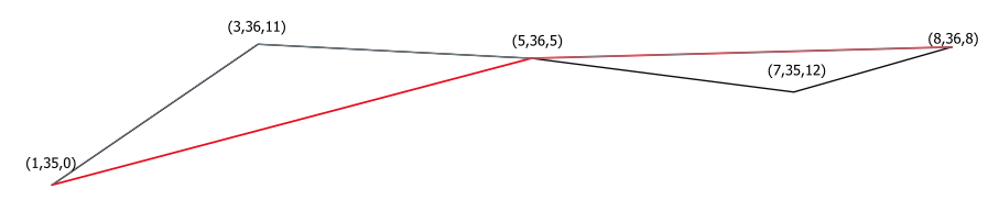
Fig. 24.134 The red line represents the black line with only vertices whose M value is <=10.
Allows
features in-place modification
of point, line and polygon features with M enabled
Warning
Depending on the input geometry attributes and the filters used, the geometries created by this algorithm may no longer be valid.
Parameters
Label |
Name |
Type |
Description |
|---|---|---|---|
Input layer |
|
[vector: geometry] |
Input vector layer to remove vertices from |
Minimum Optional |
|
[numeric: double] Default: Not set |
Minimum of M values allowed |
Maximum Optional |
|
[numeric: double] Default: Not set |
Maximum of M values allowed |
Filtered |
|
[same as input] Default: |
Specify the output vector layer. One of:
The file encoding can also be changed here. |
Outputs
Label |
Name |
Type |
Description |
|---|---|---|---|
Filtered |
|
[same as input] |
The output vector layer of features with only the filtered vertices. |
Python code
Algorithm ID: native:filterverticesbym
import processing
processing.run("algorithm_id", {parameter_dictionary})
The algorithm id is displayed when you hover over the algorithm in the Processing Toolbox. The parameter dictionary provides the parameter NAMEs and values. See Using processing algorithms from the console for details on how to run processing algorithms from the Python console.
24.1.26.33. Filter vertices by Z value
Filters away vertices based on their Z value, returning geometries with only vertex points that have a Z value greater than or equal to the specified minimum value and/or less than or equal to the maximum value.
If the minimum value is not specified then only the maximum value is tested, and similarly if the maximum value is not specified then only the minimum value is tested.
Fig. 24.135 The red line represents the black line with only vertices whose Z value is <=10.
Allows
features in-place modification
of point, line and polygon features with Z enabled
Warning
Depending on the input geometry attributes and the filters used, the geometries created by this algorithm may no longer be valid. You may need to run the Fix geometries algorithm to ensure their validity.
Parameters
Label |
Name |
Type |
Description |
|---|---|---|---|
Input layer |
|
[vector: geometry] |
Input vector layer to remove vertices from |
Minimum Optional |
|
[numeric: double] Default: Not set |
Minimum of Z values allowed |
Maximum Optional |
|
[numeric: double] Default: Not set |
Maximum of Z values allowed |
Filtered |
|
[same as input] Default: |
Specify the output vector layer. One of:
The file encoding can also be changed here. |
Outputs
Label |
Name |
Type |
Description |
|---|---|---|---|
Filtered |
|
[same as input] |
The output vector layer of features with only the filtered vertices. |
Python code
Algorithm ID: native:filterverticesbyz
import processing
processing.run("algorithm_id", {parameter_dictionary})
The algorithm id is displayed when you hover over the algorithm in the Processing Toolbox. The parameter dictionary provides the parameter NAMEs and values. See Using processing algorithms from the console for details on how to run processing algorithms from the Python console.
24.1.26.34. Fix geometries
Attempts to create a valid representation of a given invalid geometry without losing any of the input vertices. Already valid geometries are returned without further intervention. Always outputs multi-geometry layer.
Allows
features in-place modification
of point, line, and polygon features without M enabled
Warning
M values will be dropped from the output.
See also
Parameters
Label |
Name |
Type |
Description |
|---|---|---|---|
Input layer |
|
[vector: geometry] |
Input vector layer |
Repair method |
|
[enumeration] Default: 1 |
Method used to repair the geometries. One of:
|
Fixed geometries |
|
[same as input] Default: |
Specify the output vector layer. One of:
The file encoding can also be changed here. |
Outputs
Label |
Name |
Type |
Description |
|---|---|---|---|
Fixed geometries |
|
[same as input] |
The output vector layer with fixed geometries. |
Python code
Algorithm ID: native:fixgeometries
import processing
processing.run("algorithm_id", {parameter_dictionary})
The algorithm id is displayed when you hover over the algorithm in the Processing Toolbox. The parameter dictionary provides the parameter NAMEs and values. See Using processing algorithms from the console for details on how to run processing algorithms from the Python console.
24.1.26.35. Force polygons clockwise
Added in 4.0
Forces polygon geometries to respect the convention where the exterior ring is oriented in a clockwise direction and the interior rings in a counter-clockwise direction.
Allows
features in-place modification
of polygon features
Parameters
Label |
Name |
Type |
Description |
|---|---|---|---|
Input layer |
|
[vector: polygon] |
Input vector layer |
Reoriented |
|
[vector: polygon] Default: |
Specify the output vector layer. One of:
The file encoding can also be changed here. |
Outputs
Label |
Name |
Type |
Description |
|---|---|---|---|
Reoriented |
|
[vector: polygon] |
The output vector layer with reoriented geometries. |
Python code
Algorithm ID: native:forcecw
import processing
processing.run("algorithm_id", {parameter_dictionary})
The algorithm id is displayed when you hover over the algorithm in the Processing Toolbox. The parameter dictionary provides the parameter NAMEs and values. See Using processing algorithms from the console for details on how to run processing algorithms from the Python console.
24.1.26.36. Force polygons counter-clockwise
Added in 4.0
Forces polygon geometries to respect the convention where the exterior ring is oriented in a counter-clockwise direction and the interior rings in a clockwise direction.
Allows
features in-place modification
of polygon features
Parameters
Label |
Name |
Type |
Description |
|---|---|---|---|
Input layer |
|
[vector: polygon] |
Input vector layer |
Reoriented |
|
[vector: polygon] Default: |
Specify the output vector layer. One of:
The file encoding can also be changed here. |
Outputs
Label |
Name |
Type |
Description |
|---|---|---|---|
Reoriented |
|
[vector: polygon] |
The output vector layer with reoriented geometries. |
Python code
Algorithm ID: native:forceccw
import processing
processing.run("algorithm_id", {parameter_dictionary})
The algorithm id is displayed when you hover over the algorithm in the Processing Toolbox. The parameter dictionary provides the parameter NAMEs and values. See Using processing algorithms from the console for details on how to run processing algorithms from the Python console.
24.1.26.37. Force right-hand-rule
Forces polygon geometries to respect the Right-Hand-Rule, in which the area that is bounded by a polygon is to the right of the boundary. In particular, the exterior ring is oriented in a clockwise direction and any interior rings in a counter-clockwise direction.
Due to the inconsistency in the definition of the Right-Hand-Rule in some contexts, it is recommended to use the explicit Force polygons clockwise algorithm instead.
Allows
features in-place modification
of polygon features
Parameters
Label |
Name |
Type |
Description |
|---|---|---|---|
Input layer |
|
[vector: polygon] |
Input vector layer |
Reoriented |
|
[vector: polygon] Default: |
Specify the output vector layer. One of:
The file encoding can also be changed here. |
Outputs
Label |
Name |
Type |
Description |
|---|---|---|---|
Reoriented |
|
[vector: polygon] |
The output vector layer with reoriented geometries. |
Python code
Algorithm ID: native:forcerhr
import processing
processing.run("algorithm_id", {parameter_dictionary})
The algorithm id is displayed when you hover over the algorithm in the Processing Toolbox. The parameter dictionary provides the parameter NAMEs and values. See Using processing algorithms from the console for details on how to run processing algorithms from the Python console.
24.1.26.38. Geodesic line split at antimeridian
Splits a line into multiple geodesic segments, whenever the line crosses the antimeridian (±180 degrees longitude).
Splitting at the antimeridian helps the visual display of the lines in some projections. The returned geometry will always be a multi-part geometry.
Whenever line segments in the input geometry cross the antimeridian, they will be split into two segments, with the latitude of the breakpoint being determined using a geodesic line connecting the points either side of this segment. The current project ellipsoid setting will be used when calculating this breakpoint.
If the input geometry contains M or Z values, these will be linearly interpolated for the new vertices created at the antimeridian.
Note
This algorithm uses ellipsoid based measurements and respects the current ellipsoid settings.
Allows
features in-place modification
of line features
Parameters
Label |
Name |
Type |
Description |
|---|---|---|---|
Input layer |
|
[vector: line] |
Input line vector layer |
Split |
|
[vector: line] Default: |
Specify the output line vector layer. One of:
The file encoding can also be changed here. |
Outputs
Label |
Name |
Type |
Description |
|---|---|---|---|
Split |
|
[vector: line] |
The output line vector layer split at the antimeridian. |
Python code
Algorithm ID: native:antimeridiansplit
import processing
processing.run("algorithm_id", {parameter_dictionary})
The algorithm id is displayed when you hover over the algorithm in the Processing Toolbox. The parameter dictionary provides the parameter NAMEs and values. See Using processing algorithms from the console for details on how to run processing algorithms from the Python console.
24.1.26.39. Geometry by expression
Updates existing geometries (or creates new geometries) for input features by use of a QGIS expression.
This allows complex geometry modifications which can utilize all the flexibility of the QGIS expression engine to manipulate and create geometries for output features.
For help with QGIS expression functions, see the inbuilt help available in the expression builder.
Parameters
Label |
Name |
Type |
Description |
|---|---|---|---|
Input layer |
|
[vector: any] |
Input vector layer |
Output geometry type |
|
[enumeration] Default: 0 |
The output geometry strongly depends on the expression: for instance, if you create a buffer the geometry type has to be polygon. One of:
|
Output geometry has z values |
|
[boolean] Default: False |
Choose if the output geometry should include the Z dimension |
Output geometry has m values |
|
[boolean] Default: False |
Choose if the output geometry should include the M dimension |
Geometry expression |
|
[expression] Default: ‘$geometry’ |
Add the geometry expression you want to use. You can use the button to open the Expression Dialog. The dialog lists all the relevant expressions, together with their help and guide. |
Modified geometry |
|
[vector: geometry] Default: |
Specify the output vector layer. One of:
The file encoding can also be changed here. |
Outputs
Label |
Name |
Type |
Description |
|---|---|---|---|
Modified geometry |
|
[vector: geometry] |
The output vector layer |
Python code
Algorithm ID: native:geometrybyexpression
import processing
processing.run("algorithm_id", {parameter_dictionary})
The algorithm id is displayed when you hover over the algorithm in the Processing Toolbox. The parameter dictionary provides the parameter NAMEs and values. See Using processing algorithms from the console for details on how to run processing algorithms from the Python console.
24.1.26.40. Interpolate point on line
Creates a point geometry interpolated at a set distance along line or curve geometries.
Z and M values are linearly interpolated from existing values.
If a multipart geometry is encountered, only the first part is considered when calculating the substring.
If the specified distance is greater than the input feature’s length, the resultant feature will have a null geometry.
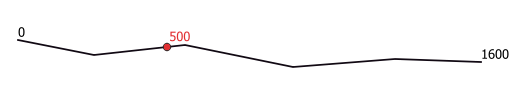
Fig. 24.136 Interpolated point at 500m of the beginning of the line
See also
Parameters
Label |
Name |
Type |
Description |
|---|---|---|---|
Input layer |
|
[vector: line, polygon] |
Input line or polygon vector layer |
Distance |
|
[numeric: double] Default: 0.0 |
Distance from the beginning of the line |
Interpolated points |
|
[vector: point] Default: |
Specify the output vector layer. One of:
The file encoding can also be changed here. |
Outputs
Label |
Name |
Type |
Description |
|---|---|---|---|
Interpolated points |
|
[vector: point] |
The output point vector layer with features at a set distance along the line or polygon boundary |
Python code
Algorithm ID: native:interpolatepoint
import processing
processing.run("algorithm_id", {parameter_dictionary})
The algorithm id is displayed when you hover over the algorithm in the Processing Toolbox. The parameter dictionary provides the parameter NAMEs and values. See Using processing algorithms from the console for details on how to run processing algorithms from the Python console.
24.1.26.41. Keep N biggest parts
Takes a layer with polygons or multipolygons and returns a new layer in which only the n largest polygons of each multipolygon feature are kept. If a feature has n or fewer parts, the feature will just be copied.
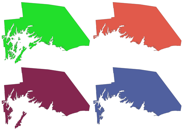
Fig. 24.137 Clockwise from top left: original multipart feature, one, two and three biggest parts kept
Parameters
Label |
Name |
Type |
Description |
|---|---|---|---|
Polygons |
|
[vector: polygon] |
Input polygon vector layer |
Parts to keep |
|
[numeric: integer] Default: 1 |
Number of parts to keep. If 1, only the biggest part of the feature will be kept. |
Parts |
|
[vector: polygon] Default: |
Specify the output polygon vector layer. One of:
The file encoding can also be changed here. |
Outputs
Label |
Name |
Type |
Description |
|---|---|---|---|
Parts |
|
[vector: polygon] |
The output polygon vector layer with the N biggest parts of each feature |
Python code
Algorithm ID: native:keepnbiggestparts
import processing
processing.run("algorithm_id", {parameter_dictionary})
The algorithm id is displayed when you hover over the algorithm in the Processing Toolbox. The parameter dictionary provides the parameter NAMEs and values. See Using processing algorithms from the console for details on how to run processing algorithms from the Python console.
24.1.26.42. Line substring
Returns the portion of a line (or curve) which falls between the specified start and end distances (measured from the beginning of the line).
Z and M values are linearly interpolated from existing values.
If a multipart geometry is encountered, only the first part is considered when calculating the substring.
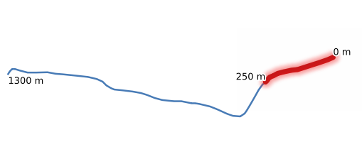
Fig. 24.138 Substring line with starting distance set at 0 meters and the ending distance at 250 meters.
Allows features in-place modification
of line features
See also
Parameters
Label |
Name |
Type |
Description |
|---|---|---|---|
Input layer |
|
[vector: line] |
Input line vector layer |
Start distance |
|
[numeric: double] Default: 0.0 |
Distance along the input line to the start point of the output feature |
End distance |
|
[numeric: double] Default: 1.0 |
Distance along the input line to the end point of the output feature |
Substring |
|
[vector: line] Default: |
Specify the output line vector layer. One of:
The file encoding can also be changed here. |
Outputs
Label |
Name |
Type |
Description |
|---|---|---|---|
Substring |
|
[vector: line] |
The output line vector layer. |
Python code
Algorithm ID: native:linesubstring
import processing
processing.run("algorithm_id", {parameter_dictionary})
The algorithm id is displayed when you hover over the algorithm in the Processing Toolbox. The parameter dictionary provides the parameter NAMEs and values. See Using processing algorithms from the console for details on how to run processing algorithms from the Python console.
24.1.26.43. Lines to polygons
Generates a polygon layer using as polygon rings the lines from an input line layer.
The attribute table of the output layer is the same as the one of the input layer.
Default menu:
See also
Parameters
Label |
Name |
Type |
Description |
|---|---|---|---|
Input layer |
|
[vector: line] |
Input line vector layer |
Polygons |
|
[vector: polygon] Default: |
Specify the output polygon vector layer. One of:
The file encoding can also be changed here. |
Outputs
Label |
Name |
Type |
Description |
|---|---|---|---|
Polygons |
|
[vector: polygon] |
The output polygon vector layer. |
Python code
Algorithm ID: qgis:linestopolygons
import processing
processing.run("algorithm_id", {parameter_dictionary})
The algorithm id is displayed when you hover over the algorithm in the Processing Toolbox. The parameter dictionary provides the parameter NAMEs and values. See Using processing algorithms from the console for details on how to run processing algorithms from the Python console.
24.1.26.44. Merge lines
Joins all connected parts of MultiLineString geometries into single LineString geometries.
If any parts of the input MultiLineString geometries are not connected, the resultant geometry will be a MultiLineString containing any lines which could be merged and any non-connected line parts.
Allows
features in-place modification
of line features
Parameters
Label |
Name |
Type |
Description |
|---|---|---|---|
Input layer |
|
[vector: line] |
Input line vector layer |
Merged |
|
[vector: line] Default: |
Specify the output line vector layer. One of:
The file encoding can also be changed here. |
Outputs
Label |
Name |
Type |
Description |
|---|---|---|---|
Merged |
|
[vector: line] |
The output (merged) line vector layer. |
Python code
Algorithm ID: native:mergelines
import processing
processing.run("algorithm_id", {parameter_dictionary})
The algorithm id is displayed when you hover over the algorithm in the Processing Toolbox. The parameter dictionary provides the parameter NAMEs and values. See Using processing algorithms from the console for details on how to run processing algorithms from the Python console.
24.1.26.45. Minimum bounding geometry
Creates geometries which enclose the features from an input layer. The features can be grouped by a field. The output layer will then contain one feature per group value with a geometry (MBB) that covers the geometries of the features with matching value.
The following enclosing geometry types are supported:
bounding box (envelope)
oriented rectangle
circle
convex hull
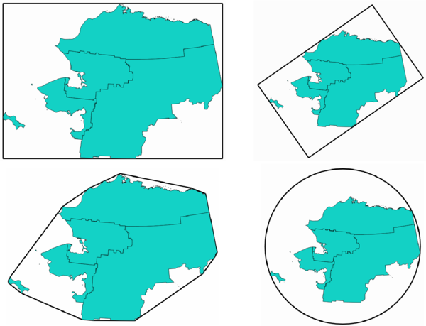
Fig. 24.139 Clockwise from top left: envelope, oriented rectangle, circle, convex hull
See also
Parameters
Label |
Name |
Type |
Description |
|---|---|---|---|
Input layer |
|
[vector: geometry] |
Input vector layer |
Field Optional |
|
[tablefield: any] |
Features can be grouped by a field. If set, this causes the output layer to contain one feature per grouped value with a minimal geometry covering only the features with matching values. |
Geometry type |
|
[enumeration] Default: 0 |
Enclosing geometry types. One of:
|
Bounding geometry |
|
[vector: polygon] Default: |
Specify the output polygon vector layer. One of:
The file encoding can also be changed here. |
Outputs
Label |
Name |
Type |
Description |
|---|---|---|---|
Bounding geometry |
|
[vector: polygon] |
The output (bounding) polygon vector layer.
It has the fields from the input layer
and, depending on the selected parameter
|
Python code
Algorithm ID: native:minimumboundinggeometry
import processing
processing.run("algorithm_id", {parameter_dictionary})
The algorithm id is displayed when you hover over the algorithm in the Processing Toolbox. The parameter dictionary provides the parameter NAMEs and values. See Using processing algorithms from the console for details on how to run processing algorithms from the Python console.
24.1.26.46. Minimum enclosing circles
Calculates the minimum enclosing circles of the features in the input layer.
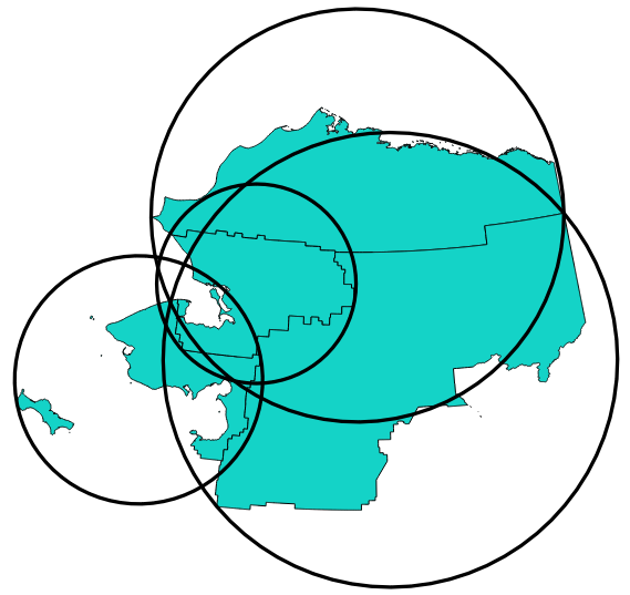
Fig. 24.140 Enclosing circles for each feature
Allows
features in-place modification
of polygon features
See also
Parameters
Label |
Name |
Type |
Description |
|---|---|---|---|
Input layer |
|
[vector: geometry] |
Input vector layer |
Number of segments in circles |
|
[numeric: integer] Default: 72 |
The number of segments used to approximate a circle. Minimum 8, maximum 100000. |
Minimum enclosing circles |
|
[vector: polygon] Default: |
Specify the output polygon vector layer. One of:
The file encoding can also be changed here. |
Outputs
Label |
Name |
Type |
Description |
|---|---|---|---|
Minimum enclosing circles |
|
[vector: polygon] |
The output polygon vector layer.
Other than the input attributes, the output layer also contains the following fields:
|
Python code
Algorithm ID: native:minimumenclosingcircle
import processing
processing.run("algorithm_id", {parameter_dictionary})
The algorithm id is displayed when you hover over the algorithm in the Processing Toolbox. The parameter dictionary provides the parameter NAMEs and values. See Using processing algorithms from the console for details on how to run processing algorithms from the Python console.
24.1.26.47. Multi-ring buffer (constant distance)
Computes multi-ring (donut) buffer for the features of the input layer, using a fixed or dynamic distance and number of rings.
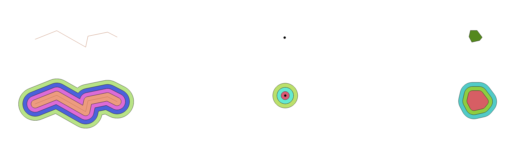
Fig. 24.141 Multi-ring buffer for a line, point and polygon layer
Allows
features in-place modification
of polygon features
Warning
This algorithm drops existing primary keys or FID values and regenerates them in output layers.
Parameters
Label |
Name |
Type |
Description |
|---|---|---|---|
Input layer |
|
[vector: geometry] |
Input vector layer |
Number of rings |
|
[numeric: integer] Default: 1 |
The number of rings. It can be a unique value (same number of rings for all the features) or it can be taken from features data (the number of rings depends on feature values). |
Distance between rings |
|
[numeric: double] Default: 1.0 |
Distance between the rings. It can be a unique value (same distance for all the features) or it can be taken from features data (the distance depends on feature values). |
Multi-ring buffer (constant distance) |
|
[vector: polygon] Default: |
Specify the output polygon vector layer. One of:
The file encoding can also be changed here. |
Outputs
Label |
Name |
Type |
Description |
|---|---|---|---|
Multi-ring buffer (constant distance) |
|
[vector: polygon] |
The output polygon vector layer.
Other than the input attributes, the output layer also contains the following fields:
|
Python code
Algorithm ID: native:multiringconstantbuffer
import processing
processing.run("algorithm_id", {parameter_dictionary})
The algorithm id is displayed when you hover over the algorithm in the Processing Toolbox. The parameter dictionary provides the parameter NAMEs and values. See Using processing algorithms from the console for details on how to run processing algorithms from the Python console.
24.1.26.48. Multipart to singleparts
Splits multipart features in the input layer into singlepart features.
The attributes of the output layer are the same as the original ones but divided into single features.
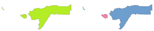
Fig. 24.142 Left the multipart source layer and right the single part output result
Allows
features in-place modification
of point, line, and polygon features
Default menu:
Warning
This algorithm drops existing primary keys or FID values and regenerates them in output layers.
See also
Parameters
Label |
Name |
Type |
Description |
|---|---|---|---|
Input layer |
|
[vector: geometry] |
Input vector layer |
Single parts |
|
[same as input] Default: |
Specify the output polygon vector layer. One of:
The file encoding can also be changed here. |
Outputs
Label |
Name |
Type |
Description |
|---|---|---|---|
Single parts |
|
[same as input] |
The output vector layer. |
Python code
Algorithm ID: native:multiparttosingleparts
import processing
processing.run("algorithm_id", {parameter_dictionary})
The algorithm id is displayed when you hover over the algorithm in the Processing Toolbox. The parameter dictionary provides the parameter NAMEs and values. See Using processing algorithms from the console for details on how to run processing algorithms from the Python console.
24.1.26.49. Offset lines
Offsets lines by a specified distance. Positive distances will offset lines to the left, and negative distances will offset them to the right.
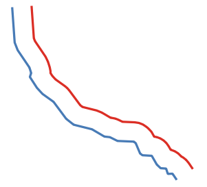
Fig. 24.143 In blue the source layer, in red the offset one
Allows
features in-place modification
of line features
See also
Parameters
Label |
Name |
Type |
Description |
|---|---|---|---|
Input layer |
|
[vector: line] |
Input line vector layer |
Distance |
|
[numeric: double] Default: 10.0 |
Offset distance. You can use the Data Defined button on the right to choose a field from which the radius will be calculated. This way you can have different radius for each feature (see Variable distance buffer). |
Segments |
|
[numeric: integer] Default: 8 |
Controls the number of line segments to use to approximate a quarter circle when creating rounded offsets. |
Join style |
|
[enumeration] Default: 0 |
Specifies whether round, miter or beveled joins should be used when offsetting corners in a line. Options are:
Fig. 24.144 Round, miter, and bevel join styles |
Miter limit |
|
[numeric: double] Default: 2.0 |
Sets the maximum distance from the offset geometry to use when creating a mitered join as a factor of the offset distance (only applicable for miter join styles). Minimum: 1.0
Fig. 24.145 A 10m buffer with a limit of 2 and a 10m buffer with a limit of 1 |
Offset |
|
[vector: line] Default: |
Specify the output (offset) layer. One of:
The file encoding can also be changed here. |
Outputs
Label |
Name |
Type |
Description |
|---|---|---|---|
Offset |
|
[vector: line] |
Output (offset) line layer |
Python code
Algorithm ID: native:offsetline
import processing
processing.run("algorithm_id", {parameter_dictionary})
The algorithm id is displayed when you hover over the algorithm in the Processing Toolbox. The parameter dictionary provides the parameter NAMEs and values. See Using processing algorithms from the console for details on how to run processing algorithms from the Python console.
24.1.26.50. Oriented minimum bounding box
Calculates the minimum area rotated rectangle for each feature in the input layer.
Note
For singlepart point features, the output corresponds to the bounding box of the geometry.
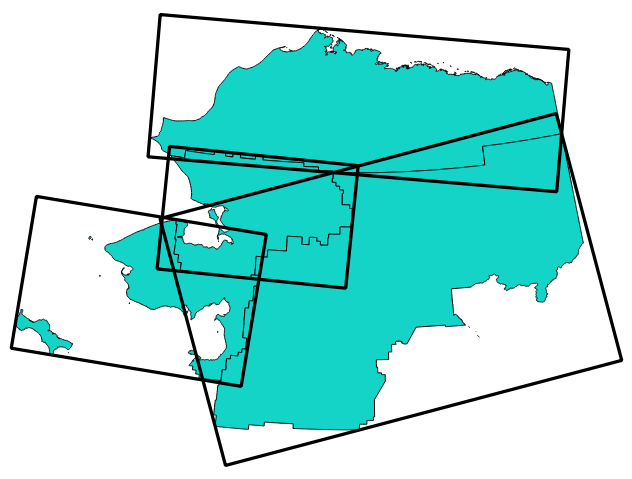
Fig. 24.146 Oriented minimum bounding box
Allows
features in-place modification
of polygon features
See also
Parameters
Label |
Name |
Type |
Description |
|---|---|---|---|
Input layer |
|
[vector: geometry] |
Input vector layer |
Bounding boxes |
|
[vector: polygon] Default: |
Specify the output polygon vector layer. One of:
The file encoding can also be changed here. |
Outputs
Label |
Name |
Type |
Description |
|---|---|---|---|
Bounding boxes |
|
[vector: polygon] |
The output polygon vector layer.
Other than the input attributes, the output layer also contains the following fields:
|
Python code
Algorithm ID: native:orientedminimumboundingbox
import processing
processing.run("algorithm_id", {parameter_dictionary})
The algorithm id is displayed when you hover over the algorithm in the Processing Toolbox. The parameter dictionary provides the parameter NAMEs and values. See Using processing algorithms from the console for details on how to run processing algorithms from the Python console.
24.1.26.51. Orthogonalize
Attempts to orthogonalize the geometries of the input line or polygon layer. This process shifts the vertices in the geometries to try to make every angle in the geometry either a right angle or a straight line.
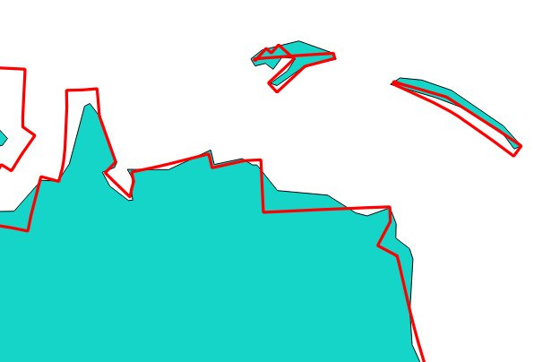
Fig. 24.147 In blue the source layer and in the red orthogonalized result
Allows
features in-place modification
of line and polygon features
Parameters
Label |
Name |
Type |
Description |
|---|---|---|---|
Input layer |
|
[vector: line, polygon] |
Input line or polygon vector layer |
Maximum angle tolerance (degrees) |
|
[numeric: double] Default: 15.0 |
Specify the maximum deviation from a right angle or straight line a vertex can have for it to be adjusted. Smaller tolerances mean that only vertices which are already closer to right angles will be adjusted, and larger tolerances mean that vertices which deviate further from right angles will also be adjusted. |
Maximum algorithm iterations |
|
[numeric: integer] Default: 1000 |
Setting a larger number for the maximum number of iterations will result in a more orthogonal geometry at the cost of extra processing time. |
Orthogonalized |
|
[same as input] Default: |
Specify the output polygon vector layer. One of:
The file encoding can also be changed here. |
Outputs
Label |
Name |
Type |
Description |
|---|---|---|---|
Orthogonalized |
|
[same as input] |
The output polygon vector layer with adjusted angles. |
Python code
Algorithm ID: native:orthogonalize
import processing
processing.run("algorithm_id", {parameter_dictionary})
The algorithm id is displayed when you hover over the algorithm in the Processing Toolbox. The parameter dictionary provides the parameter NAMEs and values. See Using processing algorithms from the console for details on how to run processing algorithms from the Python console.
24.1.26.52. Point on Surface
For each feature of the input layer, returns a point that is guaranteed to lie on the surface of the feature geometry.
Allows
features in-place modification
of point features
Warning
This algorithm may drop existing primary keys or FID values and regenerate them in output layers, depending on the input parameters.
See also
Parameters
Label |
Name |
Type |
Description |
|---|---|---|---|
Input layer |
|
[vector: geometry] |
Input vector layer |
Create point on surface for each part |
|
[boolean] |
If checked, a point will be created for each part of the geometry. |
Point |
|
[vector: point] Default: |
Specify the output point vector layer. One of:
The file encoding can also be changed here. |
Outputs
Label |
Name |
Type |
Description |
|---|---|---|---|
Point |
|
[vector: point] |
The output point vector layer. |
Python code
Algorithm ID: native:pointonsurface
import processing
processing.run("algorithm_id", {parameter_dictionary})
The algorithm id is displayed when you hover over the algorithm in the Processing Toolbox. The parameter dictionary provides the parameter NAMEs and values. See Using processing algorithms from the console for details on how to run processing algorithms from the Python console.
24.1.26.53. Points along geometry
Creates points at regular intervals along line or polygon geometries. Created points will have new attributes added for the distance along the geometry and the angle of the line at the point.
An optional start and end offset can be specified, which controls how far from the start and end of the geometry the points should be created.
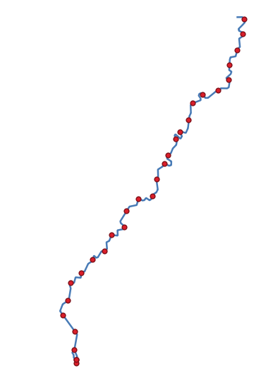
Fig. 24.148 Points created along the source line layer
Warning
This algorithm drops existing primary keys or FID values and regenerates them in output layers.
See also
Parameters
Label |
Name |
Type |
Description |
|---|---|---|---|
Input layer |
|
[vector: line, polygon] |
Input line or polygon vector layer |
Distance |
|
[numeric: double] Default: 1.0 |
Distance between two consecutive points along the line |
Start offset |
|
[numeric: double] Default: 0.0 |
Distance from the beginning of the input line, representing the position of the first point. |
End offset |
|
[numeric: double] Default: 0.0 |
Distance from the end of the input line, representing the position beyond which no point feature should be created. |
Interpolated points |
|
[vector: point] Default: |
Specify the output vector layer. One of:
The file encoding can also be changed here. |
Outputs
Label |
Name |
Type |
Description |
|---|---|---|---|
Interpolated points |
|
[vector: point] |
Point vector layer with features placed along lines or polygon
boundaries of the input layer.
Other than the input attributes on every related point, the output layer
also contains the following fields:
|
Python code
Algorithm ID: native:pointsalonglines
import processing
processing.run("algorithm_id", {parameter_dictionary})
The algorithm id is displayed when you hover over the algorithm in the Processing Toolbox. The parameter dictionary provides the parameter NAMEs and values. See Using processing algorithms from the console for details on how to run processing algorithms from the Python console.
24.1.26.54. Points displacement
Given a distance of proximity, identifies nearby point features and radially distributes them over a circle whose center represents their barycenter. A convenient tool to scatter overlaid features.
Parameters
Label |
Name |
Type |
Description |
|---|---|---|---|
Input layer |
|
[vector: point] |
Input point vector layer |
Minimum distance to other points |
|
[numeric: double] Default: 1.0 |
Distance below which point features are considered close. Close features are distributed altogether. |
Displacement distance |
|
[numeric: double] Default: 1.0 |
Radius of the circle on which close features are placed |
Horizontal distribution for two point case |
|
[boolean] Default: False |
When only two points are identified as close, aligns them horizontally on the circle instead of vertically. |
Displaced |
|
[vector: point] Default: |
Specify the output vector layer. One of:
The file encoding can also be changed here. |
Outputs
Label |
Name |
Type |
Description |
|---|---|---|---|
Displaced |
|
[vector: point] |
Output point vector layer |
Python code
Algorithm ID: qgis:pointsdisplacement
import processing
processing.run("algorithm_id", {parameter_dictionary})
The algorithm id is displayed when you hover over the algorithm in the Processing Toolbox. The parameter dictionary provides the parameter NAMEs and values. See Using processing algorithms from the console for details on how to run processing algorithms from the Python console.
24.1.26.55. Pole of inaccessibility
Calculates the pole of inaccessibility for a polygon layer, which is the most distant internal point from the boundary of the surface.
This algorithm uses the ‘polylabel’ algorithm (Vladimir Agafonkin, 2016), which is an iterative approach guaranteed to find the true pole of inaccessibility within a specified tolerance. A more precise tolerance (lower value) requires more iterations and will take longer to calculate.
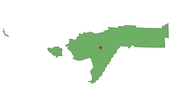
Fig. 24.149 Pole of inaccessibility
Parameters
Label |
Name |
Type |
Description |
|---|---|---|---|
Input layer |
|
[vector: polygon] |
Input vector layer |
Tolerance |
|
[numeric: double] Default: 1.0 |
Set the tolerance for the calculation |
Point |
|
[vector: point] Default: |
Specify the output polygon vector layer. One of:
The file encoding can also be changed here. |
Outputs
Label |
Name |
Type |
Description |
|---|---|---|---|
Point |
|
[vector: point] |
The output point vector layer.
It will contain a new attribute with the distance |
Python code
Algorithm ID: native:poleofinaccessibility
import processing
processing.run("algorithm_id", {parameter_dictionary})
The algorithm id is displayed when you hover over the algorithm in the Processing Toolbox. The parameter dictionary provides the parameter NAMEs and values. See Using processing algorithms from the console for details on how to run processing algorithms from the Python console.
24.1.26.56. Polygonize
Creates a polygon layer whose features boundaries are generated from a line layer of closed features.
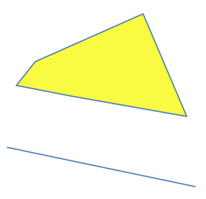
Fig. 24.150 The yellow polygons generated from the closed lines
Note
The line layer must have closed shapes in order to be transformed into a polygon.
Parameters
Label |
Name |
Type |
Description |
|---|---|---|---|
Input layer |
|
[vector: line] |
Input line vector layer |
Keep fields from the input layer |
|
[boolean] Default: False |
Check to keep the fields (only the table structure, not the values) of the input layer |
Polygons from lines |
|
[vector: polygon] Default: |
Specify the output polygon vector layer. One of:
The file encoding can also be changed here. |
Outputs
Label |
Name |
Type |
Description |
|---|---|---|---|
Polygons from lines |
|
[vector: polygon] |
The output polygon vector layer from lines |
Python code
Algorithm ID: native:polygonize
import processing
processing.run("algorithm_id", {parameter_dictionary})
The algorithm id is displayed when you hover over the algorithm in the Processing Toolbox. The parameter dictionary provides the parameter NAMEs and values. See Using processing algorithms from the console for details on how to run processing algorithms from the Python console.
24.1.26.57. Polygons to lines
Takes a polygon layer and creates a line layer, with lines representing the boundaries of the polygons in the input layer.
The attribute table of the output layer is the same as the one of the input layer.
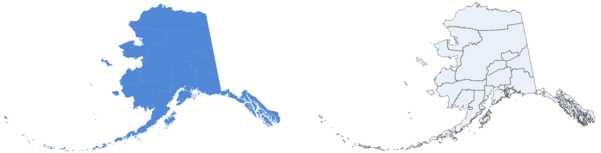
Fig. 24.151 Black lines as the result of the algorithm
Default menu:
See also
Parameters
Label |
Name |
Type |
Description |
|---|---|---|---|
Input layer |
|
[vector: polygon] |
Input polygon vector layer |
Lines |
|
[vector: line] Default: |
Specify the output line vector layer. One of:
The file encoding can also be changed here. |
Outputs
Label |
Name |
Type |
Description |
|---|---|---|---|
Lines |
|
[vector: line] |
The output line vector layer from polygons |
Python code
Algorithm ID: native:polygonstolines
import processing
processing.run("algorithm_id", {parameter_dictionary})
The algorithm id is displayed when you hover over the algorithm in the Processing Toolbox. The parameter dictionary provides the parameter NAMEs and values. See Using processing algorithms from the console for details on how to run processing algorithms from the Python console.
24.1.26.58. Project points (Cartesian)
Projects point geometries by a specified distance and bearing (azimuth).
Allows
features in-place modification
of point features
Parameters
Label |
Name |
Type |
Description |
|---|---|---|---|
Input layer |
|
[vector: point] |
Input point vector layer |
Bearing (degrees from North) |
|
[numeric: double] Default: 0.0 |
Clockwise angle starting from North, in degree (°) unit |
Distance |
|
[numeric: double] Default: 1.0 |
Distance to offset geometries, in layer units |
Projected |
|
[vector: point] Default: |
Specify the output point vector layer. One of:
The file encoding can also be changed here. |
Outputs
Label |
Name |
Type |
Description |
|---|---|---|---|
Projected |
|
[vector: point] |
The output (projected) point vector layer |
Python code
Algorithm ID: native:projectpointcartesian
import processing
processing.run("algorithm_id", {parameter_dictionary})
The algorithm id is displayed when you hover over the algorithm in the Processing Toolbox. The parameter dictionary provides the parameter NAMEs and values. See Using processing algorithms from the console for details on how to run processing algorithms from the Python console.
24.1.26.59. Promote to multipart
Takes a vector layer with singlepart geometries and generates a new one in which all geometries are multipart.
Input features which are already multipart features will remain unchanged.
This algorithm can be used to force geometries to multipart types in order to be compatible with data providers that require multipart features.
Allows
features in-place modification
of point, line, and polygon features
Parameters
Label |
Name |
Type |
Description |
|---|---|---|---|
Input layer |
|
[vector: geometry] |
Input vector layer |
Multiparts |
|
[same as input] Default: |
Specify the output multipart vector layer. One of:
The file encoding can also be changed here. |
Outputs
Label |
Name |
Type |
Description |
|---|---|---|---|
Multiparts |
|
[same as input] |
The output multipart vector layer |
Python code
Algorithm ID: native:promotetomulti
import processing
processing.run("algorithm_id", {parameter_dictionary})
The algorithm id is displayed when you hover over the algorithm in the Processing Toolbox. The parameter dictionary provides the parameter NAMEs and values. See Using processing algorithms from the console for details on how to run processing algorithms from the Python console.
24.1.26.60. Rectangles, ovals, diamonds
Creates a buffer area with a rectangle, oval or diamond shape for each feature of the input point layer.
The shape parameters can be fixed for all features or dynamic using a field or an expression.
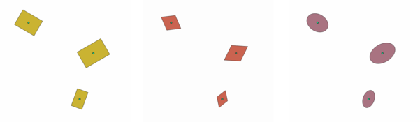
Fig. 24.152 Different buffer shapes with dynamic parameters
Parameters
Label |
Name |
Type |
Description |
|---|---|---|---|
Input layer |
|
[vector: point] |
Input point vector layer |
Buffer shape |
|
[enumeration] |
The shape to use. One of:
|
Width |
|
[numeric: double] Default: 1.0 |
Width of the buffer shape |
Height |
|
[numeric: double] Default: 1.0 |
Height of the buffer shape |
Rotation Optional |
|
[numeric: double] Default: 0.0 |
Rotation of the buffer shape |
Number of segments |
|
[numeric: integer] Default: 36 |
Number of segments for a full circle (Ovals shape) |
Output |
|
[vector: polygon] Default: |
Specify the output vector layer. One of:
The file encoding can also be changed here. |
Outputs
Label |
Name |
Type |
Description |
|---|---|---|---|
Output |
|
[vector: polygon] |
The output vector layer (with the buffer shapes) |
Python code
Algorithm ID: native:rectanglesovalsdiamonds
import processing
processing.run("algorithm_id", {parameter_dictionary})
The algorithm id is displayed when you hover over the algorithm in the Processing Toolbox. The parameter dictionary provides the parameter NAMEs and values. See Using processing algorithms from the console for details on how to run processing algorithms from the Python console.
24.1.26.61. Remove duplicate vertices
Removes duplicate vertices from features, wherever removing the vertices does not result in a degenerate geometry.
The tolerance parameter specifies the tolerance for coordinates when determining whether vertices are identical.
By default, Z values are not considered when detecting duplicate vertices. E.g. two vertices with the same X and Y coordinate but different Z values will still be considered duplicate and one will be removed. If the Use Z Value parameter is true, then the Z values are also tested and vertices with the same X and Y but different Z will be maintained.
Allows features in-place modification
of point, line, and polygon features
Note
Duplicate vertices are not tested between different parts of a multipart geometry, e.g. a multipoint geometry with overlapping points will not be changed by this method.
See also
Extract vertices, Extract specific vertices, Delete duplicate geometries, Delete duplicated vertices
Parameters
Label |
Name |
Type |
Description |
|---|---|---|---|
Input layer |
|
[vector: geometry] |
Input vector layer |
Tolerance |
|
[numeric: double] Default: 0.000001 |
Vertices closer than the specified distance are considered duplicates |
Use Z value |
|
[boolean] Default: False |
If the Use Z Value parameter is true, then the Z values are also tested and vertices with the same X and Y but different Z will be maintained. |
Cleaned |
|
[same as input] Default: |
Specify the output vector layer. One of:
The file encoding can also be changed here. |
Outputs
Label |
Name |
Type |
Description |
|---|---|---|---|
Cleaned |
|
[same as input] |
The output vector layer (without duplicate vertices) |
Python code
Algorithm ID: native:removeduplicatevertices
import processing
processing.run("algorithm_id", {parameter_dictionary})
The algorithm id is displayed when you hover over the algorithm in the Processing Toolbox. The parameter dictionary provides the parameter NAMEs and values. See Using processing algorithms from the console for details on how to run processing algorithms from the Python console.
24.1.26.62. Remove null geometries
Removes any features which do not have a geometry from a vector layer. All other features will be copied unchanged.
The features with null geometries can be saved to a separate layer.
If Also remove empty geometries is checked, the algorithm removes features whose geometries have no coordinates, i.e., geometries that are empty. In that case, also the null output will reflect this option, containing both null and empty geometries.
See also
Parameters
Label |
Name |
Type |
Description |
|---|---|---|---|
Input layer |
|
[vector: geometry] |
Input vector layer (with non-NULL geometries) |
Also remove empty geometries |
|
[boolean] |
|
Non null geometries |
Optional |
[same as input] Default: |
Specify the output vector layer for the non-NULL (and non-empty) geometries. One of:
The file encoding can also be changed here. |
Null geometries Optional |
|
[same as input] Default: |
Specify the output vector layer for the NULL (and empty) geometries. One of:
The file encoding can also be changed here. |
Outputs
Label |
Name |
Type |
Description |
|---|---|---|---|
Null geometries |
|
[same as input] |
Output vector layer (for NULL and, if chosen, empty geometries) |
Non null geometries |
|
[same as input] |
The output vector layer (without NULL and, if chosen, empty geometries) |
Python code
Algorithm ID: native:removenullgeometries
import processing
processing.run("algorithm_id", {parameter_dictionary})
The algorithm id is displayed when you hover over the algorithm in the Processing Toolbox. The parameter dictionary provides the parameter NAMEs and values. See Using processing algorithms from the console for details on how to run processing algorithms from the Python console.
24.1.26.63. Remove parts by area
Added in 4.0
Takes a polygon layer and removes polygons which are smaller than a specified area.
If the input geometry is a multipart geometry, then the parts will be filtered by their individual areas. If no parts match the required minimum area, then the feature will be skipped and omitted from the output layer.
If the input geometry is a singlepart geometry, then the feature will be skipped if the geometry’s area is below the required size and omitted from the output layer.
The area will be calculated using Cartesian calculations in the source layer’s coordinate reference system.
Attributes are not modified.
Allows features in-place modification
of line features
Parameters
Label |
Name |
Type |
Description |
|---|---|---|---|
Input layer |
|
[vector: polygon] |
Input vector layer whose features are to be filtered by area. |
Remove parts with area less than |
|
[numeric: double] Default: 0.0 |
Minimum area of the polygons to keep, using cartesian calculations in the layer’s CRS. |
Cleaned |
|
[vector: polygon] Default: |
Specify the polygon output vector layer. One of:
The file encoding can also be changed here. |
Outputs
Label |
Name |
Type |
Description |
|---|---|---|---|
Cleaned |
|
[vector: polygon] |
The output polygon vector layer with features whose individual parts have a surface greater than the given area. |
Python code
Algorithm ID: native:removepartsbyarea
import processing
processing.run("algorithm_id", {parameter_dictionary})
The algorithm id is displayed when you hover over the algorithm in the Processing Toolbox. The parameter dictionary provides the parameter NAMEs and values. See Using processing algorithms from the console for details on how to run processing algorithms from the Python console.
24.1.26.64. Remove parts by length
Added in 4.0
Takes a line layer and removes lines which are shorter than a specified length.
If the input geometry is a multipart geometry, then the parts will be filtered by their individual lengths. If no parts match the required minimum length, then the feature will be skipped and omitted from the output layer.
If the input geometry is a singlepart geometry, then the feature will be skipped if the geometry’s length is below the required size and omitted from the output layer.
The length will be calculated using Cartesian calculations in the source layer’s coordinate reference system.
Attributes are not modified.
Allows features in-place modification
of line features
Parameters
Label |
Name |
Type |
Description |
|---|---|---|---|
Input layer |
|
[vector: line] |
Input vector layer whose features are to be filtered by length. |
Remove parts with lengths less than |
|
[numeric: double] Default: 0.0 |
Minimum length of the lines to keep, using cartesian calculations in the layer’s CRS. |
Cleaned |
|
[vector: line] Default: |
Specify the line output vector layer. One of:
The file encoding can also be changed here. |
Outputs
Label |
Name |
Type |
Description |
|---|---|---|---|
Cleaned |
|
[vector: line] |
The output line vector layer with features whose individual parts are longer than the given value. |
Python code
Algorithm ID: native:removepartsbylength
import processing
processing.run("algorithm_id", {parameter_dictionary})
The algorithm id is displayed when you hover over the algorithm in the Processing Toolbox. The parameter dictionary provides the parameter NAMEs and values. See Using processing algorithms from the console for details on how to run processing algorithms from the Python console.
24.1.26.65. Reverse line direction
Inverts the direction of a line layer.
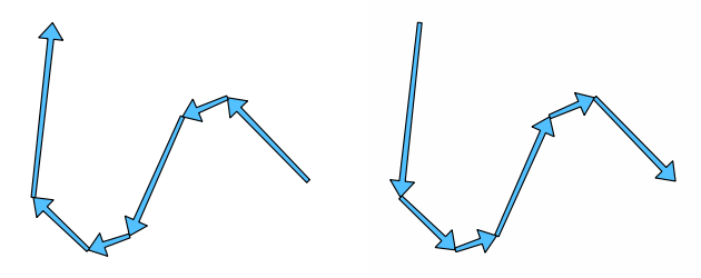
Fig. 24.153 Before and after the direction inversion
Allows features in-place modification
of line features
Parameters
Label |
Name |
Type |
Description |
|---|---|---|---|
Input layer |
|
[vector: line] |
Input line vector layer |
Reversed |
|
[vector: line] Default: |
Specify the output line vector layer. One of:
The file encoding can also be changed here. |
Outputs
Label |
Name |
Type |
Description |
|---|---|---|---|
Reversed |
|
[vector: line] |
The output line vector layer (with reversed lines) |
Python code
Algorithm ID: native:reverselinedirection
import processing
processing.run("algorithm_id", {parameter_dictionary})
The algorithm id is displayed when you hover over the algorithm in the Processing Toolbox. The parameter dictionary provides the parameter NAMEs and values. See Using processing algorithms from the console for details on how to run processing algorithms from the Python console.
24.1.26.66. Rotate
Rotates feature geometries by the specified angle clockwise. The rotation occurs around each feature’s centroid, or optionally around a unique preset point.
Allows
features in-place modification
of point, line, and polygon features
See also
Parameters
Label |
Name |
Type |
Description |
|---|---|---|---|
Input layer |
|
[vector: geometry] |
Input vector layer |
Rotation (degrees clockwise) |
|
[numeric: double] Default: 0.0 |
Angle of the rotation in degrees |
Rotation anchor point (x, y) Optional |
|
[coordinates] Default: Not set |
X,Y coordinates of the point to rotate the features around. If not set the rotation occurs around each feature’s centroid. |
Rotated |
|
[same as input] Default: |
Specify the output vector layer (with rotated geometries). One of:
The file encoding can also be changed here. |
Outputs
Label |
Name |
Type |
Description |
|---|---|---|---|
Rotated |
|
[same as input] |
The output vector layer with rotated geometries |
Python code
Algorithm ID: native:rotatefeatures
import processing
processing.run("algorithm_id", {parameter_dictionary})
The algorithm id is displayed when you hover over the algorithm in the Processing Toolbox. The parameter dictionary provides the parameter NAMEs and values. See Using processing algorithms from the console for details on how to run processing algorithms from the Python console.
24.1.26.67. Roundness
Calculates the roundness of each feature and stores it as a new field roundness. The input vector layer must contain polygons.
The roundness of a polygon is defined as 4π × polygon area / perimeter². The roundness value varies between 0 and 1. A perfect circle has a roundness of 1, while a completely flat polygon has a roundness of 0.
Note
The algorithm returns NULL for multipart polygon features.
Allows
features in-place modification
of polygon features
Parameters
Label |
Name |
Type |
Description |
|---|---|---|---|
Input layer |
|
[vector: polygon] |
Input vector layer |
Roundness |
|
[vector: polygon] Default: |
Specify the output vector layer (with roundness field). One of:
The file encoding can also be changed here. |
Outputs
Label |
Name |
Type |
Description |
|---|---|---|---|
Roundness |
|
[same as input] |
The output vector layer with |
Python code
Algorithm ID: native:roundness
import processing
processing.run("algorithm_id", {parameter_dictionary})
The algorithm id is displayed when you hover over the algorithm in the Processing Toolbox. The parameter dictionary provides the parameter NAMEs and values. See Using processing algorithms from the console for details on how to run processing algorithms from the Python console.
24.1.26.68. Segmentize by maximum angle
Segmentizes a geometry by converting curved sections to linear sections.
The segmentization is performed by specifying the maximum allowed radius angle between vertices on the straightened geometry (e.g the angle of the arc created from the original arc center to consecutive output vertices on the linearized geometry). Non-curved geometries will be retained without change.
See also
Parameters
Label |
Name |
Type |
Description |
|---|---|---|---|
Input layer |
|
[vector: line, polygon] |
Input line or polygon vector layer |
Maximum angle between vertices (degrees) |
|
[numeric: double] Default: 5.0 |
Maximum allowed radius angle between vertices on the straightened geometry |
Segmentized |
|
[same as input] Default: |
Specify the output vector layer (with segmentized geometries). One of:
The file encoding can also be changed here. |
Outputs
Label |
Name |
Type |
Description |
|---|---|---|---|
Segmentized |
|
[same as input] |
The output vector layer with segmentized geometries |
Python code
Algorithm ID: native:segmentizebymaxangle
import processing
processing.run("algorithm_id", {parameter_dictionary})
The algorithm id is displayed when you hover over the algorithm in the Processing Toolbox. The parameter dictionary provides the parameter NAMEs and values. See Using processing algorithms from the console for details on how to run processing algorithms from the Python console.
24.1.26.69. Segmentize by maximum distance
Segmentizes a geometry by converting curved sections to linear sections.
The segmentization is performed by specifying the maximum allowed offset distance between the original curve and the segmentized representation. Non-curved geometries will be retained without change.
See also
Parameters
Label |
Name |
Type |
Description |
|---|---|---|---|
Input layer |
|
[vector: line, polygon] |
Input line or polygon vector layer |
Maximum offset distance |
|
[numeric: double] Default: 1.0 |
Maximum allowed offset distance between the original curve and the segmentized representation, in the layer units. |
Segmentized |
|
[same as input] Default: |
Specify the output vector layer (with segmentized geometries). One of:
The file encoding can also be changed here. |
Outputs
Label |
Name |
Type |
Description |
|---|---|---|---|
Segmentized |
|
[same as input] |
The output vector layer with segmentized geometries |
Python code
Algorithm ID: native:segmentizebymaxdistance
import processing
processing.run("algorithm_id", {parameter_dictionary})
The algorithm id is displayed when you hover over the algorithm in the Processing Toolbox. The parameter dictionary provides the parameter NAMEs and values. See Using processing algorithms from the console for details on how to run processing algorithms from the Python console.
24.1.26.70. Set M value
Sets the M value for geometries in a layer.
If M values already exist in the layer, they will be overwritten with the new value. If no M values exist, the geometry will be upgraded to include M values and the specified value used as the initial M value for all geometries.
Allows
features in-place modification
of point, line, and polygon features with M enabled
Tip
Use the  Identify Features button to check
the added M value: the results are available in the
Identify Results dialog.
Identify Features button to check
the added M value: the results are available in the
Identify Results dialog.
See also
Parameters
Label |
Name |
Type |
Description |
|---|---|---|---|
Input layer |
|
[vector: geometry] |
Input vector layer |
M Value |
|
[numeric: double] Default: 0.0 |
M value to assign to the feature geometries |
M Added |
|
[same as input] Default: |
Specify the output vector layer. One of:
The file encoding can also be changed here. |
Outputs
Label |
Name |
Type |
Description |
|---|---|---|---|
M Added |
|
[same as input] |
The output vector layer (with M values assigned to the geometries) |
Python code
Algorithm ID: native:setmvalue
import processing
processing.run("algorithm_id", {parameter_dictionary})
The algorithm id is displayed when you hover over the algorithm in the Processing Toolbox. The parameter dictionary provides the parameter NAMEs and values. See Using processing algorithms from the console for details on how to run processing algorithms from the Python console.
24.1.26.71. Set M value from raster
Uses values sampled from a band within a raster layer to set the M value for every overlapping vertex in the feature geometry. The raster values can optionally be scaled by a preset amount.
If M values already exist in the layer, they will be overwritten with the new value. If no M values exist, the geometry will be upgraded to include M values.
Allows
features in-place modification
of point, line, and polygon features with M enabled
See also
Parameters
Label |
Name |
Type |
Description |
|---|---|---|---|
Input layer |
|
[vector: geometry] |
Input vector layer |
Raster layer |
|
[raster] |
Raster layer with M values |
Band number |
|
[raster band] Default: 1 |
The raster band from which the M values are taken |
Value for NoData or non-intersecting vertices |
|
[numeric: double] Default: 0.0 |
Value to use in case the vertex does not intersect (a valid pixel of) the raster |
Scale factor |
|
[numeric: double] Default: 1.0 |
Scaling value: the band values are multiplied by this value. |
Offset |
|
[numeric: double] Default: 0.0 |
Offset value: it is algebraically added to the band values after applying the “Scale factor”. |
Updated |
|
[same as input] Default: |
Specify the output vector layer (with updated M values). One of:
The file encoding can also be changed here. |
Outputs
Label |
Name |
Type |
Description |
|---|---|---|---|
Updated |
|
[same as input] |
The output vector layer (with updated M values) |
Python code
Algorithm ID: native:setmfromraster
import processing
processing.run("algorithm_id", {parameter_dictionary})
The algorithm id is displayed when you hover over the algorithm in the Processing Toolbox. The parameter dictionary provides the parameter NAMEs and values. See Using processing algorithms from the console for details on how to run processing algorithms from the Python console.
24.1.26.72. Set Z value
Sets the Z value for geometries in a layer.
If Z values already exist in the layer, they will be overwritten with the new value. If no Z values exist, the geometry will be upgraded to include Z values and the specified value used as the initial Z value for all geometries.
Allows
features in-place modification
of point, line, and polygon features with Z enabled
Tip
Use the Identify Features button to check
the added Z value: the results are available in the
Identify Results dialog.
Parameters
Label |
Name |
Type |
Description |
|---|---|---|---|
Input layer |
|
[vector: geometry] |
Input vector layer |
Z Value |
|
[numeric: double] Default: 0.0 |
Z value to assign to the feature geometries |
Z Added |
|
[same as input] Default: |
Specify the output vector layer. One of:
The file encoding can also be changed here. |
Outputs
Label |
Name |
Type |
Description |
|---|---|---|---|
Z Added |
|
[same as input] |
The output vector layer (with Z values assigned) |
Python code
Algorithm ID: native:setzvalue
import processing
processing.run("algorithm_id", {parameter_dictionary})
The algorithm id is displayed when you hover over the algorithm in the Processing Toolbox. The parameter dictionary provides the parameter NAMEs and values. See Using processing algorithms from the console for details on how to run processing algorithms from the Python console.
24.1.26.73. Simplify
Simplifies the geometries in a line or polygon layer. It creates a new layer with the same features as the ones in the input layer, but with geometries containing a lower number of vertices.
The algorithm gives a choice of simplification methods, including distance based (the “Douglas-Peucker” algorithm), area based (“Visvalingam” algorithm) and snapping geometries to grid.
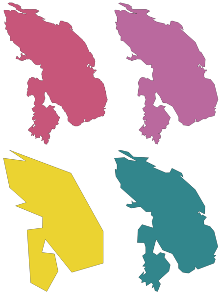
Fig. 24.154 From left to right, source layer and increasing simplification tolerances
Allows features in-place modification
of line and polygon features
Default menu:
See also
Simplify coverage, Smooth, Densify by count, Densify by interval
Parameters
Label |
Name |
Type |
Description |
|---|---|---|---|
Input layer |
|
[vector: line, polygon] |
Input line or polygon vector layer |
Simplification method |
|
[enumeration] Default: 0 |
Simplification method. One of:
|
Tolerance |
|
[numeric: double] Default: 1.0 |
Threshold tolerance (in units of the layer): if the distance between two nodes is smaller than the tolerance value, the segment will be simplified and vertices will be removed. |
Simplified |
|
[same as input] Default: |
Specify the output (simplified) vector layer. One of:
The file encoding can also be changed here. |
Outputs
Label |
Name |
Type |
Description |
|---|---|---|---|
Simplified |
|
[same as input] |
The output (simplified) vector layer |
Python code
Algorithm ID: native:simplifygeometries
import processing
processing.run("algorithm_id", {parameter_dictionary})
The algorithm id is displayed when you hover over the algorithm in the Processing Toolbox. The parameter dictionary provides the parameter NAMEs and values. See Using processing algorithms from the console for details on how to run processing algorithms from the Python console.
24.1.26.74. Single sided buffer
Computes a buffer on lines by a specified distance on one side of the line only.
Buffer always results in a polygon layer.
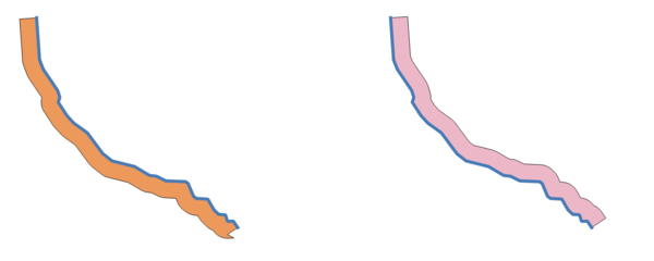
Fig. 24.155 Left versus right side buffer on the same vector line layer
See also
Parameters
Label |
Name |
Type |
Description |
|---|---|---|---|
Input layer |
|
[vector: line] |
Input line vector layer |
Distance |
|
[numeric: double] Default: 10.0 |
Buffer distance. |
Side |
|
[enumeration] Default: 0 |
Which side to create the buffer on. One of:
|
Segments |
|
[numeric: integer] Default: 8 |
Controls the number of line segments to use to approximate a quarter circle when creating rounded offsets. |
Join style |
|
[enumeration] Default: 0 |
Specifies whether round, miter or beveled joins should be used when offsetting corners in a line. Options are:
Fig. 24.156 Round, miter, and bevel join styles |
Miter limit |
|
[numeric: double] Default: 2.0 |
Sets the maximum distance from the offset geometry to use when creating a mitered join as a factor of the offset distance (only applicable for miter join styles). Minimum: 1.0
Fig. 24.157 A 10m buffer with a limit of 2 and a 10m buffer with a limit of 1 |
Buffer |
|
[vector: polygon] Default: |
Specify the output (buffer) layer. One of:
The file encoding can also be changed here. |
Outputs
Label |
Name |
Type |
Description |
|---|---|---|---|
Buffer |
|
[vector: polygon] |
Output (buffer) polygon layer |
Python code
Algorithm ID: native:singlesidedbuffer
import processing
processing.run("algorithm_id", {parameter_dictionary})
The algorithm id is displayed when you hover over the algorithm in the Processing Toolbox. The parameter dictionary provides the parameter NAMEs and values. See Using processing algorithms from the console for details on how to run processing algorithms from the Python console.
24.1.26.75. Smooth
Smooths the geometries in a line or polygon layer by adding more vertices and corners to the feature geometries.
The iterations parameter dictates how many smoothing iterations will be applied to each geometry. A higher number of iterations results in smoother geometries with the cost of greater number of nodes in the geometries.
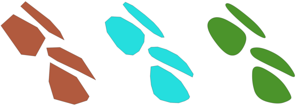
Fig. 24.158 Increasing number of iterations causes smoother geometries
The offset parameter controls how “tightly” the smoothed geometries follow the original geometries. Smaller values results in a tighter fit, and larger values will create a looser fit.
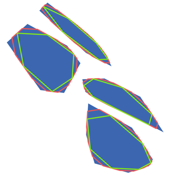
Fig. 24.159 Blue: the input layer. Offset 0.25 gives the red line, while offset 0.50 gives the green line.
The maximum angle parameter can be used to prevent smoothing of nodes with large angles. Any node where the angle of the segments to either side is larger than this will not be smoothed. For example, setting the maximum angle to 90 degrees or lower would preserve right angles in the geometry.
Allows
features in-place modification
of line and polygon features
See also
Simplify, Simplify coverage, Densify by count, Densify by interval
Parameters
Label |
Name |
Type |
Description |
|---|---|---|---|
Input layer |
|
[vector: line, polygon] |
Input line or polygon vector layer |
Iterations |
|
[numeric: integer] Default: 1 |
Increasing the number of iterations will give smoother geometries (and more vertices). |
Offset |
|
[numeric: double] Default: 0.25 |
Increasing values will move the smoothed lines / boundaries further away from the input lines / boundaries. |
Maximum node angle to smooth |
|
[numeric: double] Default: 180.0 |
Every node below this value will be smoothed |
Smoothed |
|
[same as input] Default: |
Specify the output (smoothed) layer. One of:
The file encoding can also be changed here. |
Outputs
Label |
Name |
Type |
Description |
|---|---|---|---|
Smoothed |
|
[same as input] |
Output (smoothed) vector layer |
Python code
Algorithm ID: native:smoothgeometry
import processing
processing.run("algorithm_id", {parameter_dictionary})
The algorithm id is displayed when you hover over the algorithm in the Processing Toolbox. The parameter dictionary provides the parameter NAMEs and values. See Using processing algorithms from the console for details on how to run processing algorithms from the Python console.
24.1.26.76. Snap geometries to layer
Snaps the geometries in a layer either to the geometries from another layer, or to geometries within the same layer.
Matching is done based on a tolerance distance, and vertices will be inserted or removed as required to make the geometries match the reference geometries.
Allows
features in-place modification
of point, line, and polygon features
See also
Parameters
Label |
Name |
Type |
Description |
|---|---|---|---|
Input layer |
|
[vector: geometry] |
Input vector layer |
Reference layer |
|
[vector: geometry] |
Vector layer to snap to |
Tolerance |
|
[numeric: double] Default: 10.0 |
Control how close input vertices need to be to the reference layer geometries before they are snapped. |
Behavior |
|
[enumeration] Default: 0 |
Snapping can be done to an existing node or a segment (its closest point to the vertex to move). Available snapping options:
|
Snapped geometry |
|
[same as input] Default: |
Specify the output (snapped) layer. One of:
The file encoding can also be changed here. |
Outputs
Label |
Name |
Type |
Description |
|---|---|---|---|
Snapped geometry |
|
[same as input] |
Output (snapped) vector layer |
Python code
Algorithm ID: native:snapgeometries
import processing
processing.run("algorithm_id", {parameter_dictionary})
The algorithm id is displayed when you hover over the algorithm in the Processing Toolbox. The parameter dictionary provides the parameter NAMEs and values. See Using processing algorithms from the console for details on how to run processing algorithms from the Python console.
24.1.26.77. Snap points to grid
Modifies the coordinates of geometries in a vector layer, so that all points or vertices are snapped to the closest point of a grid.
If the snapped geometry cannot be calculated (or is totally collapsed) the feature’s geometry will be cleared.
Snapping can be performed on the X, Y, Z or M axis. A grid spacing of 0 for any axis will disable snapping for that axis.
Allows
features in-place modification
of point, line, and polygon features
Warning
Snapping to grid may generate an invalid geometry in some corner cases.
See also
Parameters
Label |
Name |
Type |
Description |
|---|---|---|---|
Input layer |
|
[vector: geometry] |
Input vector layer |
X Grid Spacing |
|
[numeric: double] Default: 1.0 |
Grid spacing on the X axis |
Y Grid Spacing |
|
[numeric: double] Default: 1.0 |
Grid spacing on the Y axis |
Z Grid Spacing |
|
[numeric: double] Default: 0.0 |
Grid spacing on the Z axis |
M Grid Spacing |
|
[numeric: double] Default: 0.0 |
Grid spacing on the M axis |
Snapped |
|
[same as input] Default: |
Specify the output (snapped) layer. One of:
The file encoding can also be changed here. |
Outputs
Label |
Name |
Type |
Description |
|---|---|---|---|
Snapped |
|
[same as input] |
Output (snapped) vector layer |
Python code
Algorithm ID: native:snappointstogrid
import processing
processing.run("algorithm_id", {parameter_dictionary})
The algorithm id is displayed when you hover over the algorithm in the Processing Toolbox. The parameter dictionary provides the parameter NAMEs and values. See Using processing algorithms from the console for details on how to run processing algorithms from the Python console.
24.1.26.78. Split lines by maximum length
Takes a line (or curve) layer and splits each feature into multiple parts, where each part is of a specified maximum length. Z and M values at the start and end of the new line substrings are linearly interpolated from existing values.
Allows
features in-place modification
of line features
Warning
This algorithm drops existing primary keys or FID values and regenerates them in output layers.
Parameters
Label |
Name |
Type |
Description |
|---|---|---|---|
Input layer |
|
[vector: line] |
The input line vector layer |
Maximum line length |
|
[numeric: double] Default: 10.0 |
The maximum length of a line in the output. |
Split |
|
[vector: line] Default: |
Specify the output line vector layer. One of:
The file encoding can also be changed here. |
Outputs
Label |
Name |
Type |
Description |
|---|---|---|---|
Split |
|
[vector: line] |
The new line vector layer.
The length of the feature geometries is less than or equal to the length
specified in the LENGTH parameter. An additional field containing the
|
Python code
Algorithm ID: native:splitlinesbylength
import processing
processing.run("algorithm_id", {parameter_dictionary})
The algorithm id is displayed when you hover over the algorithm in the Processing Toolbox. The parameter dictionary provides the parameter NAMEs and values. See Using processing algorithms from the console for details on how to run processing algorithms from the Python console.
24.1.26.79. Subdivide
Subdivides the geometry. The returned geometry will be a collection containing subdivided parts from the original geometry, where no part has more than the specified maximum number of nodes.
This is useful for dividing a complex geometry into less complex parts, easier to spatially index and faster to perform spatial operations. Curved geometries will be segmentized before subdivision.
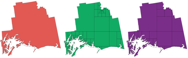
Fig. 24.160 Left the input layer, middle maximum nodes value is 100 and right maximum value is 200
Allows
features in-place modification
of point, line, and polygon features
Note
Subdividing a geometry can generate geometry parts that may not be valid and may contain self-intersections.
See also
Parameters
Label |
Name |
Type |
Description |
|---|---|---|---|
Input layer |
|
[vector: geometry] |
The input vector layer |
Maximum nodes in parts |
|
[numeric: integer] Default: 256 |
Maximum number of vertices each new geometry part is allowed to have. Fewer sub-parts for higher values. |
Subdivided |
|
[same as input] Default: |
Specify the output (subdivided) vector layer. One of:
The file encoding can also be changed here. |
Outputs
Label |
Name |
Type |
Description |
|---|---|---|---|
Subdivided |
|
[same as input] |
Output vector layer |
Python code
Algorithm ID: native:subdivide
import processing
processing.run("algorithm_id", {parameter_dictionary})
The algorithm id is displayed when you hover over the algorithm in the Processing Toolbox. The parameter dictionary provides the parameter NAMEs and values. See Using processing algorithms from the console for details on how to run processing algorithms from the Python console.
24.1.26.80. Swap X and Y coordinates
Switches the X and Y coordinate values in input geometries.
It can be used to repair geometries which have accidentally had their latitude and longitude values reversed.
Allows
features in-place modification
of point, line, and polygon features
Parameters
Label |
Name |
Type |
Description |
|---|---|---|---|
Input layer |
|
[vector: geometry] |
The input vector layer |
Swapped |
|
[same as input] Default: |
Specify the output vector layer. One of:
The file encoding can also be changed here. |
Outputs
Label |
Name |
Type |
Description |
|---|---|---|---|
Swapped |
|
[same as input] |
Output (swapped) vector layer |
Python code
Algorithm ID: native:swapxy
import processing
processing.run("algorithm_id", {parameter_dictionary})
The algorithm id is displayed when you hover over the algorithm in the Processing Toolbox. The parameter dictionary provides the parameter NAMEs and values. See Using processing algorithms from the console for details on how to run processing algorithms from the Python console.
24.1.26.81. Tapered buffers
Creates tapered buffer along line geometries, using a specified start and end buffer diameter.
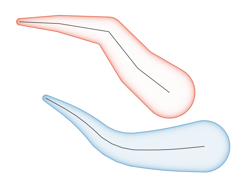
Fig. 24.161 Tapered buffer example
Parameters
Label |
Name |
Type |
Description |
|---|---|---|---|
Input layer |
|
[vector: line] |
Input line vector layer |
Start width |
|
[numeric: double] Default: 0.0 |
Represents the radius of the buffer applied at the start point of the line feature |
End width |
|
[numeric: double] Default: 0.0 |
Represents the radius of the buffer applied at the end point of the line feature. |
Segments |
|
[numeric: integer] Default: 16 |
Controls the number of line segments to use to approximate a quarter circle when creating rounded offsets. |
Buffered |
|
[vector: polygon] Default: |
Specify the output (buffer) layer. One of:
The file encoding can also be changed here. |
Outputs
Label |
Name |
Type |
Description |
|---|---|---|---|
Buffered |
|
[vector: polygon] |
Output (buffer) polygon layer |
Python code
Algorithm ID: native:taperedbuffer
import processing
processing.run("algorithm_id", {parameter_dictionary})
The algorithm id is displayed when you hover over the algorithm in the Processing Toolbox. The parameter dictionary provides the parameter NAMEs and values. See Using processing algorithms from the console for details on how to run processing algorithms from the Python console.
24.1.26.82. Tessellate
Tessellates a polygon geometry layer, dividing the geometries into triangular components.
The output layer consists of multipolygon geometries for each input feature, with each multipolygon consisting of multiple triangle component polygons.
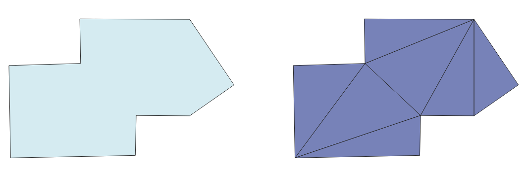
Fig. 24.162 Tessellated polygon (right)
Allows
features in-place modification
of polygon features
Parameters
Label |
Name |
Type |
Description |
|---|---|---|---|
Input layer |
|
[vector: polygon] |
Input polygon vector layer |
Tessellated |
|
[vector: polygon] Default: |
Specify the output layer. One of:
The file encoding can also be changed here. |
Outputs
Label |
Name |
Type |
Description |
|---|---|---|---|
Tessellated |
|
[vector: polygon] |
Output multipolygonZ layer |
Python code
Algorithm ID: 3d:tessellate
import processing
processing.run("algorithm_id", {parameter_dictionary})
The algorithm id is displayed when you hover over the algorithm in the Processing Toolbox. The parameter dictionary provides the parameter NAMEs and values. See Using processing algorithms from the console for details on how to run processing algorithms from the Python console.
24.1.26.83. Transect
Creates transects on vertices for (multi)linestring.
A transect is a line oriented from an angle (by default perpendicular) to the input polylines (at vertices).
The output transect layer includes the original feature fields along with new transect fields.
Warning
This algorithm drops existing primary keys or FID values and regenerates them in output layers.
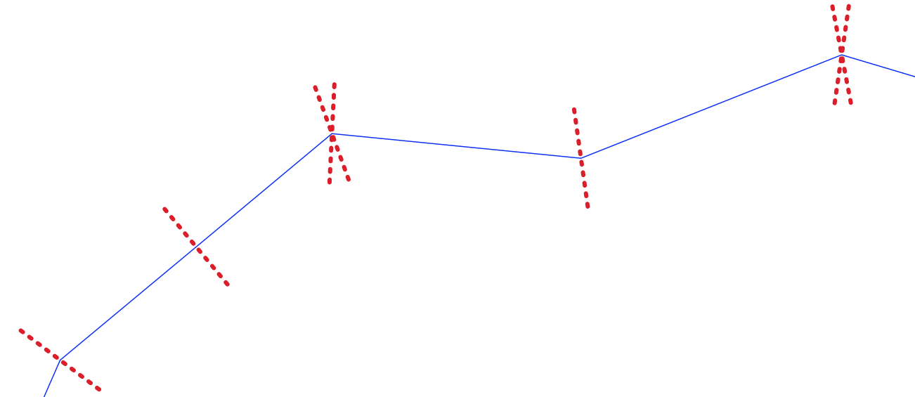
Fig. 24.163 Dashed red lines represent the transect of the input line layer
See also
Parameters
Label |
Name |
Type |
Description |
|---|---|---|---|
Input layer |
|
[vector: line] |
Input line vector layer |
Length of the transect |
|
[numeric: double] Default: 5.0 |
Length in map unit of the transect |
Angle in degrees from the original line at the vertices |
|
[numeric: double] Default: 90.0 |
Change the angle of the transect |
Side to create the transect |
|
[enumeration] |
Choose the side of the transect. Available options are:
|
Direction Optional |
|
[enumeration] Default: |
Orientation direction for transects:
|
Transect |
|
[vector: line] Default: |
Specify the output line layer. One of:
The file encoding can also be changed here. |
Outputs
Label |
Name |
Type |
Description |
|---|---|---|---|
Transect |
|
[vector: line] |
Output line layer. The output layer contains the following fields:
|
Python code
Algorithm ID: native:transect
import processing
processing.run("algorithm_id", {parameter_dictionary})
The algorithm id is displayed when you hover over the algorithm in the Processing Toolbox. The parameter dictionary provides the parameter NAMEs and values. See Using processing algorithms from the console for details on how to run processing algorithms from the Python console.
24.1.26.84. Transect (fixed distance)
Creates transects at fixed distance intervals along (multi)linestrings.
A transect is a line oriented from an angle (by default perpendicular) to the input polylines at regular intervals.
The output transect layer includes the original feature fields along with new transect fields.
Warning
This algorithm drops existing primary keys or FID values and regenerates them in output layers.
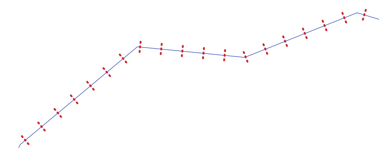
Fig. 24.164 Transects (red lines) created at fixed intervals along the input line layer (blue lines)
See also
Parameters
Label |
Name |
Type |
Description |
|---|---|---|---|
Input layer |
|
[vector: line] |
Input line vector layer |
Fixed sampling interval |
|
[numeric: double] Default: |
Distance between transects along the line |
Length of the transect |
|
[numeric: double] Default: |
Total length of each transect line |
Angle from original line at the vertices |
|
[numeric: double] Default: |
Angle in degrees from the original line. A value of 90° creates perpendicular transects |
Side to create the transects |
|
[enumeration] Default: |
Which side of the line to create transects on (relative to the line digitizing direction):
|
Direction Optional |
|
[enumeration] Default: |
Orientation direction for transects:
|
Transect |
|
[vector: line] Default: |
Specification of the output line layer. One of:
|
Outputs
Label |
Name |
Type |
Description |
|---|---|---|---|
Transect |
|
[vector: line] |
Output line layer containing the generated transects. The output layer contains the following fields:
|
Python code
Algorithm ID: native:transectfixeddistance
import processing
processing.run("algorithm_id", {parameter_dictionary})
The algorithm id is displayed when you hover over the algorithm in the Processing Toolbox. The parameter dictionary provides the parameter NAMEs and values. See Using processing algorithms from the console for details on how to run processing algorithms from the Python console.
24.1.26.85. Translate
Moves the geometries within a layer, by offsetting with a predefined X and Y displacement.
Z and M values present in the geometry can also be translated.
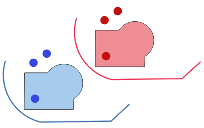
Fig. 24.165 Features in red represent the translated geometry of the input (blue) layer
Allows
features in-place modification
of point, line, and polygon features
Parameters
Label |
Name |
Type |
Description |
|---|---|---|---|
Input layer |
|
[vector: geometry] |
Input vector layer |
Offset distance (x-axis) |
|
[numeric: double] Default: 0.0 |
Displacement to apply on the X axis |
Offset distance (y-axis) |
|
[numeric: double] Default: 0.0 |
Displacement to apply on the Y axis |
Offset distance (z-axis) |
|
[numeric: double] Default: 0.0 |
Displacement to apply on the Z axis |
Offset distance (m values) |
|
[numeric: double] Default: 0.0 |
Displacement to apply on the M axis |
Translated |
|
[same as input] Default: |
Specify the output vector layer. One of:
The file encoding can also be changed here. |
Outputs
Label |
Name |
Type |
Description |
|---|---|---|---|
Translated |
|
[same as input] |
Output vector layer |
Python code
Algorithm ID: native:translategeometry
import processing
processing.run("algorithm_id", {parameter_dictionary})
The algorithm id is displayed when you hover over the algorithm in the Processing Toolbox. The parameter dictionary provides the parameter NAMEs and values. See Using processing algorithms from the console for details on how to run processing algorithms from the Python console.
24.1.26.86. Variable width buffer (by M value)
Creates variable width buffers along lines, using the M value of the line geometries as the diameter of the buffer at each vertex.
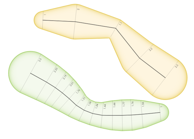
Fig. 24.166 Variable buffer example
See also
Tapered buffers, Buffer, Set M value, Variable distance buffer
Parameters
Label |
Name |
Type |
Description |
|---|---|---|---|
Input layer |
|
[vector: line] |
Input line vector layer |
Segments |
|
[numeric: integer] Default: 16 |
Number of the buffer segments per quarter circle. It can be a unique value (same value for all the features), or it can be taken from features data (the value can depend on feature attributes). |
Buffered |
|
[vector: polygon] Default: |
Specify the output (buffer) layer. One of:
The file encoding can also be changed here. |
Outputs
Label |
Name |
Type |
Description |
|---|---|---|---|
Buffered |
|
[vector: polygon] |
Variable buffer polygon layer |
Python code
Algorithm ID: native:bufferbym
import processing
processing.run("algorithm_id", {parameter_dictionary})
The algorithm id is displayed when you hover over the algorithm in the Processing Toolbox. The parameter dictionary provides the parameter NAMEs and values. See Using processing algorithms from the console for details on how to run processing algorithms from the Python console.
24.1.26.87. Voronoi polygons
Takes a point layer and generates a polygon layer containing the Voronoi polygons (known also as Thiessen polygons) corresponding to those input points.
Any location within a Voronoi polygon is closer to the associated point than to any other point.
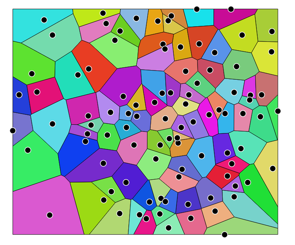
Fig. 24.167 Voronoi polygons
Default menu:
Parameters
Label |
Name |
Type |
Description |
|---|---|---|---|
Input layer |
|
[vector: point] |
Input point vector layer |
Buffer region (% of extent) |
|
[numeric: double] Default: 0.0 |
The extent of the output layer will be this much bigger than the extent of the input layer |
Tolerance Optional
|
|
[numeric: double] Default: 0.0 |
Specifies an optional snapping tolerance which can be used to improve the robustness of the voronoi. |
Copy attributes from input features
|
|
[boolean] Default: True |
Specifies whether fields storing involved point features ID should be added to the output.
If False, an |
Voronoi polygons |
|
[vector: polygon] Default: |
Specify the output layer (with the Voronoi polygons). One of:
The file encoding can also be changed here. |
Outputs
Label |
Name |
Type |
Description |
|---|---|---|---|
Voronoi polygons |
|
[vector: polygon] |
Voronoi polygons of the input point vector layer |
Python code
Algorithm ID: native:voronoipolygons
import processing
processing.run("algorithm_id", {parameter_dictionary})
The algorithm id is displayed when you hover over the algorithm in the Processing Toolbox. The parameter dictionary provides the parameter NAMEs and values. See Using processing algorithms from the console for details on how to run processing algorithms from the Python console.