The Open Geospatial Consortium (OGC) is an international organization with membership of more
than 300 commercial, governmental, nonprofit and research organizations worldwide.
Its members develop and implement standards for geospatial content and services,
GIS data processing and exchange.
Describing a basic data model for geographic features, an increasing number
of specifications are developed by OGC to serve specific needs for interoperable
location and geospatial technology, including GIS. Further information
can be found at https://www.ogc.org/.
Important OGC specifications supported by QGIS are:
SensorThings API — SensorThings API (SensorThings)
OGC services are increasingly being used to exchange geospatial data between
different GIS implementations and data stores. QGIS can deal with the above
specifications as a client, being SFS (through support of the PostgreSQL
data provider, see section PostgreSQL Database).
You can also share your maps and data through the WMS, WMTS, WFS, WFS-T and WCS protocols
using a webserver with QGIS Server, UMN MapServer or
GeoServer installed.
QGIS currently can act as a WMS client that understands WMS 1.1, 1.1.1
and 1.3 servers. In particular, it has been tested against publicly accessible
servers such as DEMIS.
A WMS server acts upon requests by the client (e.g., QGIS) for a raster map
with a given extent, set of layers, symbolization style, and transparency.
The WMS server then consults its local data sources, rasterizes the map,
and sends it back to the client in a raster format. For QGIS, this format would
typically be JPEG or PNG.
WMS is generically a REST (Representational State Transfer) service rather
than a full-blown Web service. As such, you can actually take the URLs
generated by QGIS and use them in a web browser to retrieve the same images
that QGIS uses internally. This can be useful for troubleshooting, as there
are several brands of WMS server on the market and they all have their
own interpretation of the WMS standard.
WMS layers can be added quite simply, as long as you know the URL to access
the WMS server, you have a serviceable connection to that server, and the
server understands HTTP as the data transport mechanism.
Additionally, QGIS will cache your WMS responses (i.e. images) for 24h as long
as the GetCapabilities request is not triggered. The GetCapabilities request is
triggered every time the Connect button in the WMS/WMTS
dialog is used to retrieve the WMS server capabilities. This is an automatic
feature meant to optimize project loading time. If a project is saved with a WMS layer,
the corresponding WMS tiles will be loaded from the cache the next time the project is opened
as long as they are not older than 24h.
QGIS can also act as a WMTS client. WMTS is an OGC standard for distributing
tile sets of geospatial data. This is a faster and more efficient way of
distributing data than WMS because with WMTS, the tile sets are pre-generated,
and the client only requests the transmission of the tiles, not their
production. A WMS request typically involves both the generation and
transmission of the data. A well-known example of a non-OGC standard for
viewing tiled geospatial data is Google Maps.
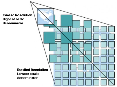
In order to display the data at a variety of scales close to what the user
might want, the WMTS tile sets are produced at several different scale levels
and are made available for the GIS client to request them.
This diagram illustrates the concept of tile sets:
The two types of WMTS interfaces that QGIS supports are via Key-Value-Pairs
(KVP) and RESTful. These two interfaces are different, and you need to specify
them to QGIS differently.
In order to access a WMTS KVP service, a QGIS user must open the WMS/WMTS interface
and add the following string to the URL of the WMTS tile service:
For testing the topo2 layer in this WMTS works nicely. Adding this string indicates
that a WMTS web service is to be used instead of a WMS service.
The RESTful WMTS service takes a different form, a straightforward URL.
The format recommended by the OGC is:
{WMTSBaseURL}/1.0.0/WMTSCapabilities.xml
This format helps you to recognize that it is a RESTful address. A RESTful WMTS is
accessed in QGIS by simply adding its address in the WMS setup in the URL field of
the form. An example of this type of address for the case of an Austrian basemap is:
You can still find some old services called WMS-C. These services are quite similar
to WMTS (i.e., same purpose but working a little bit differently). You can manage
them the same as you do WMTS services. Just add ?tiled=true at the end
of the url. See https://wiki.osgeo.org/wiki/Tile_Map_Service_Specification for more
information about this specification.
When you read WMTS, you can often think WMS-C also.
Name: A name for the connection. This name will be used in
the Server Connections drop-down box so that you can distinguish it from
other WMS servers.
URL: URL of the server providing the data. This must be a
resolvable host name – the same format as you would use to open a telnet
connection or ping a host, i.e. the base URL only.
For example, you shouldn’t have fragments such as request=GetCapabilities
or version=1.0.0 in your URL.
Authentication (optional): using a stored configuration or a basic authentication with
Username and Password.
Warning
Entering username and password in the Authentication
tab will keep unprotected credentials in the connection configuration.
Those credentials will be visible if, for instance, you shared the
project file with someone. Therefore, it’s advisable to save your
credentials in an Authentication configuration instead
(Configurations tab).
See Authentication System for more details.
HTTP Referer
Default Image Format: Detects the available image formats from the server,
allows you to set a preferred one and stores it in the connection settings.
WMS DPI-Mode: Available options are all, off, QGIS,
UMN and GeoServer
WMTS server-side tile pixel ratio: When rendering WMTS layers,
allows to scale up or down the tiles based on the device screen DPI.
Available options are Undefined (not scaled),
Standard (96 DPI) and High (192 DPI).
Maximum number of GetFeatureInfo results: specifies a default value
for the maximum number of results returned per layer by a GetFeatureInfo request
using this connection (see FEATURE_COUNT parameter).
Default value is 10.
Set to 0 to use server default value (usually 1): no FEATURE_COUNT parameter will be added to the request.
Ignore GetMap/GetTile/GetLegendGraphic URI reported in capabilities:
if checked, use given URI from the URL field above.
Ignore GetFeatureInfo URI reported in capabilities:
if checked, use given URI from the URL field above.
Ignore reported layer extents: because the extent
reported by raster layers may be smaller than the actual area which can
be rendered (notably for WMS servers with symbology which takes more space
than the data extent), check this option to avoid cropping raster layers
to their reported extents, resulting in truncated symbols on the borders
of these layers.
Ignore axis orientation (WMS 1.3/WMTS)
Invert axis orientation
Smooth pixmap transformation
Press OK
Once the new WMS/WMTS server connection has been created, it will be preserved for
future QGIS sessions.
Note that it is also possible to Load the connection parameters
from a .XML file or Save them to a .XML file.
If you need to set up a proxy server to be able to receive WMS services from the
internet, you can add your proxy server in the options. Choose
Settings ► Options and click on the Network tab.
There, you can add your proxy settings and enable them by setting Use proxy for web access. Make sure that you select the correct
proxy type from the Proxy type drop-down menu.
Once you have successfully filled in your parameters, you can use the
Connect button to retrieve the capabilities of the selected server.
This includes the image encoding, layers, layer styles and projections.
Since this is a network operation, the speed of the response depends on the
quality of your network connection to the WMS server.
While downloading data from the WMS server, the download progress is
visualized in the lower left corner of the main QGIS dialog.
Your screen should now look a bit like Fig. 19.3,
which shows the response provided by a WMS server.
Fig. 19.3 Dialog for adding a WMS server, with filter on available layers
The upper part of the Layers tab of the dialog shows a tree
structure that can include layer groups embedding layers with their associated
image style(s) served by the server.
Each item can be identified by:
an ID
a Name
a Title
and an Abstract.
The list can be filtered using the widget in the top right corner.
Image Encoding
The Image encoding section lists the formats that are supported
by both the client and server. Choose one depending on your image accuracy
requirements.
Tip
Image Encoding
You will typically find that a WMS server offers you the choice of JPEG
or PNG image encoding. JPEG is a lossy compression format, whereas PNG
faithfully reproduces the raw raster data.
Use JPEG if you expect the WMS data to be photographic in nature and/or
you don’t mind some loss in picture quality. This trade-off typically
reduces by five times the data transfer requirement compared with PNG.
Use PNG if you want precise representations of the original data and you
don’t mind the increased data transfer requirements.
Options
The Options area of the dialog provides means to configure the WMS requests.
You can define:
Tile size if you want to set tile sizes (e.g., 256x256)
to split up the WMS request into multiple requests.
Request step size: if you want to reduce the effect of cut labels at tile borders,
increasing the step size creates larger requests, fewer tiles and fewer borders.
The default value is 2000.
The Maximum number of GetFeatureInfo results: specifies the maximum number of results
returned by a GetFeatureInfo request, for the layer(s) being loaded.
Allows to override the connection’s default value for specific layers.
Each WMS layer can be presented in multiple CRSs, depending on the capability of
the WMS server. If you select a WMS from the list, a field with the default projection
provided by the web server appears. Press the Select CRS widget
to replace the default projection of the WMS with another CRS supported by the WMS server.
A dialog similar to the one shown in Fig. 6.4 will appear.
The main difference with the WMS version of the dialog is that only
those CRSs supported by the WMS server will be shown.
Finally you can activate Use contextual WMS Legend if the
WMS Server supports this feature. Then only the relevant legend for your current
map view extent will be shown and thus will not include legend items for items
you can’t see in the current map.
You can select several layers at once, but only one image style per layer.
When several layers are selected, they will be combined at the WMS server
and transmitted to QGIS in one go, as a single layer.
The default name is a slash (/) separated list of their original title.
You can however opt to Load as separate layers,
in which case each layer is added to the map canvas using its default name
from the queried service.
Layer Order
The Layer Order tab lists the selected layers available from the
current connected WMS server.
WMS layers rendered by a server are overlaid in the order listed in the
Layers tab, from top to bottom of the list.
If you want to change the overlay order, you can use the Up
and Down buttons of the Layer Order tab.
Transparency
The Global transparency setting from the
Layer Properties is hard coded to be always on, where available.
When using WMTS (Cached WMS) services you are able to browse through
the Tilesets tab given by the server.
Additional information like tile size, formats and supported CRS are listed in
this table.
# example of WMTS service

https://opencache.statkart.no/gatekeeper/gk/gk.open_wmts?service=WMTS&request=GetCapabilities
Selecting a layer to load, it is also possible to apply an
Interpretation method, converting it into a raster layer
of single band float type, ready for styling using QGIS usual
raster renderers.
In combination with this feature, you can use the tile scale slider
by selecting View ► Panels ( or Settings
► Panels), then choosing Tile Scale Panel. This gives you the
available scales from the tile server with a nice slider docked in.
Once you have added a WMS server, and if any layer from a WMS server is queryable,
you can then use the Identify tool to select a pixel on
the map canvas. A query is made to the WMS server for each selection made.
The results of the query are returned in plain text. The formatting of this text
is dependent on the particular WMS server used.
Format selection
If multiple output formats are supported by the server, a combo box with supported
formats is automatically added to the identify results dialog and the selected
format may be stored in the project for the layer.
GML format support
The Identify tool supports WMS server response
(GetFeatureInfo) in GML format (it is called Feature in the QGIS GUI in this context).
If “Feature” format is supported by the server and selected, results of the Identify
tool are vector features, as from a regular vector layer. When a single feature
is selected in the tree, it is highlighted in the map and it can be copied to
the clipboard and pasted to another vector layer. See the example setup of the
UMN Mapserver below to support GetFeatureInfo in GML format.
# in layer METADATA add which fields should be included and define geometry (example):"gml_include_items""all""ows_geometries""mygeom""ows_mygeom_type""polygon"# Then there are two possibilities/formats available, see a) and b):# a) basic (output is generated by Mapserver and does not contain XSD)# in WEB METADATA define formats (example):"wms_getfeatureinfo_formatlist""application/vnd.ogc.gml,text/html"# b) using OGR (output is generated by OGR, it is sent as multipart and contains XSD)# in MAP define OUTPUTFORMAT (example):OUTPUTFORMATNAME"OGRGML"MIMETYPE"ogr/gml"DRIVER"OGR/GML"FORMATOPTION"FORM=multipart"END# in WEB METADATA define formats (example):"wms_getfeatureinfo_formatlist""OGRGML,text/html"
Once you have added a WMS server, you can view its properties by right-clicking
on it in the legend and selecting Properties.
The WMS/WMTS layer properties is much like the raster layer properties
so you will find detailed description at Raster Properties Dialog.
However, there are some differences, which will be explained below.
The tab Metadata displays a wealth of information about the WMS server,
generally collected from the capabilities statement returned from that server.
Many definitions can be gleaned by reading the WMS standards
(see OPEN-GEOSPATIAL-CONSORTIUM in Literature and Web References),
but here are a few handy definitions:
Server Properties
WMS Version — The WMS version supported by the server.
Image Formats — The list of MIME-types the server can respond with
when drawing the map. QGIS supports whatever formats the underlying Qt
libraries were built with, which is typically at least image/png and
image/jpeg.
Identity Formats — The list of MIME-types the server can respond
with when you use the Identify tool. Currently, QGIS supports the
text-plain type.
Layer Properties
Selected — Whether or not this layer was selected when its server was
added to this project.
Visible — Whether or not this layer is selected as visible in the
legend (not yet used in this version of QGIS).
Can Identify — Whether or not this layer will return any results
when the Identify tool is used on it.
Can be Transparent — Whether or not this layer can be rendered with
transparency. This version of QGIS will always use transparency if this is
Yes and the image encoding supports transparency.
Can Zoom In — Whether or not this layer can be zoomed in by the server.
This version of QGIS assumes all WMS layers have this set to Yes.
Deficient layers may be rendered strangely.
Cascade Count — WMS servers can act as a proxy to other WMS servers to
get the raster data for a layer. This entry shows how many times the request
for this layer is forwarded to peer WMS servers for a result.
Fixed Width, Fixed Height — Whether or not this layer has fixed source
pixel dimensions. This version of QGIS assumes all WMS layers have this set
to nothing. Deficient layers may be rendered strangely.
WGS 84 Bounding Box — The bounding box of the layer, in WGS 84
coordinates. Some WMS servers do not set this correctly (e.g., UTM coordinates
are used instead). If this is the case, then the initial view of this layer
may be rendered with a very ‘zoomed-out’ appearance by QGIS. The WMS webmaster
should be informed of this error, which they may know as the WMS XML elements
LatLonBoundingBox, EX_GeographicBoundingBox or the CRS:84 BoundingBox.
Available in CRS — The projections that this layer can be rendered
in by the WMS server. These are listed in the WMS-native format.
Available in style — The image styles that this layer can be rendered
in by the WMS server.
Raster temporal properties (namely Dynamic Temporal Control)
can be set for WMS and WMTS layers.
By default, when a time-dimension enabled WMS or WMTS layer is added to the project,
it is indicated in the Layers panel
with the Temporal Layer icon next to it.
Its Temporal properties default to the Automatic temporal mode,
meaning that the layer will follow the temporal controller’s current time range by default.
You can then opt to show a specific static time value for the layer
by unchecking Dynamic Temporal Control
and picking an option under Static WMS-T Temporal Range:
Server default
Predefined date with a server exposing data for non-contiguous temporal ranges
or Predefined range with a server exposing a range of available dates.
A Start date and End date are necessary in the latter case.
Their expected formatting can be deduced from the reference time option (see below).
depending on whether the provider has data for contiguous period or not
Follow project’s temporal range as defined in the project’s properties dialog
Whatever temporal data control is in use, there are some WMS-T Settings
to help display the correct temporal data:
Time slice mode which can be:
Use whole temporal range
Match to start of range
Match to end of range
Closest match to start of range
Closest match to end of range
Ignore time components (use dates only):
If checked, the time component of temporal queries will be discarded
and only the date component will be used in server requests.
You can also Use Specific WMS-T Reference Time
picked from times reported in the layer’s capabilities.
Convenient for servers which expose a non-contiguous set of date time instances
(instead of a range of dates).
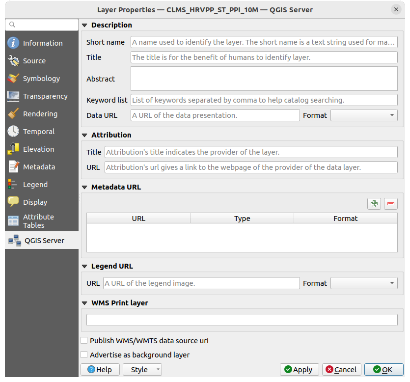
In addition to the raster layer properties,
publishing a WMS/WMTS layer with QGIS Server will display following options:
WMS Print layer: Allows to set alternative WMS layer
that should be used for printing (in the GetProjectSettings reply).
Convenient for WMTS layers that are generally not suitable for printing.
Publish WMS/WMTS data source uri:
Allows a web client to fetch the WMS/WMTS data directly
Advertise as background layer
Fig. 19.5 QGIS Server properties of a WMS/WMTS layer
The QGIS WMS data provider is able to display a legend graphic in the table of
contents’ layer list and in the print layout. The WMS legend will be shown only
if the WMS server has GetLegendGraphic capability and the layer has
getCapability url specified, so you additionally have to select a styling for the
layer.
If a legendGraphic is available, it is shown below the layer. It is little and
you have to click on it to open it in real dimension (due to QgsLegendInterface
architectural limitation). Clicking on the layer’s legend will open a frame with
the legend at full resolution.
In the print layout, the legend will be integrated at it’s original (downloaded)
dimension. Resolution of the legend graphic can be set in the item properties
under Legend ► WMS LegendGraphic to match your printing
requirements.
The legend will display contextual information based on your current scale. The
WMS legend will be shown only if the WMS server has GetLegendGraphic capability
and the layer has getCapability url specified, so you have to select a styling.
A Web Coverage Service (WCS) provides access to raster data in forms that are useful
for client-side rendering, as input into scientific models, and for other clients.
The WCS may be compared to the WFS and the WMS. As WMS and WFS service instances, a
WCS allows clients to choose portions of a server’s information holdings based on
spatial constraints and other query criteria.
QGIS has a native WCS provider and supports both version 1.0 and 1.1 (which are significantly
different), but currently it prefers 1.0, because 1.1 has many issues (i.e., each server implements it
in a different way with various particularities).
The native WCS provider handles all network requests and uses all standard QGIS
network settings (especially proxy). It is also possible to select cache mode
(‘always cache’, ‘prefer cache’, ‘prefer network’, ‘always network’), and the provider also
supports selection of time position, if temporal domain is offered by the server.
Loading a WCS Layer
To be able to load a WCS Layer, first create a connection to the WCS server:
Open the Data Source Manager dialog by pressing the
Open Data Source Manager button
Enable the WCS tab
Click on New… to open the Create a New WCS
Connection dialog
Name: A name for the connection. This name will be used in
the Server Connections drop-down box so that you can distinguish it from
other WCS servers.
URL: URL of the server providing the data. This must be a
resolvable host name – the same format as you would use to open a telnet
connection or ping a host, i.e. the base URL only.
For example, you shouldn’t have fragments such as request=GetCapabilities
or version=1.0.0 in your URL.
Authentication (optional): using a stored configuration or a basic authentication with
Username and Password.
Warning
Entering username and password in the Authentication
tab will keep unprotected credentials in the connection configuration.
Those credentials will be visible if, for instance, you shared the
project file with someone. Therefore, it’s advisable to save your
credentials in an Authentication configuration instead
(Configurations tab).
See Authentication System for more details.
HTTP Referer
Ignore GetCoverage URI reported in capabilities:
if checked, use given URI from the URL field above.
Ignore reported layer extents: because the extent
reported by raster layers may be smaller than the actual area which can
be rendered (notably for WCS servers with symbology which takes more space
than the data extent), check this option to avoid cropping raster layers
to their reported extents, resulting in truncated symbols on the borders
of these layers.
Ignore axis orientation
Invert axis orientation
Smooth pixmap transformation
Press OK to create the connection.
Note that any proxy settings you may have set in your preferences are also recognized.
Also note that it is possible to Load the connection parameters
from a .XML file or Save them to a .XML file.
Now we are ready to load WCS layers from the above connection.
In QGIS, a WFS layer behaves pretty much like any other vector layer.
You can identify and select features, and view the attribute table.
QGIS supports WFS 1.0.0, 1.1.0, 2.0 and OGC API - Features (OAPIF),
including editing (through WFS-T).
QGIS also supports background download and progressive rendering,
on-disk caching of downloaded features and version autodetection.
Layers of servers implementing OGC API - Features - Part 4: Create, Replace,
Update and Delete can be turned into
editing mode to allow creating, modifying and deleting features. Note that each
created/modified/deleted feature requires a dedicated network request, so
performance might suffer in case of simultaneous modification of hundreds or
more features at a time.
In general, adding a WFS layer is very similar to the procedure used with WMS.
There are no default servers defined, so you have to add your own.
You can find WFS servers by using the MetaSearch plugin
or your favourite web search engine.
There are a number of lists with public URLs, some of them maintained
and some not.
Loading a WFS Layer
As an example, we use the Gateway Geomatics WFS server and display a layer.
In case of an OGC API - Features (OAPIF), the URL to provide should
be the landing page, i.e., the main page from which
it is possible to navigate to all the available service endpoints.
In the WFS Options group, you can:
Indicate the WFS version of the server.
If unknown, press the Detect button to automatically retrieve it.
Set Feature format to select the format used to download OAPIF features
(for example, GeoJSON or FlatGeoBuf). Click Detect to check the available
format(s) from the server.
Select the Preferred HTTP method to use for requests.
The default is GET, but you can also select POST.
Define the Maximum number of features retrieved in a single GetFetFeature request.
If empty, no limit is set.
Feature mode (simple vs complex): helps determine how to handle servers
serving data with simple or complex GML schemas. Available options are:
Default: if the server supports editing capabilities, this is the same
as using Simple Features. If not, it fallbacks to using Complex Features mode.
Simple Features: returns data as simple features only
Complex Features: uses the OGR GMLAS <https://gdal.org/en/stable/drivers/vector/gmlas.html>,
potentially returning complex features, depending on the data schema,
where nested data structures are exposed by QGIS as JSON.
Depending on the WFS version, indicate whether to:
Enable Feature paging and specify the maximum number of features
to retrieve with Page size.
If no limit is defined, then the server default is applied.
Force to Ignore axis orientation (WFS 1.1/WFS 2.0)
Invert axis orientation.
Use GML2 encoding for transactions.
Force initial GetFeature:
When checked, an initial GetFeature call will always be issued
in order to determine the geometry type from the first downloaded feature.
Because QGIS assumes features are of 2D geometry type, use this option
if the layer contains features with Z axis coordinates you would like to get
(and possibly edit in WFS-T).
Warning
Entering username and password in the Authentication
tab will keep unprotected credentials in the connection configuration.
Those credentials will be visible if, for instance, you shared the
project file with someone. Therefore, it’s advisable to save your
credentials in an Authentication configuration instead
(Configurations tab). See Authentication System for
more details.
Press OK to create the connection.
Note that any proxy settings you may have set in your preferences are also recognized.
Also note that it is possible to Load the connection parameters
from a .XML file or Save them to a .XML file.
Now we are ready to load WFS layers from the above connection.
Choose ‘Gateway Geomatics’ from the Server Connections drop-down list.
Click Connect
Select the Parks layer in the list
You can also choose whether to:
Only request features overlapping the view extent
Change… the layer’s CRS to any other supported by the service
or build a query to specify particular features to retrieve from the service:
double-click on the row of the layer to open the SQL Query Composer dialog.
That dialog provides widgets to write an advanced SQL query relying on available
tables and columns of the service, with sorting and filtering
and a bunch of SQL functions, spatial predicates and operators.
The query you build will appear after validation in the SQL column
within the WFS / OGC API - Features table, and the filtered layer will display
the icon next to it in the Layers panel.
It is thus possible to adjust the query at any moment.
Click Add to add the layer to the map,
using its default name from the queried service.
You’ll notice the download progress is visualized in the lower left of the QGIS
main window. Once the layer is loaded, you can identify and select a couple of
features and view the attribute table.
QGIS supports connections to OGC SensorThings API,
a standard providing an open and unified framework to interconnect IoT sensing devices,
data, and applications over the Web.
It is an open standard addressing the syntactic and semantic interoperability of the Internet of Things.
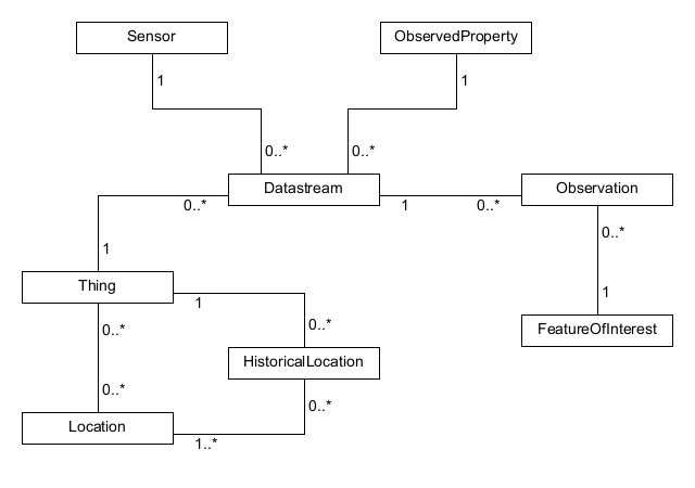
It is based on the Observations and Measurements data model,
a standardized model for observations, and for features involved in sampling when making observations.
To add SensorThings data to QGIS use the SensorThings
tab in the Data Source Manager dialog.
To establish a new connection, press New (or New SensorThings Connection
from the Browser panel) and provide Name and URL.
Advanced options, such as authentication and
a Referer, can also be configured.
Press OK to establish the connection.
Then you will be able to:
Configurations can be saved to an .XML file (Save)
through the SensorThings entry in Data Source Manager dialog
or its contextual menu in the Browser panel (Save Connections).
Likewise, configurations can be added from a file (Load).
Any type of entity can be loaded in QGIS, but not all are spatial data.
To load an entity, there are Layer Settings that can be configured:
Entity Type: the entity to load from the data model as layer in QGIS
Geometry Type: the geometry type of the selected entity to load.
Press Check available types to limit the list to the actually
supported geometry types.
Page Size
Feature Limit sets a maximum number of features to request from the service
Extent Limit sets a maximum extent limit for the layer, so that only features
within the extent are requested
Expansions: The data model of SensorThings provides a mechanism of expansion
of the results to related entities, similar to how tables are joined together in a relational database.
Using this approach, you can expand the selected layer to include data from other items.
This will flatten the relationship, creating as many parent features as children,
and additional properties are added as columns in the attribute table.
Use Filter to build a query to filter the data, using SensorThings filter syntax.
Note
The above settings and filtering options are also available
for update in the layer properties dialog, Source tab, once loaded in QGIS.
Press Add to load the selected entity type as layer in QGIS.
A SensorThings layer is loaded in QGIS as a vector layer.
As such, it displays the same tabs in the layer properties
and allows same feature interactions using the selection or identify tools.
There are however some specificities you should consider while working with SensorThings data.
Because of the data model, the result property of a SensorThings Observation is a string field.
In case you want to use its numerical representation in for example a graduated style,
use an expression to convert the value to real and try() in case this fails
(e.g., try(to_real("Observation_result"),Null)).
In case you want to create a chart of the observations at one or more locations,
you can install the QGIS plugin Data Plotly.
Now select the observations at a point location in the map view.
Open the plotly panel and activate the Use only selected features checkbox.
Select on the x-column a date-time property and on the y-column the Observation_result.
This will plot the observations at that location over time.
Verify to filter by a single Observed Property.
Notice that the chart changes as soon as you select other locations on the map.
Fig. 19.11 Use Data plotly to plot the air quality observations at a location
STAC (SpatioTemporal Asset Catalog) is a specification for describing geospatial
data in a consistent and accessible way. It defines a standard structure for organizing
and indexing spatial-temporal assets such as satellite imagery, drone photos, or sensor data
so that you can search, preview, and use these datasets across different platforms and tools.
STAC enables QGIS users to connect to and browse geospatial datasets, either from static catalogs
or dynamic APIs, and download or stream assets such as imagery or other spatial data.
STAC Items: The basic unit of a STAC catalog. Each item represents one geospatial
asset or a group of related assets (e.g. image bands) at a specific time and location.
It includes metadata such as geometry, datetime, links to assets (e.g., TIFFs, JSON, COG), and properties.
STAC Collections: A grouping of items that share common characteristics and metadata (e.g. satellite mission).
Collections may define spatial and temporal extents, licensing, and keywords.
STAC Catalogs: A hierarchical container that organizes items and/or collections.
Catalogs allow navigation of STAC datasets but do not necessarily include search capabilities.
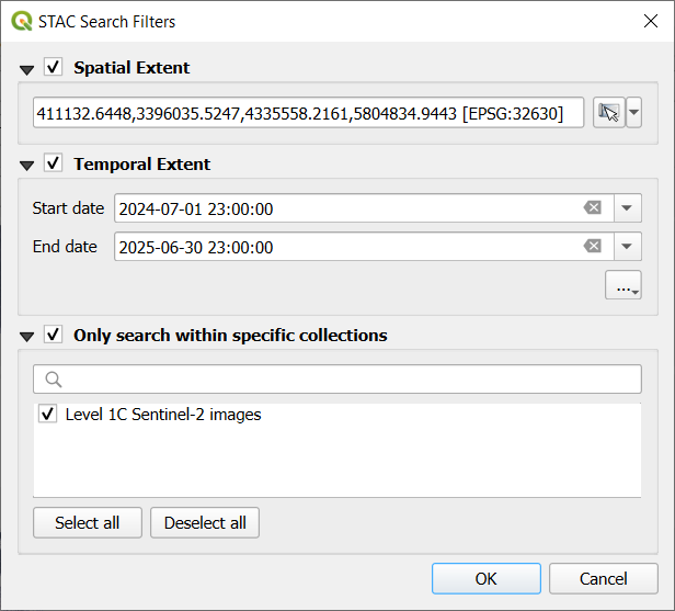
STAC API: An implementation of the STAC specification that allows querying and filtering of STAC items using spatial
and temporal based filters, as well as searching within specific collections.
STAC APIs follow the OGC API - Features pattern and support dynamic access to datasets.
There is an important distinction between static STAC catalogs and STAC API endpoints:
Static STAC Catalogs: are collections of JSON files without search capabilities.
They can be browsed via the Browser panel.
STAC API: provide search capabilities and can be accessed in QGIS through both
the Browser panel and the Data Source Manager.
STAC connections can be added in QGIS using either the Browser panel or the Data Source Manager:
Browser Panel:
In the Browser panel, right-click on the STAC entry and select New STAC Connection….
In the dialog that appears, enter a Name for the connection, the URL of the STAC catalog
and optionally fill in Authentication credentials and a Referer.
Then click OK.
Use this method for browsing static STAC catalogs that do not support search or filtering.
Data Source Manager:
For STAC APIs you can use Data Source Manager dialog.
Open the Data Source Manager, choose the STAC tab
and click the New button.
Fill in the Name and URL fields, and (optional)
the Authentication credentials and a Referer.
Press OK and then
Connect to establish the connection, after that you will be able to:
Edit the STAC connection settings
Remove the STAC connection
Fig. 19.12 Creating a connection to a STAC server
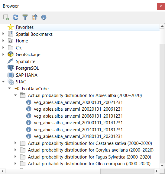
Static STAC catalogs are displayed as hierarchical structures within the Browser panel.
Once connected, the STAC catalog appears under STAC in the Browser panel.
You can expand the catalog node to see its Collections.
Expanding a collection reveals the individual Items it contains.
Fig. 19.13 STAC connection expanded in the Browser, showing Collections and Items
Right-click any STAC Item and choose Details… to view its metadata.
The details panel shows the item’s JSON content and a map of its coverage.
If an item’s asset is a cloud-optimized format (e.g. a .COG),
you can add it directly to the map canvas.
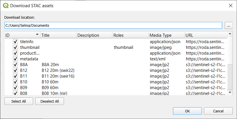
Otherwise, Download Assets… to save it locally before use.
Downloaded assets include the main dataset and any auxiliary files such as thumbnails or style files.
After download, use standard QGIS tools (e.g., Add Raster Layer…) to load and display the data.
An ArcGIS REST Server can host many different types of web services
(feature service, map service, image service, …).
Read Using ArcGIS REST Servers for instructions to connect to an ArcGIS REST server.
When loading layers from an ArcGIS Feature Service,
symbols are automatically converted to QGIS-native symbology,
allowing QGIS to visually reproduce the same appearance as ArcGIS web maps.
Layers from an ArcGIS Feature Service can be editable in QGIS if:
The ArcGIS service has editing enabled
Your credentials grant write access
And the remote layer supports editing operations (Create, Update, or Delete capabilities).
If these options are disabled on the server, the layer will be read-only in QGIS.
Editing these layers follow the same procedure
as for other vector layers.
To update your map with the latest changes, use View ► Refresh or press F5.
If multiple users edit the same layer concurrently, it is recommended to refresh your data
before performing edits to avoid conflicts.
 WMS/WMTS tab of the Data Source
Manager dialog, either by:
WMS/WMTS tab of the Data Source
Manager dialog, either by: Open Data Source Manager button
(or pressing Ctrl+L) and enabling the tab
Open Data Source Manager button
(or pressing Ctrl+L) and enabling the tab Add WMS layer button on the
Manage Layers toolbar
Add WMS layer button on the
Manage Layers toolbar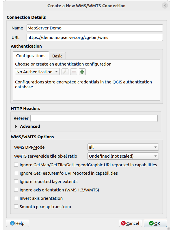
 Ignore GetMap/GetTile/GetLegendGraphic URI reported in capabilities:
if checked, use given URI from the URL field above.
Ignore GetMap/GetTile/GetLegendGraphic URI reported in capabilities:
if checked, use given URI from the URL field above. Use proxy for web access. Make sure that you select the correct
proxy type from the Proxy type
Use proxy for web access. Make sure that you select the correct
proxy type from the Proxy type  drop-down menu.
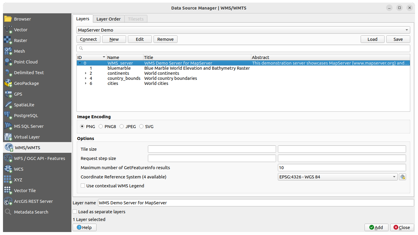
 widget in the top right corner.
 Select CRS widget
to replace the default projection of the WMS with another CRS supported by the WMS server.
Select CRS widget
to replace the default projection of the WMS with another CRS supported by the WMS server. ), then choosing Tile Scale Panel. This gives you the
available scales from the tile server with a nice slider docked in.
), then choosing Tile Scale Panel. This gives you the
available scales from the tile server with a nice slider docked in. Identify tool to select a pixel on
the map canvas. A query is made to the WMS server for each selection made.
The results of the query are returned in plain text. The formatting of this text
is dependent on the particular WMS server used.
Identify tool to select a pixel on
the map canvas. A query is made to the WMS server for each selection made.
The results of the query are returned in plain text. The formatting of this text
is dependent on the particular WMS server used. Temporal Layer icon next to it.
Its Temporal properties default to the Automatic temporal mode,
meaning that the layer will follow the temporal controller’s current time range by default.
Temporal Layer icon next to it.
Its Temporal properties default to the Automatic temporal mode,
meaning that the layer will follow the temporal controller’s current time range by default.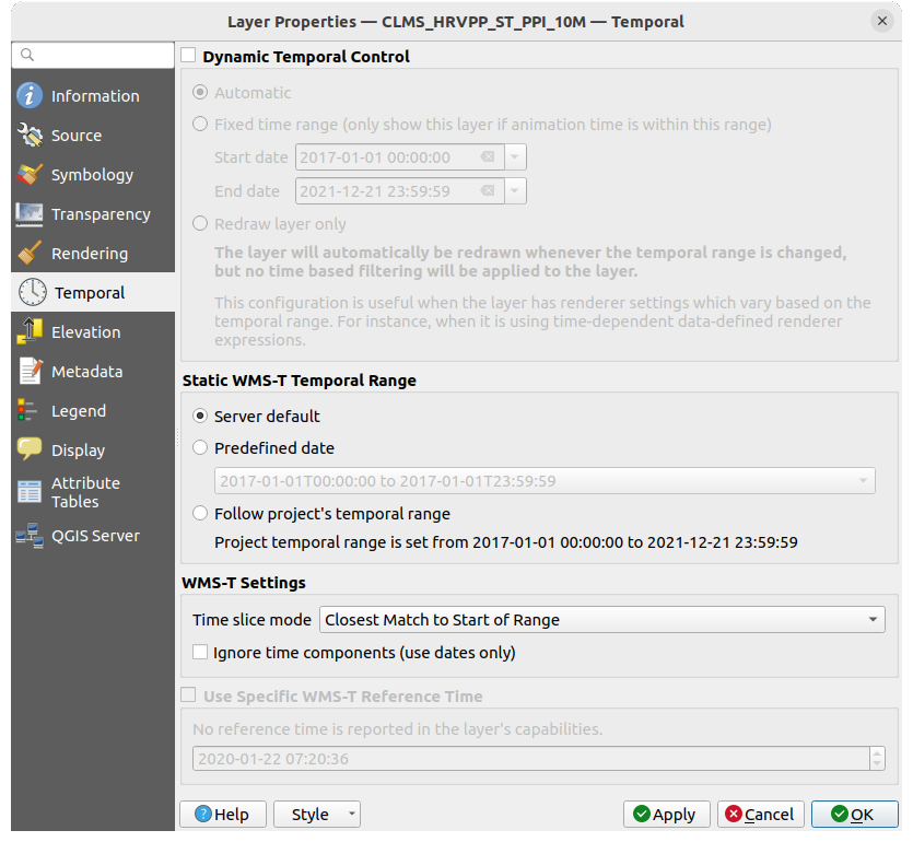
 A Web Coverage Service (WCS) provides access to raster data in forms that are useful
for client-side rendering, as input into scientific models, and for other clients.
The WCS may be compared to the WFS and the WMS. As WMS and WFS service instances, a
WCS allows clients to choose portions of a server’s information holdings based on
spatial constraints and other query criteria.
A Web Coverage Service (WCS) provides access to raster data in forms that are useful
for client-side rendering, as input into scientific models, and for other clients.
The WCS may be compared to the WFS and the WMS. As WMS and WFS service instances, a
WCS allows clients to choose portions of a server’s information holdings based on
spatial constraints and other query criteria. WCS tab
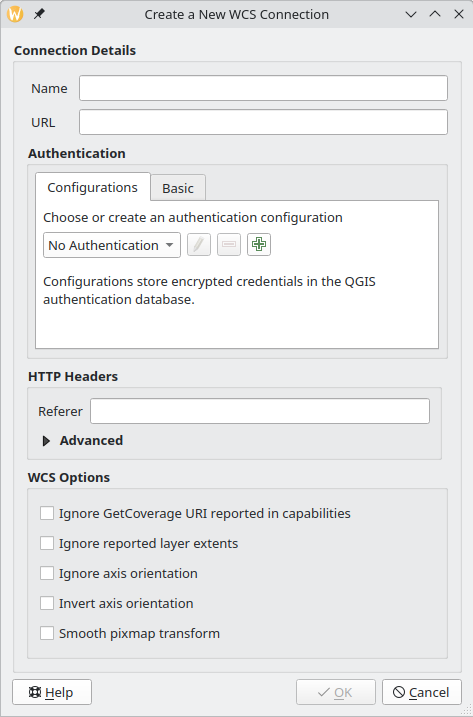
 WFS / OGC API - Features tab
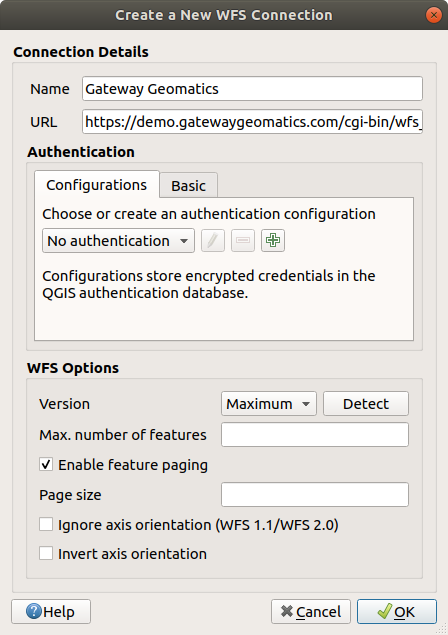
 icon next to it in the Layers panel.
It is thus possible to adjust the query at any moment.
icon next to it in the Layers panel.
It is thus possible to adjust the query at any moment.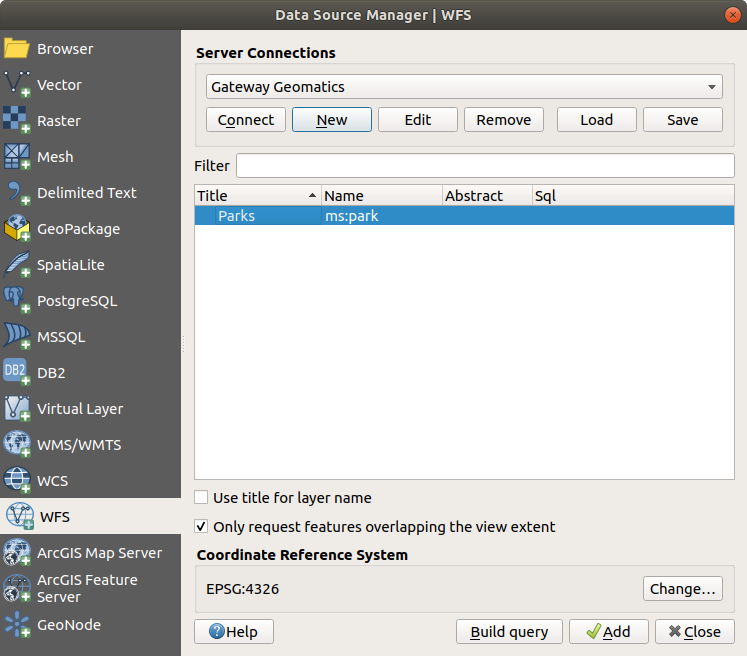
 SensorThings
tab in the Data Source Manager dialog.
SensorThings
tab in the Data Source Manager dialog.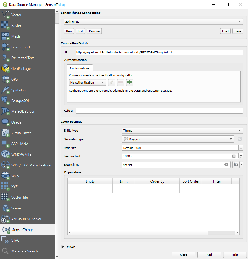
 Check available types to limit the list to the actually
supported geometry types.
Check available types to limit the list to the actually
supported geometry types.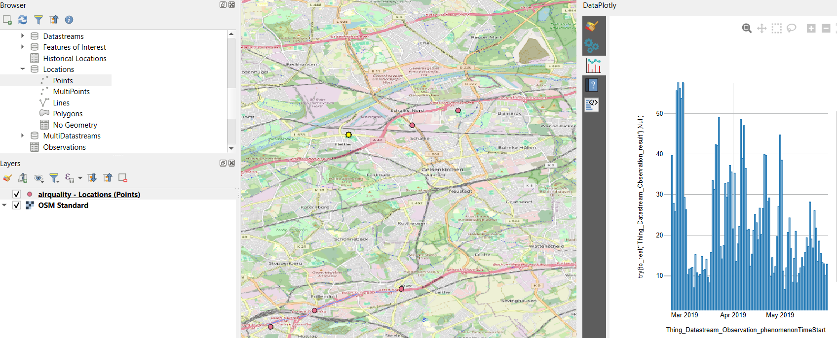
 STAC entry and select New STAC Connection….
In the dialog that appears, enter a Name for the connection, the URL of the STAC catalog
and optionally fill in Authentication credentials and a Referer.
Then click OK.
STAC entry and select New STAC Connection….
In the dialog that appears, enter a Name for the connection, the URL of the STAC catalog
and optionally fill in Authentication credentials and a Referer.
Then click OK.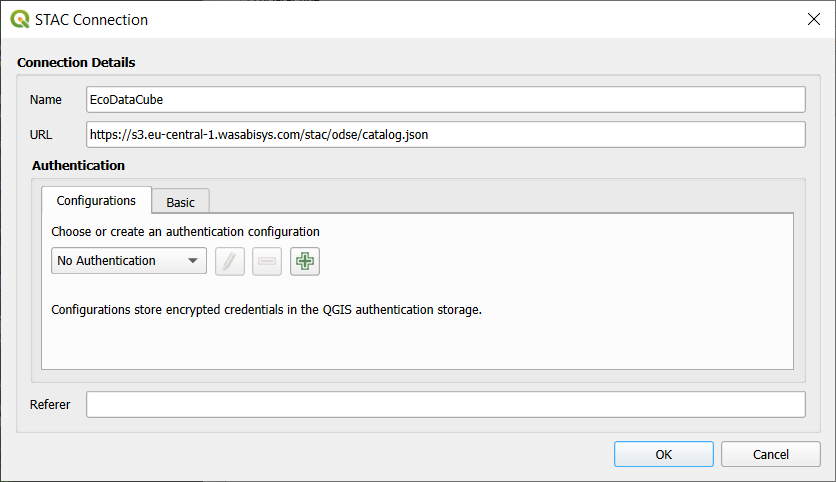
 Add Raster Layer…) to load and display the data.