9. QGIS anpassen
Sie können QGIS auf vielfache Art und Weise an Ihre Bedürfnisse anpassen. Im Menü finden Sie verschiedene Werkzeuge hierfür:
 Stilverwaltung…: erstellen und verwalten von Symbolen, Farbverläufen, etc.
 Benutzerprojektionen…: definieren Sie Ihre eigenen :ref:` Koordinatenbezugssystem<sec_custom_projections>`.
 Tastenkürzel…: legen Sie ihre eigenen <shortcuts> fest.
 Oberflächenanpassung…: passen Sie die Oberfäche an, indem Sie Dialoge oder Werkzeuge verstecken, die Sie für Ihre Arbeit nicht benötigen.
 Optionen…: hier können Sie verschiedene :ref:` <gui_options>` festlegen, die in unterschiedliche Bereiche gegliedert sind. Diese werden in den Einstellungen des aktuellen Benutzerprofils gespeichert und sind immer dann wirksam, wenn Sie mit diesem Profil arbeiten.
9.1. Optionen
Einige grundlegende Einstellungen für QGIS können Sie mit dem Dialog Optionen vornehmen. Wählen Sie im Menü aus. Hier können Sie die Einstellungen an Ihre Bedürfnisse anpassen. Einige Änderungen können einen Neustart von QGIS erfordern um wirksam zu werden.
Im Nachfolgenden werden die einzelnen Reiter beschrieben, in denen Sie die Optionen ihren Bedürfnissen anpassen können.
Bemerkung
Plugins können durch ihre eigenen Einstellungsmöglichkeiten die unten beschriebenen Optionen erweitern
Bitte beachten Sie, dass im Folgenden nur die Einstellungen der Kernanwendung beschrieben werden, wenn aber Erweiterungen installiert werden, ist es möglich, dass diese ihre eigenen Optionen in die Standarddialoge einfügen. Damit wird verhindert, dass jede Erweiterung einen eigenen Konfigurationsdialog mit eigenen Menüeinträgen mitbringt.
9.1.1. Allgemein
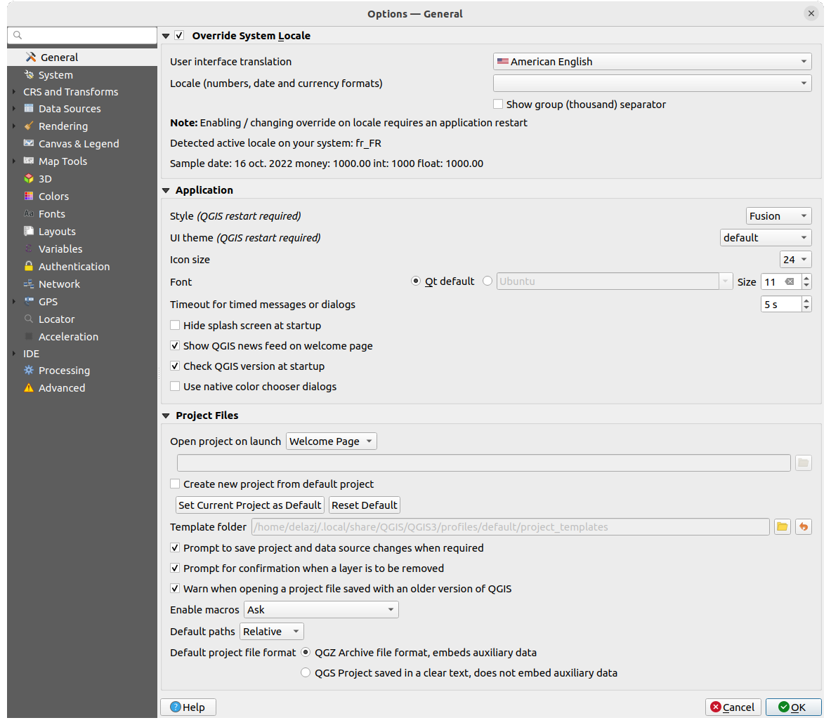
Abb. 9.1 Allgemein
System-Locale übersteuern
Standardmäßig verwendet QGIS die Konfiguration Ihres Betriebssystems für die Sprach- und Zahleinstellungen. Wenn Sie diese Gruppe aktivieren, können Sie dieses Verhalten anpassen:
Wählen Sie in Benutzeroberflächenübersetzung die Sprache aus, die für die Benutzeroberfläche verwendet werden soll
Wählen Sie in Locale (Zahlen-, Daten- Währungsformate) das System, in dem Datum und numerische Werte eingegeben und dargestellt werden sollen
 Gruppen-/Tausendertrennung anzeigen
Am unteren Rand des Bereichs wird eine Zusammenfassung der ausgewählten Einstellungen und deren Interpretation angezeigt.
Anwendung
Wählen Sie den Stil (QGIS-Neustart erforderlich), d.h. das Aussehen und die Anordnung der Elemente in Dialogen. Die Auswahlmöglichkeiten hängen von Ihrem Betriebssystem ab.
Legen Sie das Oberflächenthema (QGIS-Neustart erforderlich) fest
 . Mögliche Werte sind ‚default‘, ‚Night Mapping‘, und ‚Blend of Gray‘.
Legen Sie die Icon-Größe fest
Legen Sie die Schriftart und ihre Größe fest. Die Auswahl kann
 Qt Vorgabe oder eine benutzerdefinierte Schrift sein.
Ändern Sie die Dauer von zeitweiligen Meldungen und Dialogen
 Splashscreen beim Start nicht anzeigen
- QGIS-Neuigkeiten auf Willkommensseite anzeigen: zeigt einen QGIS-Newsfeed auf der Startseite an, der Sie über Projektneuigkeiten informiert (Datum und Zusammenfassung von Benutzer-/Entwicklertreffen, Community-Umfragen, Ankündigungen von Releases, verschiedene Tipps…)
mit
QGIS-Version beim Start überprüfen werden Sie informiert, wenn eine neue QGIS-Version veröffentlicht wurde- Native Farbauswahldialoge verwenden (siehe Farbauswahl)
Projektdateien
Projekt beim Start öffnen bietet die folgenden Möglichkeiten:
‚Willkommensseite‘ (Standardeinstellung): kann den „Newsfeed“ anzeigen, die Projektvorlagen und die zuletzt verwendeten Projekte des aktuellen Benutzerprofils (mit Vorschau); standardmäßig wird kein Projekt geöffnet
‚Neu‘: öffnet ein neues Projekt, das auf der Standardvorlage basiert
‚Zuletzt verwendetes‘: öffnet das zuletzt verwendete Projekt
‚Bestimmtes‘: öffnet ein festgelegtes Projekt; benutzen sie die … Schaltfläche, um das Projekt festzulegen
Unter
Neues Projekt aus Vorgabeprojekt erstellen können Sie das Aktuelle Projekt als Vorgabe speichern oder die Vorgabe zurücksetzen. In der Zeile darunter können Sie ein Verzeichnis festlegen, in dem Sie ihre benutzerdefinierten Projektvorlagen speichern. Diese werden dann dem Menü hinzugefügt.Wählen Sie
Bei Bedarf nachfragen, ob geänderte Projekte und Datenquellen gespeichert werden sollen, um zu verhindern, dass Ihre Änderungen verloren gehen.- Beim Löschen von Layern Bestätigung anfordern
- Warnung ausgeben, wenn QGIS-Projekt einer früheren Version geöffnet wird: Sie können Projekte, die mit einer älteren QGIS-Version gespeichert wurden, jederzeit öffnen; das Öffnen einer neueren Projektdatei mit einer älteren Version kann aber scheitern, weil neuere Entwicklungen in dieser Version noch nicht verfügbar sind.
Makros aktivieren
: diese Option stellt eine Sicherheitseinstellung dar und legt fest, wie das Ausführen von externen Makros gehandhabt wird; Sie können zwischen ‚Nie‘, ‚Fragen‘, ‚Nur in dieser Sitzung‘ und ‚Immer (nicht empfohlen)‘ wählen.Vorgabepfade: legt fest, ob Pfade zu Dateien und Layern, die in neuen Projekten verwendet werden, als ‚Absolut‘ oder ‚Relativ‘ zur Projektdatei gespeichert werden. Diese Einstellung kann auf Projektebene überschrieben werden.
Vorgabeprojektdateiformat
- QGZ-Archivdateiformat, enthält Zusatzdaten (siehe Hilfsspeicher)
 QGS-Projekt in Klartext speichern, unterstützt keine Zusatzdaten: die Zusatzdaten werden in einer separaten
 .qgd-Datei zusammen mit der Projektdatei gespeichert
9.1.2. System
SVG-Pfade
Es können Suchpfad(e) für SVG-Symbole (Scalable Vevtor Graphic) hinzugefügt oder entfernt werden. Alle SVG-Dateien, die sich in diesen Verzeichnissen befinden, stehen dann zur Verfügung, um die Objekte ihrer Karte zu symbolisieren, zu beschriften oder um Dekorationen hinzuzufügen (z.B. in der Layer-Symbolisierung oder der Stilverwaltung).
Lesen Sie auch das Kapitel Remote or embedded file selector für verschiedene Möglichkeiten, auf SVG-Dateien in einem QGIS-Pfad zu verweisen.
Erweiterungspfade
Fügen Sie Nach zusätzlichen C++-Erweiterungsbibliotheken zu durchsuchende Pfad(e) hinzu oder entfernen Sie diese.
Dokumentationspfade
Sie können Pfad(e) um nach QGIS-Hilfe zu suchen einfügen oder entfernen. Die eingetragenen Pfade werden von der QGIS-Hilfe benutzt. Als Voreinstellung finden Sie einen Link auf das offizielle QGIS-Onlinehandbuch, das der benutzen QGIS-Version entspricht. Sie können jedoch andere Links einfügen und sie in eine Reihenfolge von oben nach unten bringen: jedes mal, wenn Sie auf eine Schaltfläche Hilfe in einem Dialog klicken, wird der oberste Link geprüft; falls keine passende Seite gefunden wird, wird der nächste geprüft usw.
Bemerkung
Die Dokumentation wird nur für die QGIS Long Term Releases (LTR) versioniert und übersetzt. Das bedeutet, dass Sie, wenn Sie in einer regulären Version (z.B. QGIS 3.0) auf die Schaltfläche Hilfe klicken, als Voreinstellung das nächste LTR-Benutzerhandbuch angezeigt bekommen (d.h. 3.4 LTR), das aber Beschreibungen von Programmeigenschaften enthalten kann, die erst in neueren Versionen (3.2 und 3.4) enthalten sind. Falls keine LTR-Dokumentation verfügbar ist, wird die testing-Dokumentation angezeigt, die Programmeigenschaften von neueren und Entwicklerversionen enthält.
Einstellungen
Sie können die Benutzeroberflächeneinstellungen zurücksetzen (Neustart erforderlich) falls Sie eigene Anpassungen vorgenommen haben, diese aber wieder verwerfen wollen.
Umgebung
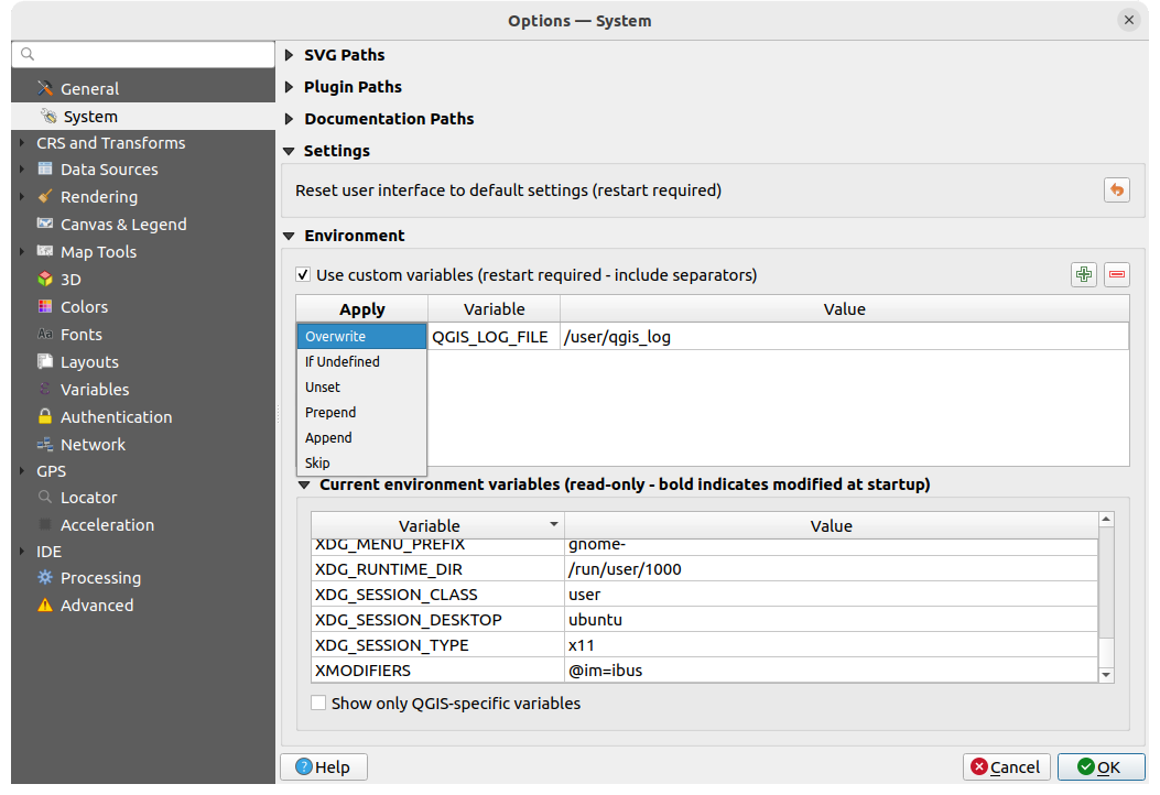
Abb. 9.2 Systemumgebungsvariablen
Die Systemumgebungsvariablen können in der Gruppe Umgebung eingesehen und viele davon auch konfiguriert werden. Dies ist nützlich für Plattformen wie Mac, wo eine GUI-Anwendung nicht unbedingt die Shell-Umgebung des Benutzers übernimmt. Es ist auch nützlich, um Umgebungsvariablen für die externen Werkzeuge, die von der Werkzegkiste gesteuert werden (z. B. SAGA, GRASS), anzuzeigen und zu setzen und um die Debugging-Ausgabe für bestimmte Abschnitte des Quellcodes zu aktivieren.
Wenn Sie das Kontrollkästchen Benutzerdefinierte Umgebungsvariablen verwenden (Neustart erforderlich - Trennzeichen einschließen) aktiviert haben, können Sie eine  neue Variable hinzufügen oder eine
  Variable entfernen. Für jedes neue Element können Sie einen Variable-Namen, einen Wert und die zu verwendende Anwenden-Methode konfigurieren, wobei die folgenden Methoden zur Verfügung stehen:
Überschreiben: ersetzt einen bereits existierenden Wert der Variablen
Wenn definiert: diesen Wert für die Variable verwenden, wenn er nicht bereits auf einer höheren Ebene definiert wurde (z. B. auf Betriebssystem- oder Anwendungsebene)
Nicht gesetzt: die Variable aus der Umgebung entfernen (der Parameter Wert wird nicht verwendet)
Voranstellen: den Wert dem bereits bestehenden Wert der Variablen voranstellen
Anhängen: den Wert dem bereits bestehenden Wert der Variablen anfügen
Überspringen: der Eintrag wird in der Liste für zukünftige Referenzzwecke aufbewahrt, aber nicht benutzt
Bereits definierte Umgebungsvariablen werden in Aktuelle Umgebungsvariablen angezeigt, wobei es möglich ist, sie durch Aktivierung der Checkbox Nur QGIS-spezifische Variablen anzeigen zu filtern.
9.1.3. KBS und Transformation
Bemerkung
Für weitere Informationen darüber, wie QGIS mit der Projektion von Layer umgeht, lesen Sie bitte den Abschnitt Arbeiten mit Projektionen.
9.1.3.1. KBS-Behandlung
Auf dem  KBS-Behandlung-Reiter können Sie festlegen, welches Koordinatenbezugssystem für ein neues Projekt oder einen neuen Layer verwendet werden soll.
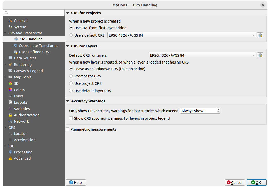
Abb. 9.3 KBS Einstellungen
KBS für Projekte
Um einem neu erzeugten Projekt ein KBS zuzuweisen, gibt es zwei Möglichkeiten:
- KBS des ersten hinzugefügten Layer verwenden: das KBS des Projekts wird auf das KBS des ersten geladenen Layers gesetzt
- Voreingestelltes KBS verwenden: Ein vorausgewähltes KBS wird standardmäßig auf jedes neue Projekt angewendet und bleibt beim Hinzufügen von Layern zum Projekt unverändert.
Die Auswahl wird für die Verwendung in späteren QGIS-Sitzungen gespeichert. Das Koordinatenbezugssystem des Projekts kann weiterhin über das Menü angepasst werden.
KBS für Layer
Vorgabe-KBS für Layer: hier können Sie ein Standard-KBS auswählen, das beim Erstellen eines Layers verwendet werden soll (wenn unten ausgewählt)
Sie können die Aktion festlegen, die ausgeführt werden soll, wenn ein neuer Layer erstellt wird oder wenn ein Layer ohne KBS geladen wird:
- Bei unbekanntem KBS belassen (nichts tun)
- KBS abfragen
- Projekt KBS verwenden
- Projekt KBS verwenden
Genauigkeitswarnungen
Nur KBS Genauigkeitswarnungen anzeigen, wenn Ungenauigkeiten größer sind als: hier kann eingestellt werden, wann eine Warnung angezeigt wird, wenn Sie einen Datensatz erstellen oder ändern und ein KBS auf der Grundlage eines Bezugssystems mit geringerer Genauigkeit auswählen. Die Voreinstellung ist Immer anzeigen, es kann aber auch ein Wert (in Metern) eingestellt werden. Benötigt eine QGIS Version mit mindestens PROJ 8.0.
KBS-Genauigkeitswarnung für Layer nur in Projektlegende anzeigen: Wenn diese Option aktiviert ist, wird jeder Layer mit einem KBS mit Genauigkeitsproblemen (d. h. ein dynamisches KBS, für das keine Koordinaten-Epoche verfügbar ist, oder ein KBS, das auf einem Bezugssystem mit einer inhärenten Ungenauigkeit basiert, die den vom Benutzer festgelegten Grenzwert überschreitet) im Layer Bedienfeld mit dem Warnsymbol  gekennzeichnet, das anzeigt, dass es sich um einen Layer mit geringer Genauigkeit handelt.
Dies wurde für den Einsatz in den Bereichen Ingenieurwesen, BIM, Asset Management und anderen Bereichen entwickelt, in denen Ungenauigkeiten dieser Art potenziell sehr gefährlich oder teuer sind!
Planimetric measurements: sets the default for the
planimetric measurements property for newly created projects.
9.1.3.2. Koordinatentransformationen
Auf dem  Koordinatentransformationen Reiter können Sie Koordinatentransformationen und Operationen festlegen, die beim Laden eines Layers in ein Projekt oder bei der Reprojektion eines Layers angewendet werden sollen.
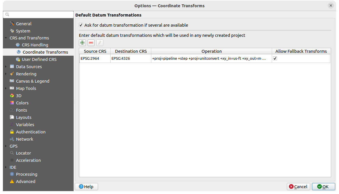
Abb. 9.4 Transformationseinstellungen
Datumstransformationsvorgabe
Hier können Sie einstellen, wie verfahren werden soll, wenn Layer in ein anderes KBS projiziert werden müssen:
automatisch die QGIS-Standardeinstellungen für Transformationen anwenden
oder Sie können individuelle Optionen einstellen:
- Datumstransformation erfragen, wenn mehrere verfügbar sind
aus einer vordefinierte Liste von Datumstransformationen eine bestimmte auswählen, die standardmäßig angewendet werden soll; für Details dazu siehe Datum Transformations
Sie können Vorgabedatumstransformationen hinzufügen, entfernen oder  bearbeiten, die für alle neu erzeugten Projekte verwendet werden sollen.
9.1.3.3. Benutzerdefinierte KBS
„“ .
Auf dem Reiter Benutzerdefinierte KBS können Sie Ihre eigenen KBS festlegen. Diese müssen dem WKT- oder Proj-Format entsprechen.
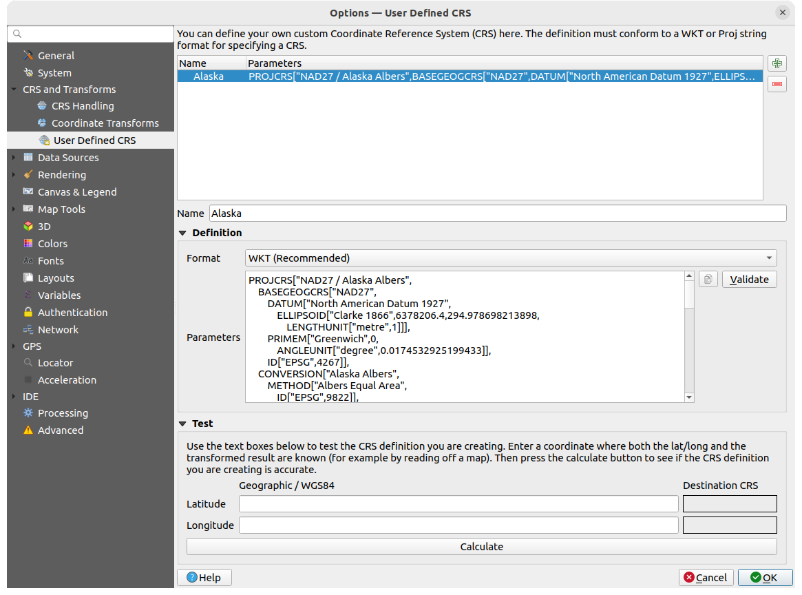
Abb. 9.5 Benutzerdefinierte KBS
Tragen Sie unter der Liste im Textfeld Name den gewünschten Namen ein und verwenden Sie die Neues KBS hinzufügen Schalfläche um ein neues KBS anzulegen. Wenn Sie ein vorhandenes KBS löschen möchten, können Sie die KBS entfernen Schlatfläche verwenden.
Definition
- Format
WKT (empfohlen)
Proj-Zeichenkette (Altlast - nicht empfohlen)
- Parameter
 Sie können die Parameter eines vorhandenem KBS kopieren
mit Validieren können Sie testen, ob Ihr Ausdruck korrekt ist
Test
Hier können Sie Ihre erstellte KBS-Definition anhand einer Umrechnung von Breiten- und Längengrad testen. Geben Sie eine bekannte Koordinate, um zu prüfen, ob die Umrechnung das korrekte Ergebnis liefert.
9.1.4. Datenquellen
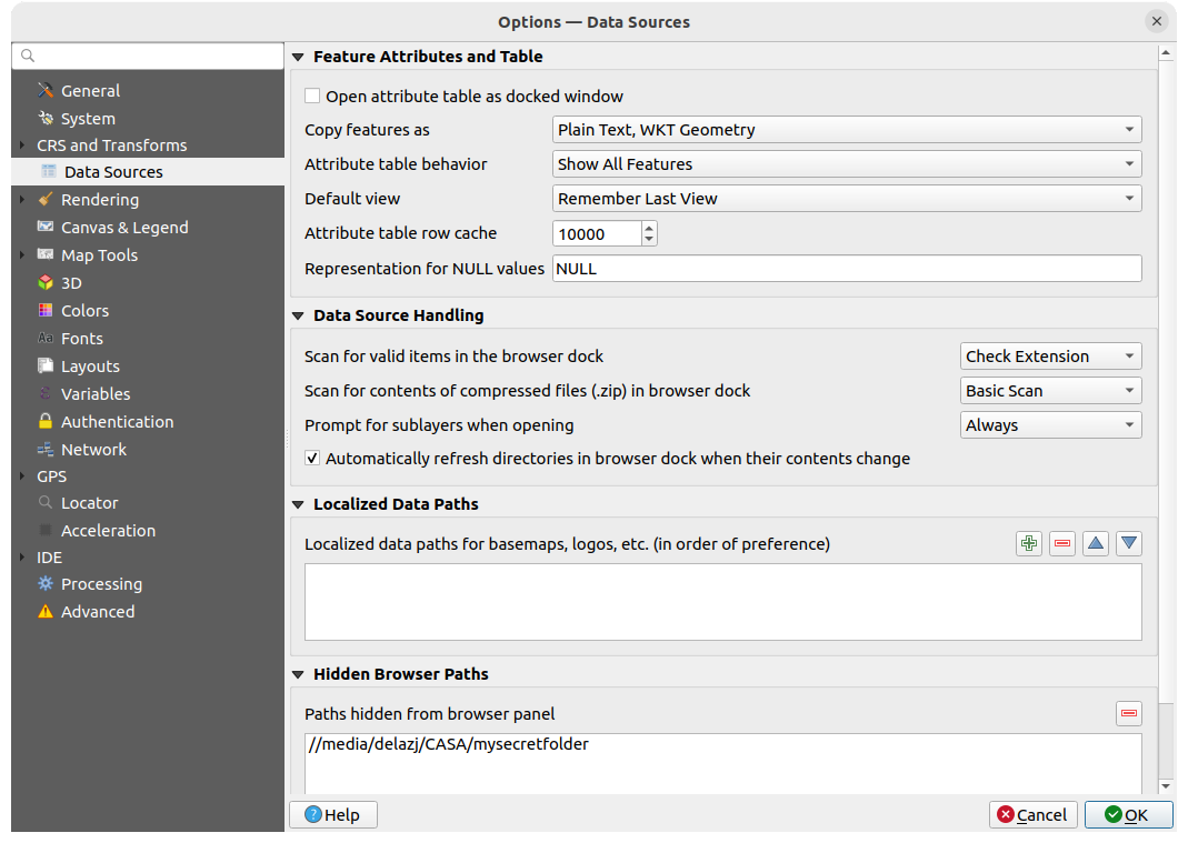
Abb. 9.6 Datenquellen
Objektattribute und -tabelle
- Attributtabelle im gedockten Fenster öffnen
Objekte kopieren als ‚Einfacher Text, WKT-Geometrie‘, ‚Einfacher Text, keine Geometrie‘, oder ‚GeoJSON‘ wenn Objekte in andere Anwendungen kopiert werden
Attributtabellenverhalten
: setzt beim Öffnen einen Filter auf die Attributtabelle; es gibt die folgenden Möglichkeiten: ‚Alle Objekte anzeigen‘, ‚Alle gewählten Objekte anzeigen‘ and ‚Sichtbare Objekte der Karte anzeigen‘.Voreingestellte Ansicht: definiert den Ansichtsmodus der Attributtabelle beim Öffnen; mögliche Einstellungen sind ‚Letzte Ansicht merken‘, ‚Tabellenansicht‘ oder ‚Formularansicht‘
Attributtabellenzeilencache
 : hier wird die Anzahl der Zeilen der zuletzte geladenen Tabelle festgelegt, die im Cache gespeichert werden; der Cache wird gelöscht, wenn die Attributtabelle geschlossen wird
Repräsentation für NULL-Werte. Hier können Sie einen Wert festlegen, der in Datenfeldern angezeigt wird, die einen NULL-Wert enthalten
Tipp
Schnelleres Öffnen von Attributtabellen mit sehr vielen Zeilen
Wenn Sie mit Layern mit einer großen Anzahl von Datensätzen arbeiten, kann das Öffnen der Attributtabelle lange dauern, da für die Anzeige alle Zeilen des Layers abfragt werden. Wenn Sie das Attributtabellenverhalten auf Sichtbare Objekte der Karte anzeigen setzen, wird QGIS beim Öffnen der Tabelle nur die Features in der aktuellen Kartenansicht abfragen, was ein schnelleres Laden der Daten ermöglicht.
Beachten Sie, dass bei dieser Einstellung die Attributtabelle immer nur Objekte enthält, die in der Kartenansicht sichtbar waren, als die Tabelle geöffnet wurde. Das bedeutet, dass auch nach dem Verschieben des Kartenausschnitts mit Alle Obkjekte anzeigen in der Tabelle keine neuen Objekte anzeigen werden. Sie können jedoch die angezeigten Objekte aktualisieren, indem Sie die Option Features auf der Karte sichtbar machen auswählen.
Datenquellenbehandlung
Nach gültigen Element im Browser suchen
. Sie können zwischen ‚Erweiterung prüfen‘ und ‚Dateiinhalt prüfen‘ wählen.Inhalt komprimierter Dateien (.zip) im Browser durchsuchen
legt fest, wie detailliert die Suche nach Informationen (für das Browser Bedienfeld) innerhalb solcher Dateien durchgeführt wird; die möglichen Einstellungen sind ‚Nein‘, ‚Grundsuche‘ and ‚Vollsuche‘.Beim Öffnen nach Unterlayern fragen. Einige Raster unterstützen Unterlayer, diese werden in GDAL auch „subdatasets“ genannt; ein Beispiel sind netCDF-Dateien. Mit dieser Option können Sie festlegen, wie mit Unterlayern verfahren werden soll, wenn eine Datei mit Unterlayern geöffnet wird. Sie haben die folgenden Auswahlmöglichkeiten:
‚Immer‘: Immer fragen (ob es Unterlayer gibt)
‚Wenn nötig‘: Fragen ob Layer keine Bänder aber Unterlayer hat
‚Nie‘: Nie fragen, lädt dann nichts
‚Alle laden‘: Nie auffordern aber alle Unterlayer laden
- Verzeichnisse im Browser-Dock automatisch aktualisieren, wenn sich der Inhalt ändert: Ermöglicht es Ihnen, die Überwachung von Verzeichnissen im Browser Bedienfeld zu deaktivieren (z. B. um eine mögliche Verlangsamung aufgrund von Netzwerklatenz zu vermeiden).
Lokalisierungsdatenpfade
Es ist möglich, lokalisierte Pfade für alle Arten von dateibasierten Datenquellen zu verwenden. Dabei handelt es sich um eine Liste von Pfaden, die zur Abstraktion des Speicherorts der Datenquelle verwendet werden. Wenn z. B. C:\my_maps in den lokalisierten Pfaden aufgeführt ist, wird ein Layer mit der Quelle C:\my_maps\my_country\ortho.tif im Projekt unter localized:my_country\ortho.tif gespeichert.
Die Pfade sind in der Reihenfolge ihrer Präferenz aufgelistet, d.h. QGIS sucht die Datei zuerst im ersten Pfad, dann im zweiten usw.
Ausgeblendeter Browserpfad
Hier werden alle Ordner aufgelistet, die Sie aus dem Browser Bedienfeld über das Kontextmenü ausgeblendet haben. Wenn Sie einen Ordner aus der Liste entfernen, wird er im Browser Bedienfeld wieder sichtbar.
9.1.4.1. GDAL
GDAL ist eine Bibliothek für den Datenaustausch von Geodaten, die eine große Anzahl von Vektor- und Rasterformaten unterstützt. Sie bietet Treiber zum Lesen und oft auch zum Schreiben von Daten in diesen Formaten. Der Reiter GDAL zeigt die Treiber für Raster- und Vektorformate und ihre Beschreibung an.
GDAL Raster- und Vektortreiber
Die Reiter Rastertreiber und Vektortreiber ermöglichen es Ihnen, festzulegen, welcher GDAL-Treiber zum Lesen und/oder Schreiben von Dateien verwendet werden soll, wenn mehr als ein GDAL-Treiber verfügbar ist.
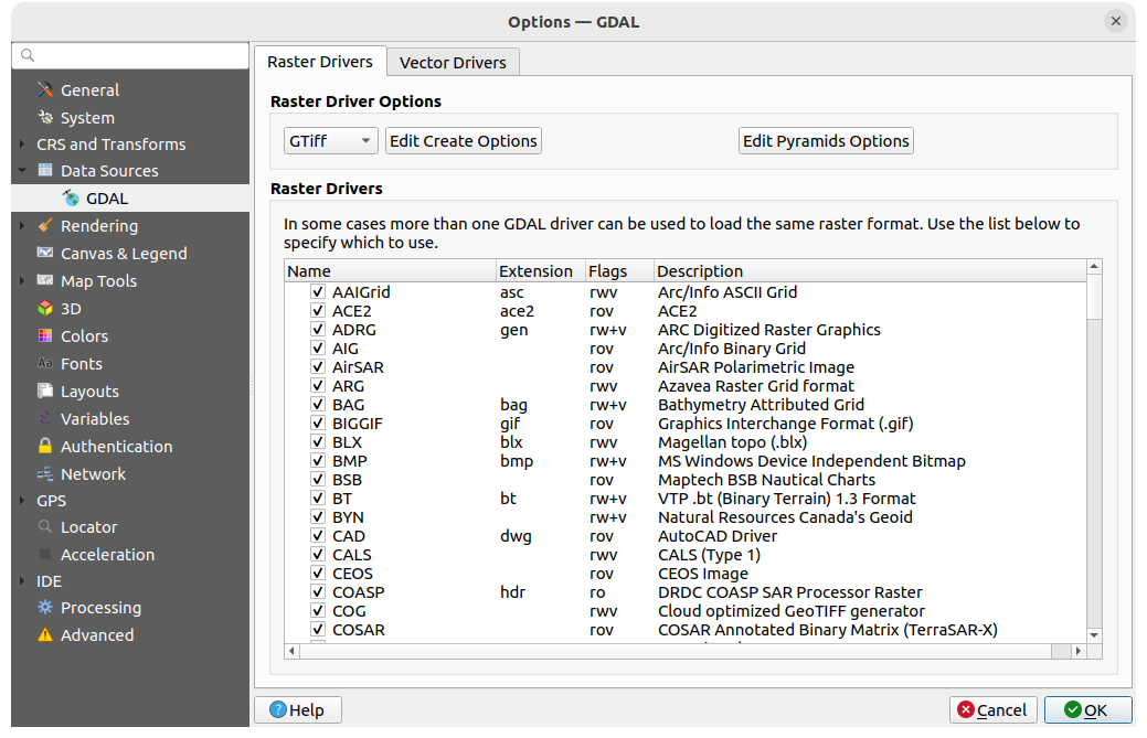
Abb. 9.7 GDAL - Rastertreiber
Tipp
Mit einem Doppelklick auf einen Rastertreiber für den Lese- und Schreibrechte bestehen (rw+(v)) öffnen Sie den Erzeugungsoptionen Dialog zur Anpassung.
Rastertreiberoptionen
Dieser Bereich bietet Möglichkeiten zur Anpassung des Verhaltens von Rastertreibern, auf die Lese- und Schreibzugriff besteht:
Erzeugungsoptionen bearbeiten: ermöglicht das Bearbeiten oder Hinzufügen verschiedener Profile für die Dateitransformation, d.h. eine Reihe vordefinierter Kombinationen von Parametern (Art und Grad der Komprimierung, Blockgröße, Übersicht, Farbmetrik, Alpha…), die bei der Ausgabe von Rasterdateien verwendet werden. Die verfügbaren Parameter hängen vom Treiber ab.
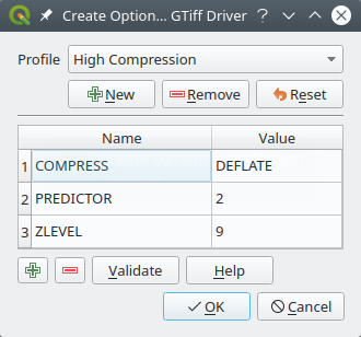
Abb. 9.8 Beispiel für die Erstellung eines Optionsprofils (für GeoTiff)
Im oberen Teil des Dialogfensters werden die aktuellen Profile aufgelistet, und Sie können neue Profile hinzufügen oder eines entfernen. Sie können das Profil auch auf seine Standardparameter zurücksetzen, wenn Sie diese geändert haben. Einige Treiber (z. B. GeoTiff) haben einige Beispielprofile, mit denen Sie arbeiten können.
Im unteren Bereich des Dialofensters finden Sie folgende Optionen:
Mit der
Schaltfläche können Sie neue Zeilen einfügen, in die Sie den Parameternamen und den Wert eintragenMit der
Schaltfläche können Sie den ausgewählten Parameter löschenMit der Prüfen Schaltfläche können Sie prüfen, ob die für das angegebene Format eingegebenen Erstellungsoptionen gültig sind
Benutzen Sie die Hilfe Schaltfläche, um die benötigen Parameter herauszufinden oder umd zur GDAL Rastertreiber Dokumentation zu gelangen.
Pyramiden-Optionen bearbeiten
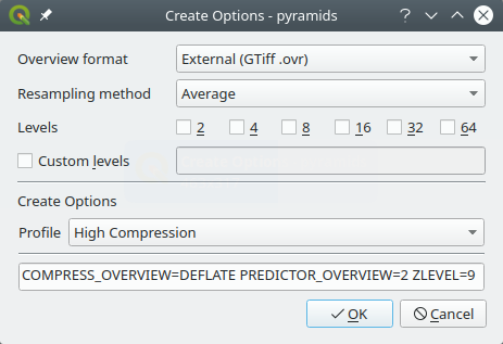
Abb. 9.9 Beispiel eines Pyramidenprofils
9.1.5. Darstellung
Der Reiter  Darstellung bietet Einstellungen zur Steuerung der Darstellung von Layern in der Kartenansicht.
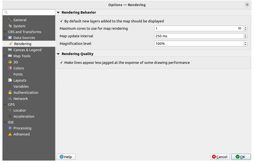
Abb. 9.10 Übersicht des Darstellungs-Reiters
Zeichenverhalten
- Normalerweise werden alle neuen Layer im Kartenfenster angezeigt: Die Deaktivierung dieser Option kann beim Laden mehrerer Layer nützlich sein, um zu vermeiden, dass jeder neue Layer in der Kartenansicht gerendert wird und so das Laden verlangsamt wird
Legen Sie die Anzahl der Maximal zu benutzenden Kerne fest
Die Kartenansicht wird im Hintergrund in einem separaten Image gerendert, und bei jedem Kartenaktualisierungsintervall (Standardwert 250 ms) wird der Inhalt dieses (nicht auf dem Bildschirm angezeigten) Images zur Aktualisierung der sichtbaren Kartenansicht verwendet. Wenn das Rendering der Kartenansicht jedoch schneller als diese Zeitspanne abgeschlossen ist, wird es sofort angezeigt.
Vergrößerungsgrad (siehe Abschnitt: <magnifier>)
Zeichenqualität
- Linie auf Kosten der Zeichengeschwindigkeit weniger gezackt zeichnen
9.1.5.1. Einstellungen zur Vektor-Darstellung
Der Reiter  Vektor enthält spezifische Einstellungen für die Darstellung von Vektor-Layern.
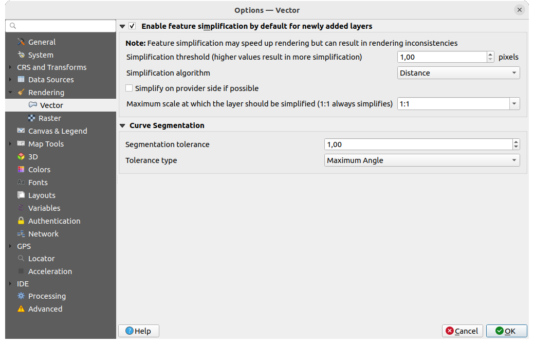
Abb. 9.11 Einstellungen zur Vektor-Darstellung
- Geometrievereinfachung für neue Layer voreinstellen: Sie können die Geometrie von Objekten in Vektorlayern vereinfachen (weniger Knoten), was zu einer schnelleren Darstellung führt. Beachten Sie jedoch, dass dies zu Inkonsistenzen bei der Darstellung führen kann. Verfügbare Einstellungen sind:
Vereinfachungsschwelle (höhere Werte führen zu stärkerer Vereinfachung)
Vereinfachungsalgorithmus: Diese Option führt eine „on-the-fly“ Vereinfachung von Objekten durch und beschleunigt so das Rendering der Geometrie. Die Geometrie der verwendeten Datenquellen wird dabei nicht verändert. Dies ist wichtig, wenn Sie Berechnungen haben, die die Geometrien der Objekte verwenden (z.B. die Fläche): es stellt sicher, dass diese Berechnungen auf der ursprünglichen Geometrie und nicht auf der vereinfachten Geometrie durchgeführt werden. Es stehen drei verschiedene Algorithmen hierfür zur Verfügung: ‚Entfernung‘ (Standard), ‚SnapToGrid‘ und ‚Visvalingam‘.
- Wenn möglich auf Anbieterseite vereinfachen: die Geometrien werden von der Datenquellenseite (PostGIS, Oracle…) vereinfacht. ACHTUNG: im Gegensatz zur lokalen Vereinfachung können die geometriebasierten Berechnungen davon betroffen sein!
Größter Maßstab bis zu dem der Layer vereinfacht werden soll (1:1 vereinfacht immer)
Bemerkung
Neben der globalen Einstellung kann die Vereinfachung von Objekten für jeden einzelnen Layer über eingestellt werden.
Kurvensegmentierung
Segmentierungstoleranz: Diese Einstellung steuert die Art und Weise, wie Kreisbögen gerendert werden. Je kleiner der maximale Winkel (zwischen den beiden aufeinanderfolgenden Scheitelpunkten und dem Kurvenzentrum in Grad) oder die maximale Differenz (Abstand zwischen dem Segment der beiden Scheitelpunkte und der Kurvenlinie in Karteneinheiten), desto mehr geradlinige Segmente werden beim Rendern verwendet.
Toleranztyp: kann Maximalwinkel oder Maximaldifferenz zwischen Annäherung und Kurve sein.
9.1.5.2. Raster Einstellungen
Der Reiter  Raster enthält spezifische Einstellungen für die Darstellung von Raster-Layern.
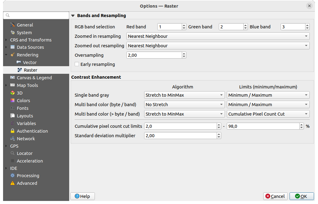
Abb. 9.12 Raster Einstellungen
Bereich Kanäle und Abtastung:
Mit RGB Kanalauswahl können Sie die Nummer für den Roten, Grünen und Blauen Kanal festlegen.
Bei der Abtastung für Hineinzoomen und der Abtastung für Hinauszoomen können verschiedene Methoden definiert werden; für Abtastung für Hineinzoomen können Sie zwischen drei Resampling-Methoden wählen: ‚Nächster Nachbar‘, ‚Bilinear‘ und ‚Kubisch‘. Für Abtastung für Hineinzoomen können Sie zwischen ‚Nächster Nachbar‘ und ‚Durchschnitt‘ wählen. Sie können auch einen Wert für die Überabtastung einstellen: zwischen 0,0 und 99,99 - ein großer Wert bedeutet mehr Arbeit für QGIS - der Standardwert ist 2.0.
- Frühe Abtastung: ermöglicht die Berechnung des Raster-Renderings auf der Seite des Datenanbieters (Datenquelle), wo die Auflösung der Quelle bekannt ist, und sorgt für ein besseres Zoomen beim Rendering mit QGIS benutzerdefiniertem Stil. Dies ist sehr praktisch für Vektor Tiles, die mit einer Interpretationsmethode geladen werden. Die Option kann auch auf Layer-Ebene gesetzt werden (Symbolisierung Eigenschaften).
Kontrastverbesserung kann für Einkanalgraustufen, Multikanalfarbe (Byte/Kanal) oder Multikanalfarbe (> Byte/Kanal) angewendet werden. Für jeden Punkt können Sie folgendes festlegen:
den zu verwendenden Algorithmus, welcher die Werte ‚Kein Strecken‘, ‚Strecken auf MinMax‘, ‚Auf MinMax strecken und zuschneiden‘ oder ‚Zuschneiden auf MinMax‘ haben kann
die Grenzen (Minimum/Maximum) festlegen, welche die Werte ‚Kumulativer Pixelanzahl-Schnitt‘, ‚Minimum/Maximum‘ oder ‚Mittlere +/- Standardabweichung‘ haben kann.
Die Kontrastverbesserung enthält darüber hinaus folgende Optionen:
Kommulative Pixelanzahl-Schnittgrenzen
Standardabweichungsfaktor
9.1.6. Karte & Legende
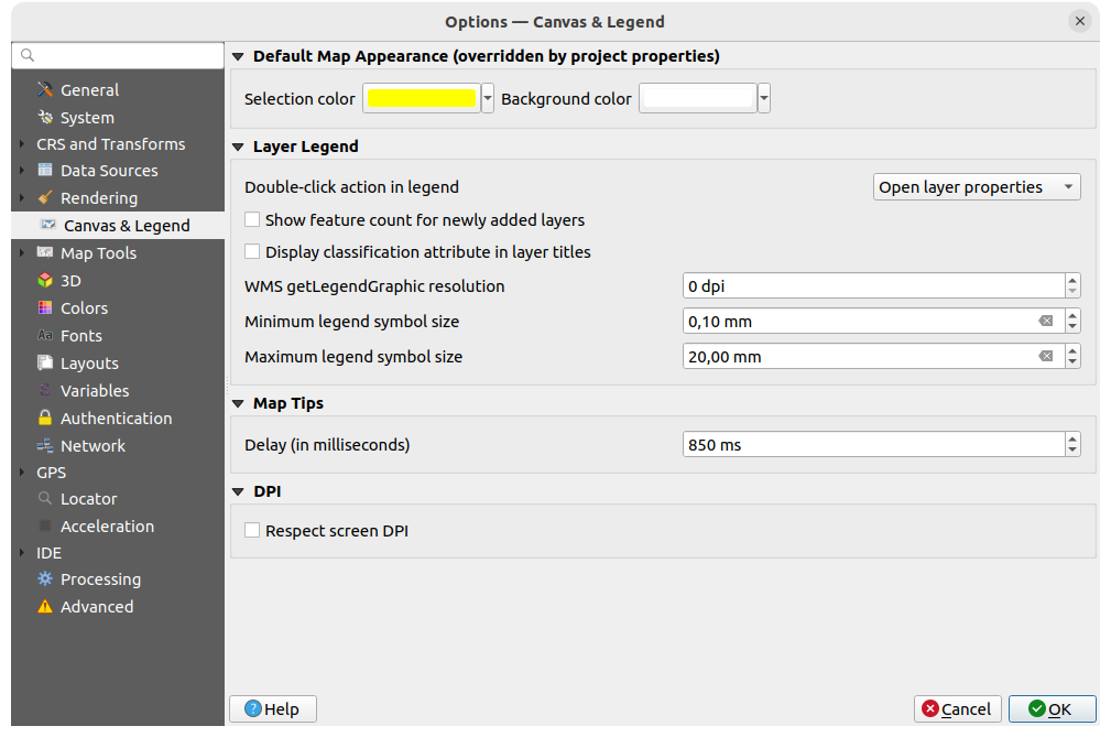
Abb. 9.13 Optionien auf dem Karte und Legende Reiter
Hier haben Sie die folgenden Einstellungsmöglichkeiten:
unter Voreingestelltes Kartenaussehen (Projekteigenschaften überschreiben): können Sie die Auswahlfarbe und die Hintergrundfarbe die verwendet werden sollen einstellen.
Anpassungsmöglichkeiten für die Layerlegende:
Für eine Doppelklick-Aktion in Legende
können sie zwichen den Optionen ‚Layereigenschaften öffnen‘, ‚Attributtabelle öffnen‘ und ‚Kartengestaltungsdock öffnen‘ wählen.- Objektanzahl für neu hinzugefügten Vektorlayer anzeigen: zeigt im Layer Bedienfeld die Anzahl der Objekte neben dem Layernamen an. Die Anzahl der Objekte in den Klassen, falls vorhanden, wird ebenfalls angezeigt. Sie können mit der rechten Maustaste auf einen Layer klicken, um die Anzahl der Objekte ein- oder auszuschalten.
- Klassifikationsattribute in Layertiteln anzeigen im „Layer“ Bedienfeld, z. B. bei der Anwendung einer kategorisierten oder regelbasierten Darstellung (s. Abschnitt Eigenschaften Symbolisierung für weitere Informationen).
die WMS-getLegendGraphic-Auflösung
mit Minimale Legendensymbolgröße und Maximale Legendensymbolgröße können Sie die Größe, mit der Symbole im ,:guilabel:Layer Bedienfeld angezeigt werden, einstellen
die Verzögerung (in Millisekunden) mit der Kartenhinweise eines Layers angezeigt werden
wenn
Bildschirmauflösung berücksichtigen: aktiviert ist, wird QGIS versuchen, die Kartenansicht mit physikalisch korrektem Verhältnis auf dem Bildschirm darzustellen, abhängig von der Auslösung des Monitors. Symbologien mit angegebenen Bildschirmgröße werden ebenfalls genau dargestellt, d.h. bei einer Einstellung von 10mm wird ein Symbol auch 10mm groß auf dem Bildschirm angezeigt. Die Schriftgrößen der Beschriftungen in der Kartenansicht können jedoch von denen in der QGIS Benutzeroberfläche oder anderen Anwendungen abweichen. Wenn diese Einstellung deaktiviert ist, verwendet QGIS die logische DPI des Betriebssystems, die mit anderen Anwendungen auf dem System übereinstimmt. Allerdings können die Kartenansicht und die Symbologiegröße auf dem Bildschirm ungenau sein. Insbesondere auf Bildschirmen mit hohen DPI-Werten erscheinen Symbologien wahrscheinlich zu klein.Es wird empfohlen, die Option
Bildschirmauflösung berücksichtigen zu aktivieren, insbesondere wenn Sie mehrere oder unterschiedliche Monitore verwenden und optisch hochwertige Karten erstellen wollen. Die Deaktivierung von Bildschirmauflösung berücksichtigen erzeugt eine Ausgabe, die möglicherweise besser für Karten geeignet ist, die nur für die Verwendung auf dem Bildschirm bestimmt sind, insbesondere wenn die Schriftgrößen anderen Anwendungen entsprechen sollen.
Bemerkung
Die Darstellung in Drucklayouts wird von der Einstellung Bildschirmauflösung berücksichtigen nicht beeinflusst; hier wird immer die angegebenen Auflösung verwendet. Beachten Sie auch, dass diese Einstellung die vom Betriebssystem gemeldete physische Bildschirm-Auflösung verwendet, der möglicherweise nicht bei allen Bildschirme korrekt ist.
9.1.7. Kartenwerkzeuge
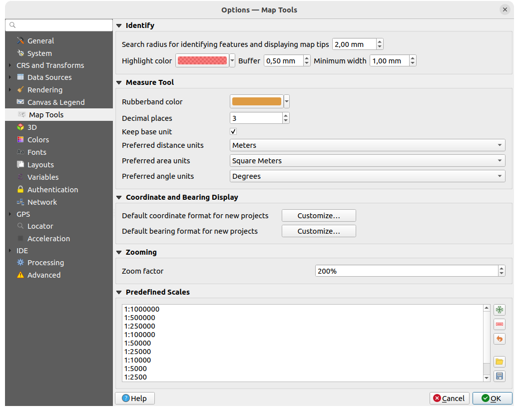
Abb. 9.14 Einstellungen Kartenwerkzeuge
Im obersten Bereich können einige Einstellungen im Bezug auf das Objekte abfragen-Werkzeug vorgenommen werden
Mit Suchradius für die Objektidentifikation und zur Anzeige von Kartenhinweisen kann der Abstand eingestellt werden, innerhalb dessen das Identifizierungswerkzeug Ergebnisse anzeigt
Mit der Hervorhebungsfarbe kann eingestellt werden, wie abgefragte Objekte angezeigt werden sollen
Puffer legt die Größe des Puffers fest, mit der die Hervorhebung dargestellt wird
Minimalbreite legt fest, wie dick die Umrisslinie eines hervorgehobenen Objektes sein soll
Messwerkzeug
Definieren Sie die Gummibandfarbe für das Messwerkzeug
Definieren Sie die Anzahl der Dezimalstellen, die beim Messen angezeigt werden
Wenn
Basiseinheit beibehalten aktiviert ist, werden große Zahlen nicht automatisch umgewandelt (z. B. Meter in Kilometer)Mit den folgdenden drei Dropdown-Menüs können Sie die Einheiten festlegen, die bevorzugt verwendet werden; die Optionen für die Bevorzugte Abstandseinheit sind: ‚Meter‘, ‚Kilometer‘, ‚Fuß‘, ‚Yard‘, ‚Meilen‘, ‚Seemeilen‘, ‚Zentimeter, ‚Millimeter‘, ‚Grad‘ und ‚Karteneinheiten‘
Die Optionen für die Bevorzugte Flächeneinheit sind: ‚Quadratmeter‘, ‚Quadratkilometer‘, ‚Quadratfuß‘, ‚Quadratyard‘, ‚Quadratmeilen‘, ‚Hektar‘, ‚Morgen‘, ‚Quadratseemeilen‘, ‚Quadratzentimeter‘, ‚Quadratmillimeter‘, ‚Quadratgrad‘ or ‚Karteneinheiten‘
Die Optionen für das Bevorzugte Winkelmaß sind: ‚Grad‘, ‚Bogenmaß‘, ‚Gon/Neugrad‘, ‚Bogenminuten‘, ‚Bogensekunden‘, ‚Umdrehungen‘, ‚Milliradianten (SI Definition)‘ und ‚Mil (NATO/militärische Definition)‘ or mil (NATO/military definition)
Koordinaten- und Kursanzeige
In diesem Bereich können Sie die folgenden Parameter Anpassen …:
Vorgabekoordinatenformat für neue Projekte, wie es im Koordinatenfeld in der QGIS-Statusleiste und im Bereich Koordinaten des
 Objekte abfragen Werkzeugs angezeigt wird
Kursformat für neue Projekte wie es in der Richtungsanzeige der Statusleiste und vom
 Kurs messen Werkzeug angezeigt wird
Diese Optionen können auf Projekt-Ebene überschrieben werden.
Zoomen
Legen Sie einen Zoomfaktor für Zoom-Werkzeuge und Mausrad fest.
Vordefinierte Maßstäbe
Hier finden Sie eine Liste vordefinierter Maßstäbe, die standardmäßig in den maßstabsbezogenen Dropdown-Menüs angezeigt werden (z. B. in der Maßstab Statusleiste, in der Auswahl der Sichtbarkeitsmaßstäbe oder in den Einstellungen für weitere 2D-Kartenansichten). Mit den Schaltflächen und können Sie Ihre eigenen Maßstäbe hinzufügen oder entfernen. Sie können die Liste auch in eine XML-Datei exportieren oder daraus importieren. Auf der rechten Seite steht eine Schaltfläche zur Verfügung, um die Liste wieder auf die Standardeinträge zurückzusetzen.
Im Dialogfeld der Projekteigenschaften können Sie auch eine eigene Liste von Maßstäben festlegen, die diese globale Liste in den Dropdown-Menüs überschreibt.
9.1.7.1. Digitalisieren
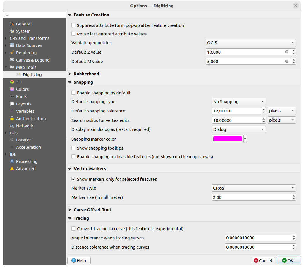
Abb. 9.15 Digitalisieren
Hier können Sie grundsätzlich Einstellungen für die Bearbeitung eines Vektorlayers festlegen (Geometrien und Attribute).
Objekterzeugung
- Attributeingabeformular bei der Objekterstellung unterdrücken; diese Auswahl kann aber für jeden Layer in den Layer-Eigenschaften überschrieben werden.
- Letzte Attributwerteingabe wiederverwenden: merkt sich den zuletzt verwendeten Wert eines jeden Attributs und verwendet ihn als Standard für das nächste digitalisierte Objekt (für jeden Layer separat). Dieses Verhalten kann auch für einzelne Felder gesteuert werden (see Einstellung der Feldfunktionsweisen).
Geometrien prüfen. Das Bearbeiten komplexer Linien/Polygone mit vielen Stützpunkten kann zu einer erheblichen Verlangsamung der Darstellung führen. Grund dafür ist das Standard-Validierungsverfahren, das viel Zeit benötigen. Um die Darstellung zu beschleunigen ist es möglich die Geometrieüberprüfung auszuschalten oder GEOS zu wählen. Die GEOS Geometrieüberprüfung ist deutlich schneller, hat aber den Nachteil, dass nur das erste Geometrieproblem gemeldet wird.
Beachten Sie, dass je nach Auswahl die Berichte über Geometriefehler unterschiedlich ausfallen können (see Types of error messages and their meanings)
Der Z-Vorgabewert wenn neue 3D Objekte erstellt werden kann hier festgelegt werden.
Gummiband
Hier können Sie die Linienstärke, Linienfarbe and die Füllfarbe festlegen.
Gummiband bei der Stützpunktbearbeitung nicht aktualisieren.
Einrasten
Mit
Einrasten voreinstellen legen Sie fest, dass die Einrastfunktion aktiviert ist, wenn ein Projekt geöffnet wirdSie können den Vorgabeeinrasttyp
festlegen; mögliche Optionen sind: (‚Stützpunkt‘, ‚Segment‘, ‚Fläche‘, ‚Zentroid‘, ‚Segmentmitte‘, ‚Linienendpunkt‘)Definieren Sie die Einrasttoleranzvorgabe in Karteneinheiten oder Pixeln
Definieren Sie den Suchradius für Stützpunktbearbeitung in Karteneinheiten oder Pixeln
Mit Hauptfenster anzeigen in (erfordert Neustart) können Sie festlegen ob das Einrasten-Fenster als ‚Dialog‘ oder als ‚Dock‘ angezeigt wird
Die Einrastmarkierfarbe kann ausgewählt werden
Wenn
Einrasthinweise anzeigen aktiviert ist, wird z.B. der Name des Layers angezeigt, an den gefangen wird. Das ist hilfreich, wenn mehrere Layer übereinander liegen.- Einrasten auf verborgene (nicht auf der Karte sichtbare) Objekte aktivieren
Stützpunktmarkierungen
- Markierungen nur für gewählte Objekte anzeigen
Legen Sie für die Stützpunktmarken den Markierungsstil
(‚Kreuz‘ (standard), ‚Teiltransparenter Kreis‘ oder ‚Keine‘) festDefinieren Sie die Markierungsgröße (in Millimeter)
**Werkzeug zum versetzen von Linien **
Die nächsten 3 Optionen beziehen sich auf das  Linie versetzen Werkzeug in Erweiterte Digitalisierung. Durch die verschiedenen Einstellungen ist es möglich die Form des Linienversatzes zu beeinflussen. Diese Optionen sind von GEOS 3.3 an möglich.
Der Verbindungsstil kann ‚Rund‘, ‚Eckig‘ oder ‚Abgefast‘ sein
Anzahl der Quadrantensegmente
Eckengrenze
Spurverfolgung
Wenn Spurverfolgung in Kurve umwandeln aktiviert ist, können Sie während der Digitalisierung automatisch Kurvensegemente erstellen. Bitte beachten Sie, dass es sich um eine experimentelle Funktion handelt und das der Datenanbieter, den Sie dazu verwenden, diese Funktion unterstützen muss.
9.1.8. 3D settings
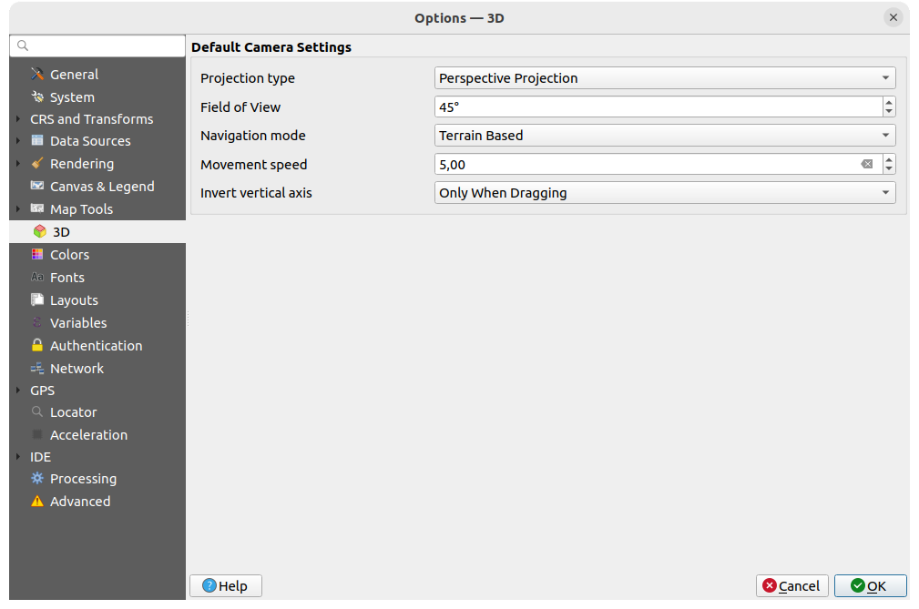
Abb. 9.16 3D settings
The  3D menu helps you configure some default settings to use
for any 3D Map view. These can refer to Default Camera Settings:
3D menu helps you configure some default settings to use
for any 3D Map view. These can refer to Default Camera Settings:
Projection type: allowing to view the 3D scene in a:
Perspective projection (default): Parallel lines appear to meet in the distance. Objects appear to shrink the farther they are from the camera.
or an Orthogonal projection: Parallel lines appear parallel. Objects appear the same size regardless of distance.
Camera’s Field of view: only relevant in perspective projection, specifies the current vertical field of view in degrees and determines how much of the scene is visible to the camera. Default value is 45°.
Navigation mode: provides different means to interact with the 3D scene. Available modes are:
Terrain based: the camera follows around a fixed position on the surface of the terrain as the scene is navigated.
Walk mode (first person)
Depending on the selected mode, navigation commands differ.
Movement speed
Invert vertical axis: Controls whether vertical axis movements should be inverted from their normal behaviour. Only affects movement in the Walk mode. It can be set to:
Never
Only when dragging: causes the vertical motion to inverted only when performing a click-and-drag camera rotation
and Always: causes the motions to be inverted when both click-and-dragging and when the camera movement is locked to the cursor (via a ~ key press)
9.1.9. Colors settings
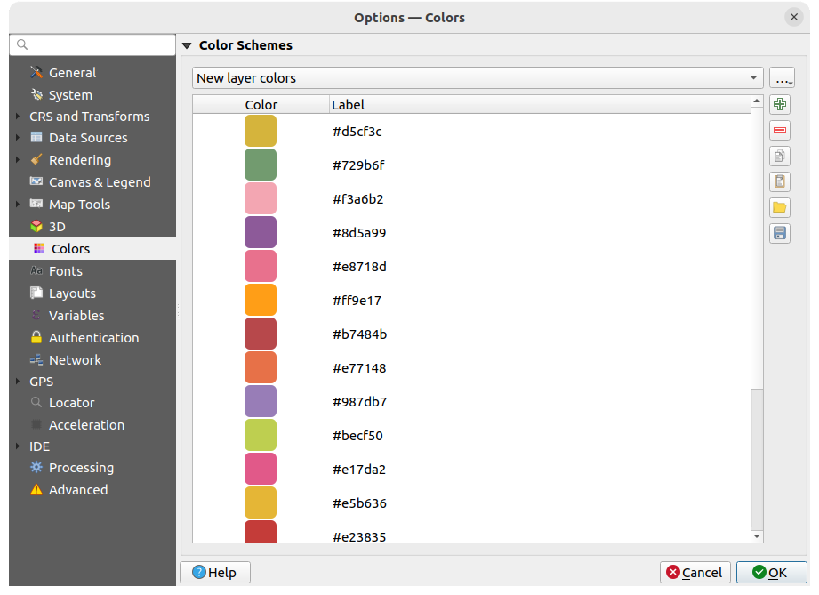
Abb. 9.17 Colors settings
This menu allows you to create or update palettes of colors used throughout the application in the color selector widget. You can choose from:
Recent colors showing recently used colors
Standard colors, the default palette of colors
Project colors, a set of colors specific to the current project (see Styles Properties for more details)
New layer colors, a set of colors to use by default when new layers are added to QGIS
or custom palette(s) you can create or import using the … button next to the palette combobox.
By default, Recent colors, Standard colors and Project colors palettes can not be removed and are set to appear in the color button drop-down. Custom palettes can also be added to this widget thanks to the Show in Color Buttons option.
For any of the palettes, you can manage the list of colors using the set of tools next to the frame, ie:
- Add or Remove color
- Copy or
 Paste color
  Import or
  Export the set of colors
from/to
Export the set of colors
from/to .gplfile.
Double-click a color in the list to tweak or replace it in the Color Selector dialog. You can also rename it by double-clicking in the Label column.
9.1.10. Fonts Settings
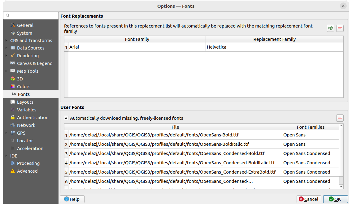
Abb. 9.18 Fonts settings
The Fonts tab provides support to manage fonts used across the projects:
Font Replacements: gives ability to populate a list of automatic font replacements to apply when loading projects or styles, allowing better support for projects and styles to be used across different operating systems (e.g. replace „Arial“ with „Helvetica“).
User Fonts: Allows you to place TTF or OTF fonts in the
fontssub-folder of the user profile. These fonts can be automatically loaded at QGIS startup time. This provides a way to use fonts without requiring them to be installed on an operating system level, which is often blocked in enterprise environments. The panel lists all installed user fonts and allows you to manage (i.e. remove) previously installed user fonts.It is also possible to
Automatically download missing, freely-licensed fonts:
E.g. if you open a project or style, or try to load a vector tile layer that references fonts that aren’t currently available,
then a hard-coded list of freely licensed fonts to download via URL is consulted to determine whether
it’s possible to automatically download the font to the user profile font directory (with notification of the font license).
9.1.11. Layouts settings
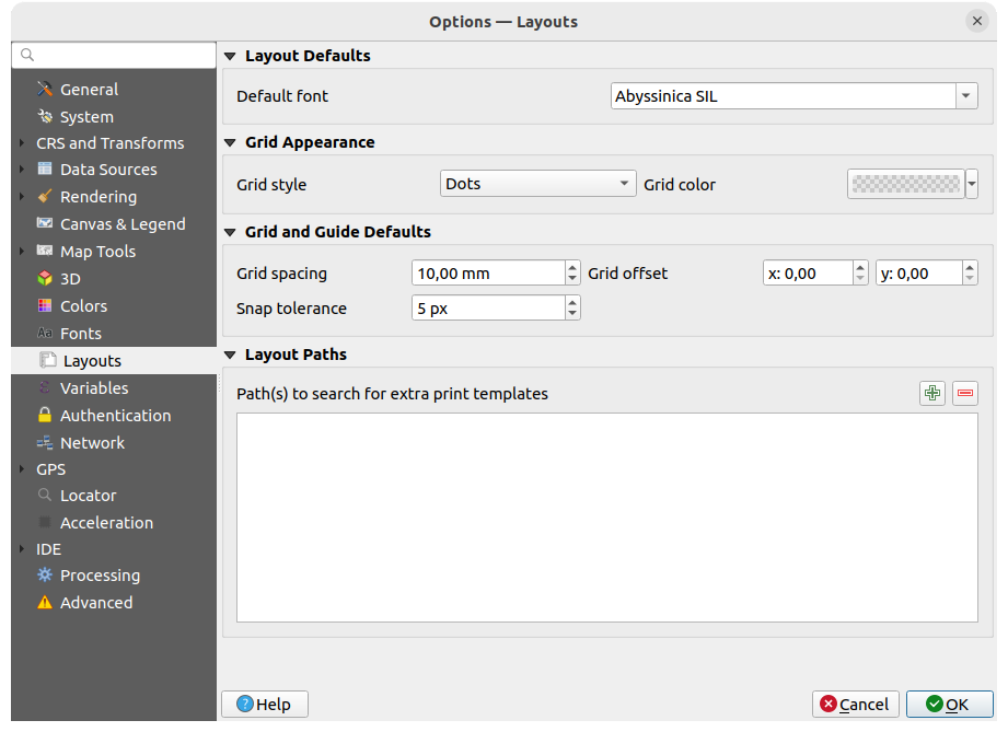
Abb. 9.19 Layouts settings
Zusammenstellungsvoreinstellungen
You can define the Default font used within the print layout.
Gitterdarstellung
Define the Grid style (‚Solid‘, ‚Dots‘, ‚Crosses‘)
Definieren Sie Gitterfarbe
Gitter- und Führungsvoreinstellungen
Define the Grid spacing
Define the Grid offset for X and Y
Define the Snap tolerance
Layout Paths
Define Path(s) to search for extra print templates: a list of folders with custom layout templates to use while creating new one.
9.1.12. Variables settings
The Variables tab lists all the variables available at the global-level.
It also allows the user to manage global-level variables. Click the
button to add a new custom global-level variable. Likewise, select a custom
global-level variable from the list and click the button to remove
it.
More information about variables in the Storing values in Variables section.
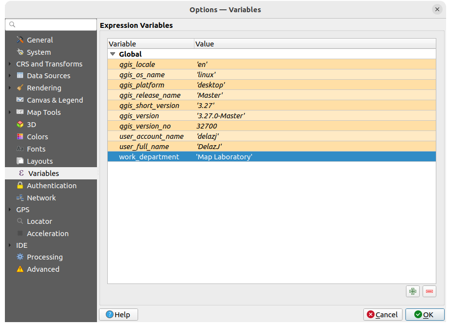
Abb. 9.20 Variables settings
9.1.13. Authentication settings
In dem Authentifikation Reiter können Sie Authentifikationskonfigurationen vornehmen und PKI Zertifikate verwalten. Für mehr Details siehe Authentifizierungssystem.
To manage authentications, you can use the list of tools next to the frame, ie:
- Add new authentication configuration
- Remove selected authentication configuration
 Edit selected authentication configuration
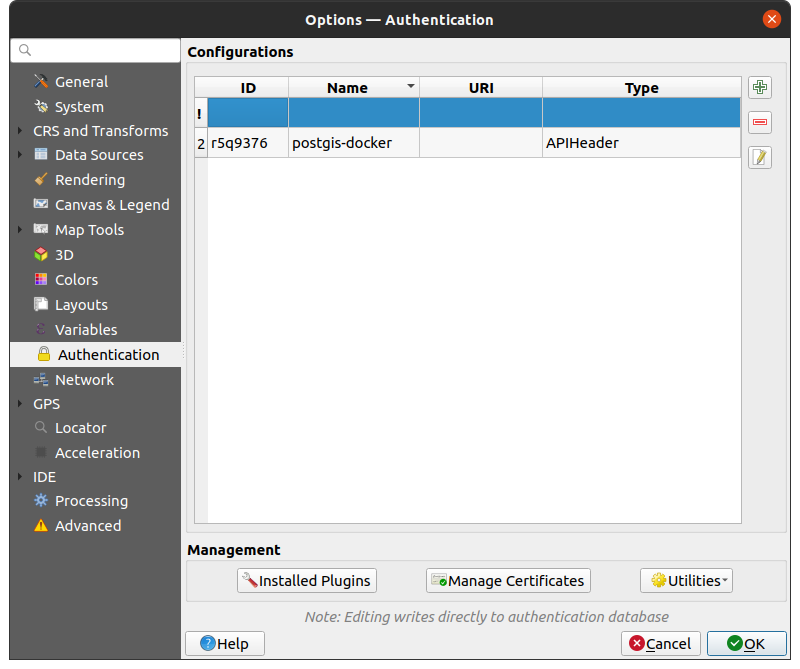
Abb. 9.21 Authentication settings
9.1.14. Network settings
Allgemein
Definieren Sie Zeitüberschreitung für Netzwerkanfragen (ms) - Standard ist 60000
Define Default expiration period for WMS Capabilities (hours) - default is 24
Define Default expiration period for WMS-C/WMTS tiles (hours) - default is 24
Define Max retry in case of tile or feature request errors
Definieren Sie User-Agent
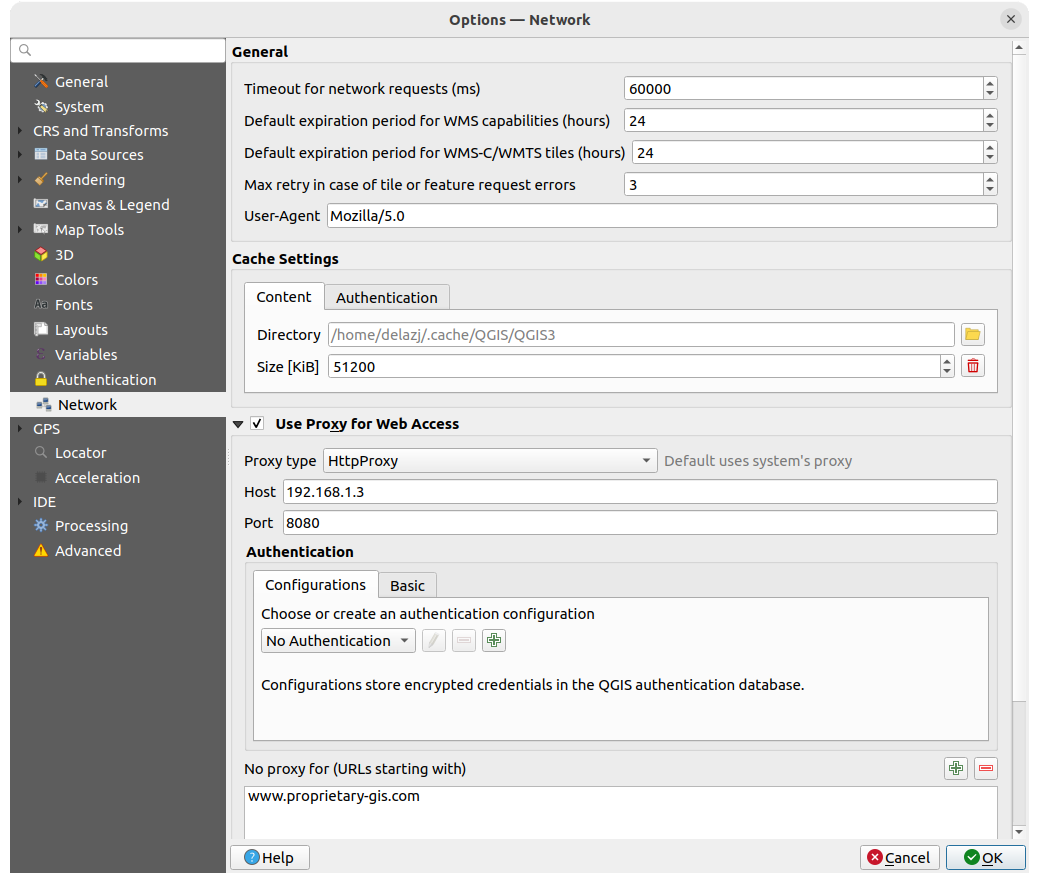
Abb. 9.22 Network and proxy settings
Cache-Einstellungen
Defines the Directory and a Size for the cache. Also offers tools to automatically clear the connection authentication cache on SSL errors (recommended).
Proxy for web access
- Use proxy for web access
Set the Proxy type
according to your needs and
define ‚Host‘ and ‚Port‘. Available proxy types are:: Proxy is determined based on system’s proxy
: Proxy für jede Art von Verbindung. Unterstützt TCP, UDP, Bindung an einen Port (eingehende Verbindungen) und Authentifizierung.
: Umgesetzt mit dem „CONNECT“-Befehl, unterstützt nur ausgehende TCP-Verbindungen und Authentifizierung.
:Umgesetzt mit normalen HTTP Befehlen ist dies nur im Zusammenhang mit HTTP Befehlen sinnvoll einzusetzen.
: Mit einem FTP-Proxy umgesetzt ist dies nur sinnvoll im Zusammenhang mit FTP-Anforderungen anzuwenden
Credentials of proxy are set using the authentication widget.
Excluding some URLs can be added to the text box below the proxy settings (see Abb. 9.22). No proxy will be used if the target url starts with one of the string listed in this text box.
If you need more detailed information about the different proxy settings, please refer to the manual of the underlying QT library documentation at https://doc.qt.io/archives/qt-5.9/qnetworkproxy.html#ProxyType-enum
Tipp
Proxy richtig anwenden
Using proxies can sometimes be tricky. It is useful to proceed by ‚trial and error‘ with the above proxy types, to check if they succeed in your case.
9.1.15. GPS settings
9.1.15.1. GPS Visualisation Options
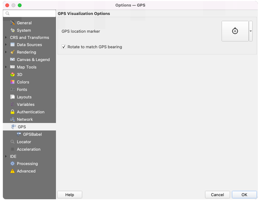
Abb. 9.23 GPS settings
This dialog helps you configure GPS devices display when connected to QGIS:
GPS location marker for controlling the marker symbol used for the current GPS location
Rotate to match GPS bearing: whether the marker symbol should be rotated to match the GPS direction
9.1.15.2. GPSBabel
GPSBabel converts waypoints, tracks, and routes between popular GPS receivers such as Garmin or Magellan and mapping programs like Google Earth or Basecamp. Literally hundreds of GPS receivers and programs are supported. QGIS relies on GPSBabel to interact with these devices and manipulate their data.
First you have to define the Path to GPSBabel binaries.
Then you may want to add your device. You can update devices list using
Add new device
or Remove device button.For each device:
you provide a Device name
you configure different Commands QGIS will use while interacting with it, such as:
Waypoint download from the device
Waypoint upload to the device
Route download from the device
Route upload to the device
Track download from the device
Track upload to the device
While the commands are usually GPSBabel commands, you can also use any other command line program that can create a GPX file. QGIS will replace the keywords
%type,%in, and%outwhen it runs the command.As an example, if you create a device type with the download command
gpsbabel %type -i garmin -o gpx %in %outand then use it to download waypoints from port/dev/ttyS0to the fileoutput.gpx, QGIS will replace the keywords and run the commandgpsbabel -w -i garmin -o gpx /dev/ttyS0 output.gpx.Read the GPSBabel manual for the command line options that may be specific to your use case.
Once you have created a new device type, it will appear in the device lists for the GPS download and upload algorithms.
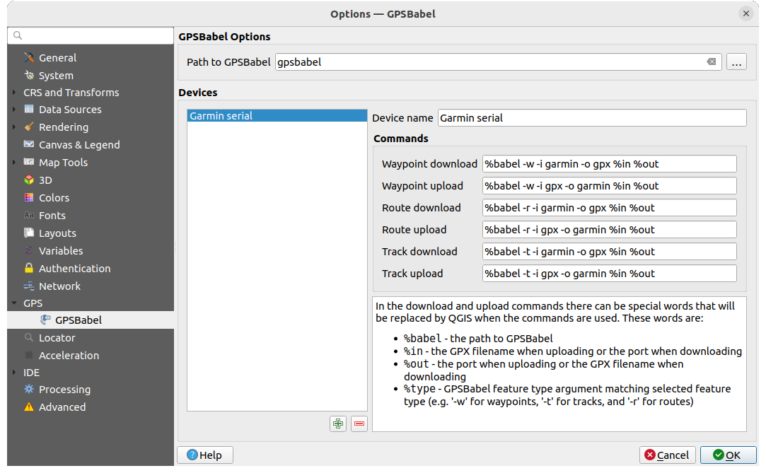
Abb. 9.24 GPS Babel settings
9.1.16. Locator settings
 The Locator tab lets you configure the Locator bar, a quick search widget available on the status bar to help
you perform searches in the application.
It provides some default filters (with prefix) to use:
The Locator tab lets you configure the Locator bar, a quick search widget available on the status bar to help
you perform searches in the application.
It provides some default filters (with prefix) to use:
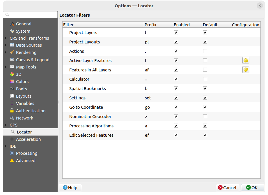
Abb. 9.25 Locator settings
Project Layers (
l): finds and selects a layer in the Layers panel.Project Layouts (
pl): finds and opens a print layout.Actions (
.): finds and executes a QGIS action; actions can be any tool or menu in QGIS, opening a panel…Active Layer Features (
f): searches for matching attributes in any field from the current active layer and zooms to the selected feature. Press to configure the maximum number of results.
Features in All Layers (
af): searches for matching attributes in the display name of each searchable layers and zooms to the selected feature. Press to configure the maximum number of results and the maximum
number of results per layer.Calculator (
=): allows evaluation of any QGIS expression and, if valid, gives an option to copy the result to the clipboard.Spatial Bookmarks (
b): finds and zooms to the bookmark extent.Settings (
set): browses and opens project and application-wide properties dialogs.Go to Coordinate (
go): pans the map canvas to a location defined by a comma or space separated pair of x and y coordinates or a formatted URL (e.g., OpenStreetMap, Leaflet, OpenLayer, Google Maps, …). The coordinate is expected in WGS 84 (epsg:4326) and/or map canvas CRS.Nominatim Geocoder (
>): geocodes using the Nominatim geocoding service of the OpenStreetMap Foundation.Processing Algorithms (
a): searches and opens a Processing algorithm dialog.Edit Selected Features (
ef): gives quick access and runs a compatible modify-in-place Processing algorithm on the active layer.
In the dialog, you can:
customize the filter Prefix, i.e. the keyword to use to trigger the filter
set whether the filter is Enabled: the filter can be used in the searches and a shortcut is available in the locator bar menu
set whether the filter is Default: a search not using a filter returns results from only the default filters categories.
Some filters provide a way to configure the number of results in a search.
The set of default locator filters can be extended by plugins, eg for OSM nominatim searches, direct database searching, layer catalog searches, …
9.1.17. Acceleration settings
OpenCL acceleration settings.
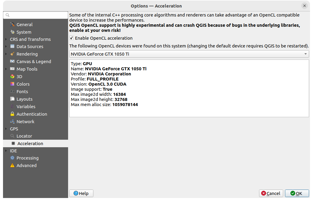
Abb. 9.26 Acceleration settings
Depending on your hardware and software, you may have to install additional libraries to enable OpenCL acceleration.
9.1.18. IDE settings
9.1.18.1. Code Editor settings
In the  Code Editor tab, you can control the appearance
and behaviour of code editor widgets (Python interactive console and editor,
expression widget and function editor, …).
Code Editor tab, you can control the appearance
and behaviour of code editor widgets (Python interactive console and editor,
expression widget and function editor, …).
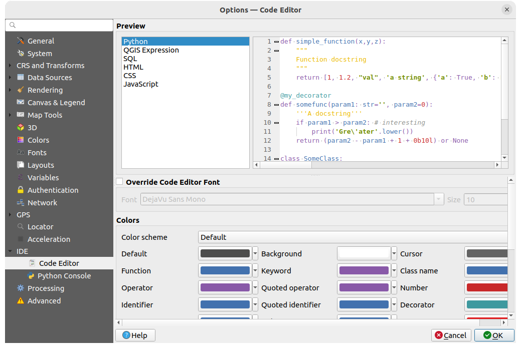
Abb. 9.27 Code Editor settings
At the top of the dialog, a widget provides a live preview of the current settings, in various coding languages (Python, QGIS expression, HTML, SQL, JavaScript). A convenient way to adjust settings.
Check
Override Code Editor Font to modify the default
Font family and Size.Under the Colors group, you can:
select a Color scheme: predefined settings are
Default,Solarized DarkandSolarized Light. ACustomscheme is triggered as soon as you modify a color and can be reset with selecting a predefined scheme.change the color of each element in code writing, such as the colors to use for comments, quotes, functions, background, …
9.1.18.2. Python Console settings
The  Python Console settings help you manage and control
the behavior of the Python editors (interactive console,
code editor, project macros,
custom expressions, …).
It can also be accessed using the Options… button from:
Python Console settings help you manage and control
the behavior of the Python editors (interactive console,
code editor, project macros,
custom expressions, …).
It can also be accessed using the Options… button from:
the Python console toolbar
the contextual menu of the Python console widget
and the contextual menu of the code editor.
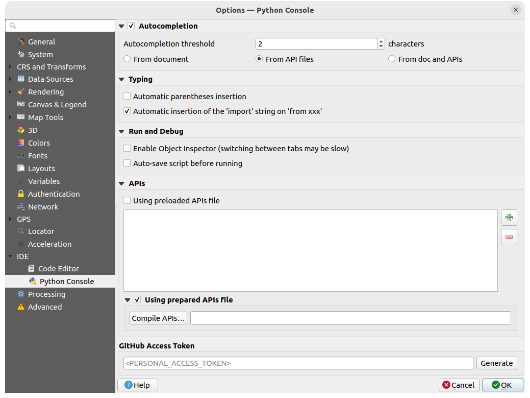
Abb. 9.28 Python Console settings
You can specify:
- Autocompletion: Enables code completion. You can get
autocompletion from the current document, the installed API files or both.
Autocompletion threshold: Sets the threshold for displaying the autocompletion list (in characters)
under Typing
- Automatic parentheses insertion: Enables autoclosing
for parentheses
- Automatic insertion of the ‚import‘ string on ‚from xxx‘:
Enables insertion of ‚import‘ when specifying imports
under Run and Debug
- Enable Object Inspector (switching between tabs may
be slow)
- Auto-save script before running: Saves the script
automatically when executed. This action will store a temporary file (in the
temporary system directory) that will be deleted automatically after running.
For APIs you can specify:
- Using preloaded APIs file: You can choose if you would
like to use the preloaded API files. If this is not checked you can add API
files and you can also choose if you would like to use prepared API files
(see next option).
- Using prepared APIs file: If checked, the chosen
*.papfile will be used for code completion. To generate a prepared API file you have to load at least one*.apifile and then compile it by clicking the Compile APIs… button.
Under GitHub access token, you can generate a personal token allowing you to share code snippets from within the Python code editor. More details on GitHub authentication
9.1.19. Processing settings
The  Processing tab provides you with general settings
of tools and data providers that are used in the QGIS Processing framework.
More information at QGIS Verarbeitung Umgebung.
Processing tab provides you with general settings
of tools and data providers that are used in the QGIS Processing framework.
More information at QGIS Verarbeitung Umgebung.
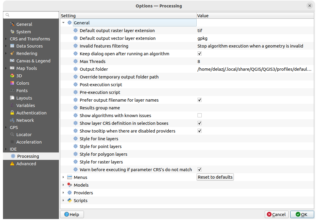
Abb. 9.29 Processing settings
9.1.20. Advanced settings
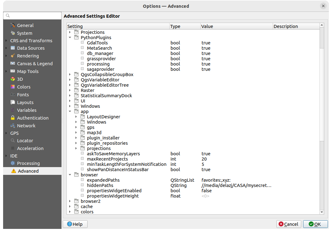
Abb. 9.30 Advanced settings
All the settings related to QGIS (UI, tools, data providers, Processing
configurations, default values and paths, plugins options, expressions,
geometry checks…) are saved in a QGIS/QGIS3.ini file under the active
user profile directory.
Configurations can be shared by copying this file to other installations.
From within QGIS, the Advanced tab offers a way to manage these
settings through the Advanced Settings Editor.
After you promise to be careful, the widget is populated with a tree of all
the existing settings, and you can edit their value.
Right-click over a setting or a group and you can delete it
(to add a setting or group, you have to edit the QGIS3.ini file).
Changes are automatically saved in the QGIS3.ini file.
Warnung
Avoid using the Advanced tab settings blindly
Be careful while modifying items in this dialog given that changes are automatically applied. Doing changes without knowledge can break your QGIS installation in various ways.
9.2. Working with User Profiles
The menu provides functions to set and access user profiles. A user profile is a unified application configuration that allows to store in a single folder:
all the global settings, including locale, projections, authentication settings, color palettes, shortcuts…
GUI configurations and customization
grid files and other proj helper files installed for datum transformation
installed plugins and their configurations
project templates and history of saved project with their image preview
processing settings, logs, scripts, models.
By default, a QGIS installation contains a single user profile named default.
But you can create as many user profiles as you want:
Click the New profile… entry.
You’ll be prompted to provide a profile name, creating a folder of the same name under
~/<UserProfiles>/where:~represents the HOME directory, which on Windows is usually
something like
Windows is usually
something like C:\Users\<username>.and
<UserProfiles>represents the main profiles folder, i.e.:
.local/share/QGIS/QGIS3/profiles/-
%AppData%\Roaming\QGIS\QGIS3\profiles\ 
Library/Application Support/QGIS/QGIS3/profiles/
The user profile folder can be opened from within QGIS using the Open Active Profile Folder.
A new instance of QGIS is started, using a clean configuration. You can then set your custom configurations.
If you have more than one profile in your QGIS installation, the name of the active profile is shown in the application title bar between square brackets.
As each user profile contains isolated settings, plugins and history they can be great for different workflows, demos, users of the same machine, or testing settings, etc. And you can switch from one to the other by selecting them in the menu. You can also run QGIS with a specific user profile from the command line.
Unless changed, the profile of the last closed QGIS session will be used in the following QGIS sessions.
Tipp
Run QGIS under a new user profile to check for bug persistence
When you encounter weird behavior with some functions in QGIS, create a new user profile and run the commands again. Sometimes, bugs are related to some leftovers in the current user profile and creating a new one may fix them as it restarts QGIS with the new (clean) profile.
9.3. Projekteigenschaften
In the properties window for the project under , you can set project-specific options. The project-specific options overwrite their equivalent in the Options dialog described above.
9.3.1. General Properties
In the  General tab, the General settings let you:
see the location of the project file
set the folder for the project home (available in the Project home item of the Browser panel). The path can be relative to the folder of the project file (type it in) or absolute. The project home can be used for storing data and other content that is useful for the project. Convenient when dataset and project files are not stored at the same place. If not filled, the Project home defaults to the project file folder.
einen Titel für das Projekt hinter dem Projektpfad vergeben
die Farbe auswählen, die markierte Objekte haben, wenn sie ausgewählt sind
die Hintergrundfarbe wählen: die Farbe für den Kartenhintergrund
einstellen, ob der Pfad zu den Layern des Projekts als absolute (voll) oder als relative zu der Projektdatei gespeichert werden soll. Sie bevorzugen wahrscheinlich relative Pfade, wenn Layer und Projektdatei bewegt werden oder geteilt oder wenn Sie von Computern auf verschiedenen Plattformen auf das Projekt zugreifen wollen.
wählen Sie Artefakte bei der Darstellung von Kartenkacheln vermeiden. Beachten Sie, dass diese Option zu Leistungseinbußen führen kann.
Remember attribute tables windows and docks between sessions: If checked for a project, then any opened attribute tables will be saved into the project and immediately restored when loading that project. This can improve workflows when you constructed a project with a particular set of attribute table configurations for your requirements, and re-setting up these attribute tables is a hassle.
Calculating areas and distances is a common need in GIS. However, these values are really tied to the underlying projection settings. The Measurements frame lets you control these parameters. You can indeed choose:
the Ellipsoid, on which distance and area calculations are entirely based; it can be:
None/Planimetric: returned values are in this case cartesian measurements. This option can be set as default for new projects from the
menua Custom one: you’ll need to set values of the semi-major and semi-minor axes.
or an existing one from a predefined list (Clarke 1866, Clarke 1880 IGN, New International 1967, WGS 84…).
Die Einheiten für Entfernungsmessung für Länge und Umfang und die Einheiten für Flächenmessung. Diese Einstellungen, die standardmäßig über die festgelegten Einheiten in den QGIS Optionen definiert sind, werden dann aber überschrieben für das aktuelle Projekt, werden eingesetzt in:
Attributtabellen Feld mit Aktualisierungsleiste
Feldrechner Berechnungen
Abfragewerkzeug abgeleitet von Länge, Umfang und Flächenwerten
Standardeinheiten gezeigt im Messen Dialog
The Coordinate and Bearing display allows you to customize the display of:
the coordinates shown in the Coordinates box on QGIS status bar and in the Derived section of the
Identify
features tool’s resultsthe bearing value displayed in the status bar for the map canvas panning direction and by the
Measure bearing tool.
Available parameters are:
Display coordinates using either:
Map Units, based on the project CRSMap Geographic (degrees): based on the project CRS if it is of geographic type, otherwise uses its associated geographic CRS. This is helpful e.g. for non-earth celestial bodies.or
Custom Projection Units: allows to rely on any CRS you desire for coordinates display
In the Coordinate CRS option, you can view or define the CRS to use depending on your display mode.
Coordinate format: you can configure it as
Decimal Degrees,Degrees, MinutesorDegrees, Minutes, Seconds, and whether it should display:- Show directional suffix
- Show leading zeros for minutes and seconds
- Show leading zeros for degrees
- Show trailing zeros
Coordinate precision: the number of decimal places can be automatic (derived from the type of CRS) or set manually
Coordinate order: you can opt to display the coordinates in the native order of the CRS (
Default) or switch it to eitherEasting, Northing (Longitude, Latitude)orNorthing, Easting (Latitude, Longitude)orderBearing format possible values are
0 to 180°, with E/W suffix,-180 to +180°or0 to 360°. The number of Decimal places as well as whether to Show trailing zeros can be set.
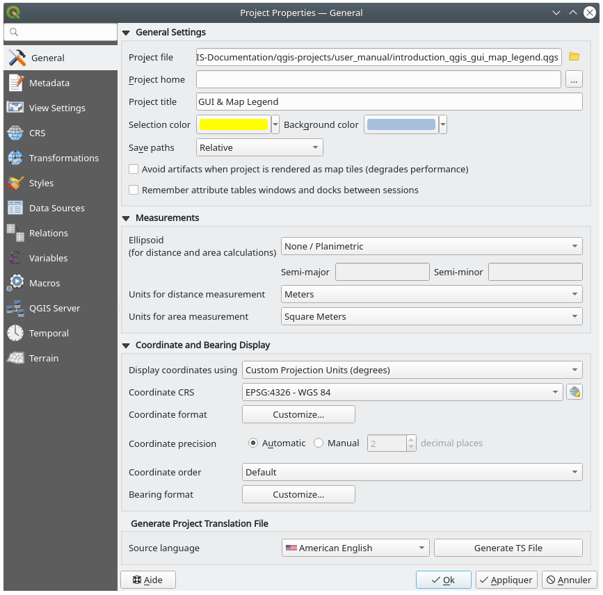
Abb. 9.31 General tab of the Project Properties dialog
9.3.2. Eigenschaften Metadaten
The  Metadata tab allows detailed metadata to be defined,
including (among the others): author, creation date, language, abstracts,
categories, keywords, contact details, links, history. There is also a
validation functionality that checks if specific fields were filled, anyway
this is not enforced. See vector layer metadata properties for some details.
Metadata tab allows detailed metadata to be defined,
including (among the others): author, creation date, language, abstracts,
categories, keywords, contact details, links, history. There is also a
validation functionality that checks if specific fields were filled, anyway
this is not enforced. See vector layer metadata properties for some details.
9.3.3. View Settings
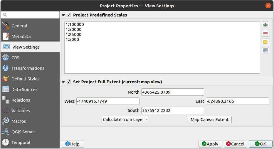
Abb. 9.32 View Settings tab of the Project Properties dialog
The  View Settings tab provides means to control
the project map canvas. You can:
View Settings tab provides means to control
the project map canvas. You can:
set Project predefined scales: the list of scales to display in scale-related drop-down widgets, such as the status bar Scale, the visibility scales selector or secondary 2D map view settings,… in replacement of the global predefined scales.
Set Project full Extent: this extent will be used instead of the extent of all layers when zooming to full map extent (
 ).
It’s useful when a project contains web layers/national layers/global layers
yet the actual area of interest for the project is a smaller geographic area.
The project full extent coordinates can be set with the extent selector widget.
).
It’s useful when a project contains web layers/national layers/global layers
yet the actual area of interest for the project is a smaller geographic area.
The project full extent coordinates can be set with the extent selector widget.
9.3.4. CRS Properties
Bemerkung
For more information on how QGIS handles project projection, please read the dedicated section at Arbeiten mit Projektionen.
The CRS tab helps you set the coordinate reference system
to use in this project. It can be:
- No CRS (or unknown/non-Earth projection):
layers are drawn based on their raw coordinates
or an existing coordinate reference system that can be geographic, projected or user-defined. Layers added to the project are translated on-the-fly to this CRS in order to overlay them regardless their original CRS.
9.3.5. Transformations Properties
The Transformations tab helps you control the
layers reprojection settings by configuring the datum transformation preferences
to apply in the current project. As usual, these override any corresponding
global settings. See Datum Transformations for more details.
9.3.6. Styles Properties
Under  Styles tab, you can configure symbols and colors
inherent to the project, allowing to safely share the project among different
machines.
Styles tab, you can configure symbols and colors
inherent to the project, allowing to safely share the project among different
machines.
The Default Symbols group lets you control how new layers will
be drawn in the project when they do not have an existing .qml style
defined. You can set Marker, Line, Fill to
apply depending on the layer geometry type as well as default Color
Ramp and Text Format (e.g. when enabling labeling).
Any of these items can be reset using the Clear entry from
the corresponding drop-down widget.
In the Options group, you can:
Apply a default Opacity to new layers
- Assign random colors to symbols, modifying the symbols
fill colors, hence avoiding same rendering for all layers.
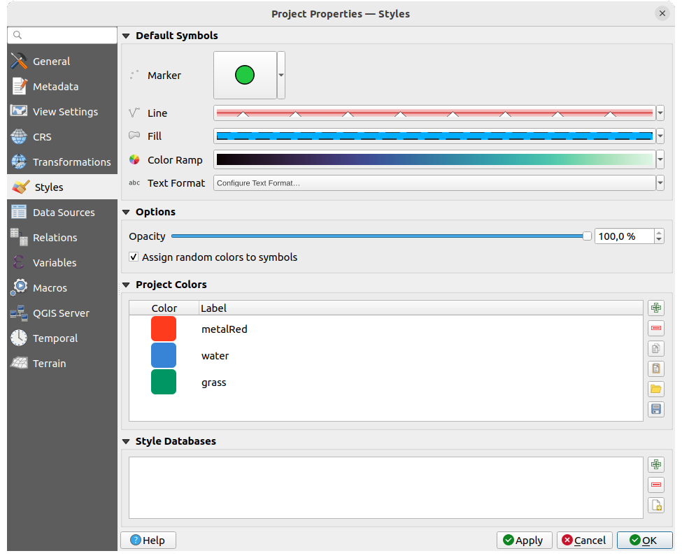
Abb. 9.33 Styles tab
There is also an additional section where you can define specific colors for the running project. Like the global colors, you can:
- Add or Remove color
- Copy or Paste color
- Import or Export the set of colors
from/to
.gplfile.
Double-click a color in the list to tweak or replace it in the Color Selector dialog. You can also rename it by double-clicking in the Label column.
These colors are identified as Project colors and listed as part of color widgets.
Tipp
Use project colors to quickly assign and update color widgets
Project colors can be refered to using their label and the color widgets they are used in are bound to them. This means that instead of repeatedly setting the same color for many properties and, to avoid a cumbersome update you can:
Define the color as a project color
Click the data defined override widget next to the color property you want to set
Hover over the Color menu and select the project color. The property is then assigned the expression
project_color('color_label')and the color widget reflects that color.Repeat steps 2 and 3 as much as needed
Update the project color once and the change is reflected EVERYWHERE it’s in use.
9.3.7. Data Sources Properties
In the  Data Sources tab, you can:
Transaction mode: define how edits are sent to the data provider```
Local Edit Buffer: edits are buffered locally and sent to the provider when toggling layer editing mode or clicking Save edits.
Automatic Transaction Groups: on supported datasources (postgres and geopackage databases) the edit state of all tables that originate from the same database are synchronized and executed in a server side transaction. Also, instead of buffering edit changes locally, they are directly sent to a transaction in the database which gets committed when toggling layer editing mode or clicking Save edits.
Buffered Transaction Groups: all editable layers, disregarding from which provider, are toggled synchronously and all edits are saved in a local edit buffer. Saving changes is executed within a single transaction on all layers (per provider).
Note that you can change this option only if no layer is being edited in the project.
- Evaluate default values on provider side: When adding
new features in a PostgreSQL table, fields with default value constraint are
evaluated and populated at the form opening, and not at the commit moment.
This means that instead of an expression like
nextval('serial'), the field in the Add Feature form will display expected value (e.g.,25). - Remember editable layer status between sessions:
makes sure that all layers that are editable
in a project will be remembered as such when saving the project, as well as
making sure that those layers are immediately made editable whenever the project
is restored.
Configure the Layers Capabilities, i.e.:
Set (or disable) which layers are
identifiable, i.e. will respond to the identify tool. By default, layers are set queryable.Set whether a layer should appear as
read-only, meaning that it can not be edited by the user, regardless of the data provider’s capabilities. Although this is a weak protection, it remains a quick and handy configuration to avoid end-users modifying data when working with file-based layers.Define which layers are
searchable, i.e. could be queried using the locator widget. By default, layers are set searchable.Define which layers are defined as
required. Checked layers in this list are protected from inadvertent removal from the project.Define which layers are
private, i.e. hidden from the Layers panel. This is meant for accessory layers (basemap, join, lookups for value-relations, most probably aspatial layers, …) that you still need in a project but you don’t want them to pollute the legend tree and other layer selection tools. If set visible, they are still displayed in the map canvas and rendered in the print layout legend. Use the option in the
Layers panel top toolbar to temporarily turned them on
for any interaction.
option in the
Layers panel top toolbar to temporarily turned them on
for any interaction.
The Layers Capabilities table provides some convenient tools to:
Select multiple cells and press Toggle Selection to have them change their checkbox state;
- Show spatial layers only, filtering out non-spatial
layers from the layers list;
- Filter layers… and quickly find a particular layer to
configure.
Under the Advanced Settings group, you can select
Trust project when data source has no metadata:
To speed up project loading by skipping data checks. Useful in QGIS Server context
or in projects with huge database views/materialized views. The extent of layers
will be read from the QGIS project file (instead of data sources) and when
using the PostgreSQL provider the primary key unicity will not be
checked for views and materialized views.
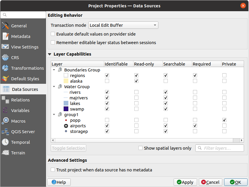
Abb. 9.34 Data Sources tab
9.3.8. Relations Properties
The  Relations tab is used to define 1:n relations and
polymorphic relations. The relations
are defined in the project properties dialog. Once relations exist for a layer,
a new user interface element in the form view (e.g. when identifying a feature
and opening its form) will list the related entities. This provides a powerful
way to express e.g. the inspection history on a length of pipeline or road segment.
You can find out more about 1:n relations support in Section Creating one or many to many relations.
Relations tab is used to define 1:n relations and
polymorphic relations. The relations
are defined in the project properties dialog. Once relations exist for a layer,
a new user interface element in the form view (e.g. when identifying a feature
and opening its form) will list the related entities. This provides a powerful
way to express e.g. the inspection history on a length of pipeline or road segment.
You can find out more about 1:n relations support in Section Creating one or many to many relations.
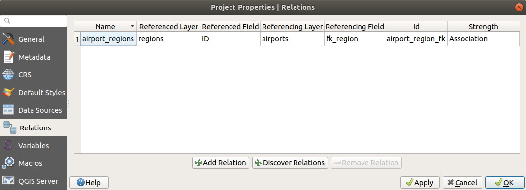
Abb. 9.35 Relations tab
9.3.9. Eigenschafen Variablen
The  Variables tab lists all the variables available at
the project’s level (which includes all global variables). Besides, it
also allows the user to manage project-level variables. Click the
button to add a new custom project-level variable. Likewise, select a custom
project-level variable from the list and click the button to
remove it.
More information on variables usage in the General Tools
Storing values in Variables section.
Variables tab lists all the variables available at
the project’s level (which includes all global variables). Besides, it
also allows the user to manage project-level variables. Click the
button to add a new custom project-level variable. Likewise, select a custom
project-level variable from the list and click the button to
remove it.
More information on variables usage in the General Tools
Storing values in Variables section.
9.3.10. Macros Properties
The  Macros tab is used to edit Python macros for projects.
Currently, only three macros are available:
Macros tab is used to edit Python macros for projects.
Currently, only three macros are available: openProject(), saveProject()
and closeProject().
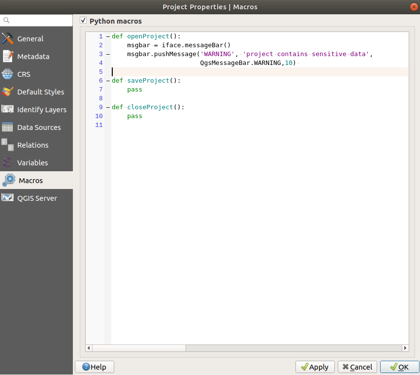
Abb. 9.36 Macro settings
9.3.11. Eigenschaften QGIS Server
The QGIS Server tab allows you to configure your project
in order to publish it online. Here you can define information about the QGIS
Server WMS and WFS capabilities, extent and CRS restrictions. More information
available in section Configure your project and subsequent.
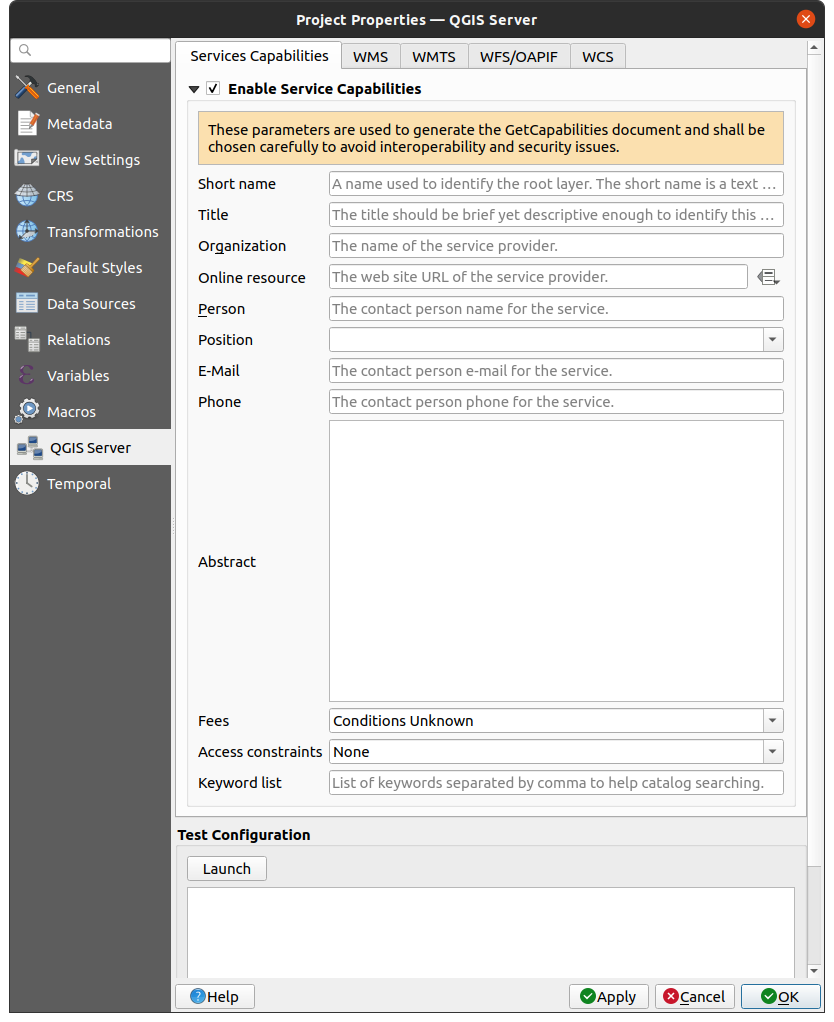
Abb. 9.37 QGIS Server settings
9.3.12. Eigenschaften Zeitlich
The  Temporal tab is used to set the temporal range of your project,
either by using manual Start date and End date inputs
or by calculating it from the current project temporal layers.
The project time range can then be used in the Temporal controller
panel to manage the map canvas temporal navigation.
Temporal tab is used to set the temporal range of your project,
either by using manual Start date and End date inputs
or by calculating it from the current project temporal layers.
The project time range can then be used in the Temporal controller
panel to manage the map canvas temporal navigation.
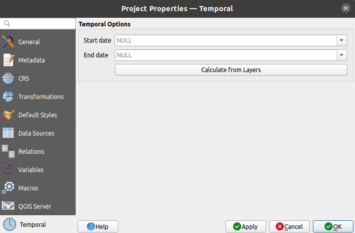
Abb. 9.38 Project Temporal tab
9.3.13. Terrain Properties
The  Terrain tab helps you configure default settings
for the terrain and elevation. When any new 3d map
is created in the project, the map will default to using the same terrain
settings as are defined for the project.
The project elevation settings will also be respected by the Profile tool.
Terrain tab helps you configure default settings
for the terrain and elevation. When any new 3d map
is created in the project, the map will default to using the same terrain
settings as are defined for the project.
The project elevation settings will also be respected by the Profile tool.
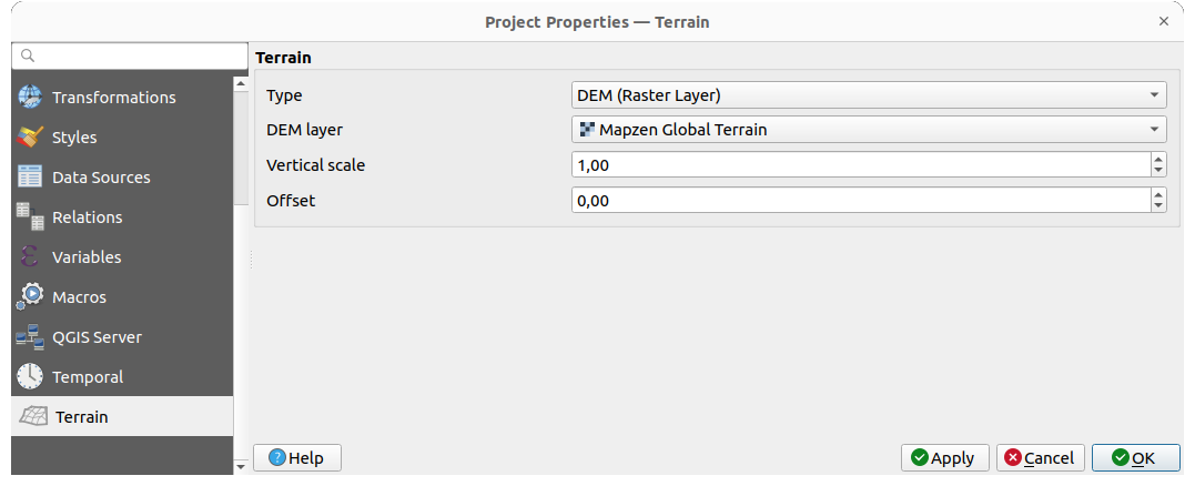
Abb. 9.39 Project Terrain tab
Terrain and elevation options are available for:
Flat terrain with Terrain height setting
DEM (Raster Layer): with setting for defining the Raster layer, a Vertical scale factor to apply to band values and a vertical Offset
Mesh: with setting for defining the Mesh layer, a Vertical scale factor to apply to vertices Z value and a vertical Offset
These settings can be overwritten from the 3D map configuration dialog.
9.4. Anpassung
The Customization dialog lets you (de)activate almost every element in the QGIS user interface. This can be very useful if you want to provide your end-users with a ‚light‘ version of QGIS, containing only the icons, menus or panels they need.
Bemerkung
Bevor Ihre Änderungen übernommen werden, müssen Sie QGIS neu starten.
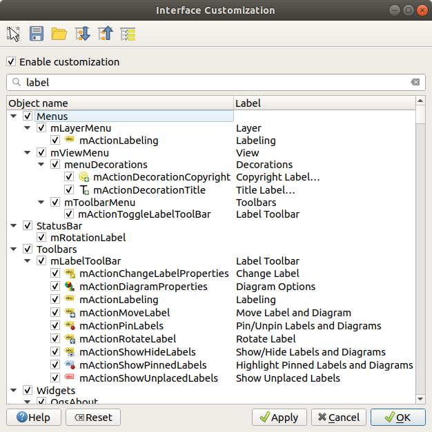
Abb. 9.40 Der Anpassung Dialog
Die Anpassung aktivieren Checkbox anzuklicken ist der erste Schritt, zur QGIS Anpassung. Dies aktiviert die Werkzeugleiste und das Widget-Panel, hier können Sie einige QGIS Elemente unsichtbar schalten.
Die konfigurierbaren Elemente können sein:
ein Menü oder einige ihrer Untermenüs von dem Menüleiste
das komplette Panel (siehe Bedienfelder und Werkzeugkästen)
die Statusleiste beschrieben in Statusleiste oder einige ihrer Elemente
eine Werkzeugleiste: die komplette oder einige ihrer Icons
oder irgendein Widget aus irgendeinem QGIS Dialog: Beschriftung, Knöpfe, Komboboxen…
With  Switch to catching widgets in main application, you
can click on an item in QGIS interface that you want to be hidden and
QGIS automatically unchecks the corresponding entry in the Customization dialog.
You can also use the Search box to find items by their name or label.
Switch to catching widgets in main application, you
can click on an item in QGIS interface that you want to be hidden and
QGIS automatically unchecks the corresponding entry in the Customization dialog.
You can also use the Search box to find items by their name or label.
Once you setup your configuration, click Apply or OK to validate your changes. This configuration becomes the one used by default by QGIS at the next startup.
Die Modifikationen können auch in einer .ini Datei gespeichert werden unter Verwendung des Als Datei speichern Knopfs. Dies ist eine praktische Möglichkeit, eine gemeinsame QGIS Schnittstelle zwischen mehreren Benutzern zu teilen. Klicken Sie einfach auf Laden von Datei von dem Zielcomputer aus, um die``.ini`` Datei zu importieren. Sie können auch command line tools starten und verschiedene Einstellungen für verschiedene Anwendungsfälle speichern.
Tipp
Voreingestelltes QGIS einfach wiederherstellen
Die erste QGIS GUI-Konfiguration kann durch eine der Methoden unten wiederhergestellt werden:
deaktivieren Sie
Anpassung aktivieren im Anpassungsdialog oder klicken Sie  Alle überprüfen
pressing the Reset button in the Settings frame under menu, System tab
starte QGIS an einer Eingabeaufforderung mit der folgenden Befehlszeile
qgis --customizationsetting to
falsethe value of variable under menu, Advanced tab (see the warning).
In den meisten Fällen müssen Sie QGIS neu starten, damit die Änderungen angewendet werden.
9.5. Tastenkürzel
QGIS provides default keyboard shortcuts for many features. You can find them in
section Menüleiste. Additionally, the menu option
allows you to change the default keyboard shortcuts and add new
ones to QGIS features.
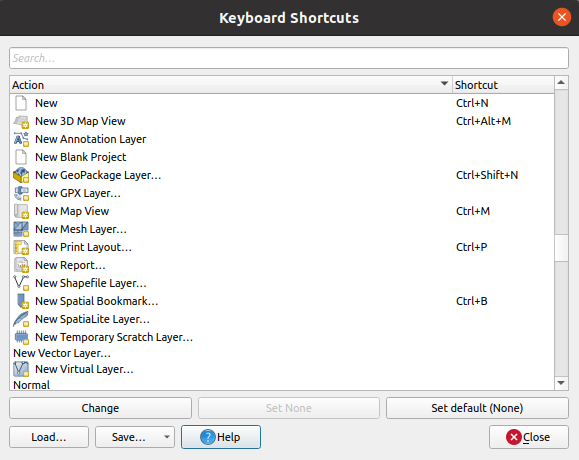
Abb. 9.41 Define shortcut options
Configuration is very simple. Use the search box at the top of the dialog to find a particular action, select it from the list and click on :
Change and press the new combination you want to assign as new shortcut
Set None to clear any assigned shortcut
or Set Default to backup the shortcut to its original and default value.
Proceed as above for any other tools you wish to customize. Once you have
finished your configuration, simply Close the dialog to have your changes
applied. You can also Save the changes either as an .XML file
with only the User Shortcuts or with all Shortcuts or as an .PDF file with
all Shortcuts and Load them into another QGIS installation.
9.6. Running QGIS with advanced settings
9.6.1. Command line and environment variables
We’ve seen that launching QGIS is done as for any
application on your OS.
QGIS provides command line options for more advanced use cases (in some cases
you can use an environment variable instead of the command line option).
To get a list of the options, enter qgis --help on the command line, which
returns:
QGIS is a user friendly Open Source Geographic Information System.
Usage: /usr/bin/qgis.bin [OPTION] [FILE]
  OPTION:
        [-v, --version]     display version information and exit
        [-s, --snapshot filename]   emit snapshot of loaded datasets to given file
        [-w, --width width] width of snapshot to emit
        [-h, --height height]       height of snapshot to emit
        [-l, --lang language]       use language for interface text (changes existing override)
        [-p, --project projectfile] load the given QGIS project
        [-e, --extent xmin,ymin,xmax,ymax]  set initial map extent
        [-n, --nologo]      hide splash screen
        [-V, --noversioncheck]      don't check for new version of QGIS at startup
        [-P, --noplugins]   don't restore plugins on startup
        [-B, --skipbadlayers]     don't prompt for missing layers
        [-C, --nocustomization]     don't apply GUI customization
        [-z, --customizationfile path]      use the given ini file as GUI customization
        [-g, --globalsettingsfile path]     use the given ini file as Global Settings (defaults)
        [-a, --authdbdirectory path] use the given directory for authentication database
        [-f, --code path]   run the given python file on load
        [-d, --defaultui]   start by resetting user ui settings to default
        [--hide-browser]        hide the browser widget
        [--dxf-export filename.dxf]     emit dxf output of loaded datasets to given file
        [--dxf-extent xmin,ymin,xmax,ymax]      set extent to export to dxf
        [--dxf-symbology-mode none|symbollayer|feature] symbology mode for dxf output
        [--dxf-scale-denom scale]       scale for dxf output
        [--dxf-encoding encoding]       encoding to use for dxf output
        [--dxf-map-theme maptheme]      map theme to use for dxf output
        [--take-screenshots output_path]        take screen shots for the user documentation
        [--screenshots-categories categories]   specify the categories of screenshot to be used (see QgsAppScreenShots::Categories).
        [--profile name]        load a named profile from the user's profiles folder.
        [-S, --profiles-path path]  path to store user profile folders. Will create profiles inside a {path}\profiles folder
        [--version-migration]   force the settings migration from older version if found
        [--openclprogramfolder]         path to the folder containing the sources for OpenCL programs.
        [--help]                this text
        [--]            treat all following arguments as FILEs

  FILE:
    Files specified on the command line can include rasters,
    vectors, and QGIS project files (.qgs and .qgz):
     1. Rasters - supported formats include GeoTiff, DEM
        and others supported by GDAL
     2. Vectors - supported formats include ESRI Shapefiles
        and others supported by OGR and PostgreSQL layers using
        the PostGIS extension
Tipp
Example Using command line arguments
You can start QGIS by specifying one or more data files on the command
line. For example, assuming you are in the qgis_sample_data
directory, you could start QGIS with a vector layer and a raster file
set to load on startup using the following command:
qgis ./raster/landcover.img ./gml/lakes.gml
9.6.1.1. --version
This option returns QGIS version information.
9.6.1.2. --snapshot
This option allows you to create a snapshot in PNG format from the current view. This comes in handy when you have many projects and want to generate snapshots from your data, or when you need to create snapshots of the same project with updated data.
Currently, it generates a PNG file with 800x600 pixels. The size can be adjusted
using the --width and --height arguments. The filename can
be added after --snapshot. For example:
qgis --snapshot my_image.png --width 1000 --height 600 --project my_project.qgs
9.6.1.3. --width
This option returns the width of the snapshot to be emitted (used with --snapshot).
9.6.1.4. --height
This option returns the height of the snapshot to be emitted (used with --snapshot).
9.6.1.5. --lang
Based on your locale, QGIS selects the correct localization. If you would like
to change your language, you can specify a language code. For example,
qgis --lang it starts QGIS in Italian localization.
9.6.1.6. --project
Starting QGIS with an existing project file is also possible. Just add the
command line option --project followed by your project name and QGIS will
open with all layers in the given file loaded.
9.6.1.7. --extent
To start with a specific map extent use this option. You need to add the bounding box of your extent in the following order separated by a comma:
--extent xmin,ymin,xmax,ymax
This option probably makes more sense when paired with the --project option
to open a specific project at the desired extent.
9.6.1.8. --nologo
This option hides the splash screen when you start QGIS.
9.6.1.9. --noversioncheck
Skip searching for a new version of QGIS at startup.
9.6.1.10. --noplugins
If you have trouble at start-up with plugins, you can avoid loading them at start-up with this option. They will still be available from the Plugins Manager afterwards.
9.6.1.11. --nocustomization
Using this option, any existing GUI customization will not be applied at startup. This means that any hidden buttons, menu items, toolbars, and so on, will show up on QGIS start up. This is not a permanent change. The customization will be applied again if QGIS is launched without this option.
This option is useful for temporarily allowing access to tools that have been removed by customization.
9.6.1.12. --skipbadlayers
Using this option, you can avoid QGIS prompting the Handle Unavailable Layers dialog at startup. The project file is loaded, with missing layers kept as unavailable. More details on the topic at Behandlung von zerstörten Dateipfaden.
9.6.1.13. --customizationfile
Using this option, you can define a UI customization file, that will be used at startup.
9.6.1.14. --globalsettingsfile
The equivalent environment variable is QGIS_GLOBAL_SETTINGS_FILE.
Using this option, you can specify the path for a Global Settings
file (.ini), also known as the Default Settings. The settings in the specified
file replace the original inline default ones, but the user profiles‘
settings will be set on top of those.
QGIS looks for the default global settings file in the following order and only the first found file will be used:
path specified by the commandline parameter
path defined by the environment variable
the AppDataLocation folder, where persistent application data can be stored; it is managed by the user or system administrator and is not touched by installer and does not require any additional setup like passing commandline parameters or settings environment variable. Depending on the OS, it is:
-
$HOME/.local/share/QGIS/QGIS3/ -
C:\Users\<username>\%AppData%\Roaming\QGIS\QGIS3\ -
$HOME/Library/Application Support/QGIS/QGIS3/
the installation directory, i.e.
your_QGIS_package_path/resources/qgis_global_settings.ini.
Presently, there’s no way to specify a file to write settings to; therefore, you can create a copy of an original settings file, rename, and adapt it.
Setting the qgis_global_setting.ini file path to a network shared
folder, allows a system administrator to change global settings and defaults in
several machines by only editing one file.
9.6.1.15. --authdbdirectory
This option is similar to --globalsettingsfile, but defines the path to the
directory where the authentication database will be stored and loaded.
9.6.1.16. --code
This option can be used to run a given python file directly after QGIS has started.
For example, when you have a python file named load_alaska.py with
following content:
from qgis.utils import iface
raster_file = "/home/gisadmin/Documents/qgis_sample_data/raster/landcover.img"
layer_name = "Alaska"
iface.addRasterLayer(raster_file, layer_name)
Assuming you are in the directory where the file load_alaska.py is
located, you can start QGIS, load the raster file landcover.img and give
the layer the name ‚Alaska‘ using the following command:
qgis --code load_alaska.py
9.6.1.17. --defaultui
On load, permanently resets the user interface (UI) to the default settings. This option will restore the panels and toolbars visibility, position, and size. Unless it’s changed again, the default UI settings will be used in the following sessions.
Notice that this option doesn’t have any effect on GUI customization.
Items hidden by GUI customization (e.g. the status bar) will remain hidden
even using the --defaultui option.
See also the --nocustomization option.
9.6.1.18. --hide-browser
On load, hides the Browser panel from the user interface. The panel
can be enabled by right-clicking a space in the toolbars or using the
( in  Linux KDE).
Unless it’s enabled again, the Browser panel will remain hidden in the following sessions.
9.6.1.19. --dxf-*
These options can be used to export a QGIS project into a DXF file. Several options are available:
–dxf-export: the DXF filename into which to export the layers;
–dxf-extent: the extent of the final DXF file;
–dxf-symbology-mode: several values can be used here:
none(no symbology),symbollayer(Symbol layer symbology),feature(feature symbology);–dxf-scale-denom: the scale denominator of the symbology;
–dxf-encoding: the file encoding;
–dxf-map-theme: choose a map theme from the layer tree configuration.
9.6.1.20. --take-screenshots
Takes screenshots for the user documentation. Can be used together with
--screenshots-categories to filter which categories/sections of the
documentation screenshots should be created (see QgsAppScreenShots::Categories).
9.6.1.21. --profile
Loads QGIS using a specific profile from the user’s profile folder. Unless changed, the selected profile will be used in the following QGIS sessions.
9.6.1.22. --profiles-path
With this option, you can choose a path to load and save the profiles (user
settings). It creates profiles inside a {path}\profiles folder, which
includes settings, installed plugins, processing models and scripts, and so on.
This option allows you to, for instance, carry all your plugins and settings in a flash drive, or, for example, share the settings between different computers using a file sharing service.
The equivalent environment variable is QGIS_CUSTOM_CONFIG_PATH.
9.6.1.23. --version-migration
If settings from an older version are found (e.g., the .qgis2 folder from QGIS
2.18), this option will import them into the default QGIS profile.
9.6.1.24. --openclprogramfolder
Using this option, you can specify an alternative path for your OpenCL programs. This is useful for developers while testing new versions of the programs without needing to replace the existing ones.
The equivalent environment variable is QGIS_OPENCL_PROGRAM_FOLDER.
9.6.2. Deploying QGIS within an organization
If you need to deploy QGIS within an organization with a custom configuration file,
first you need to copy/paste the content of the default settings file located in
your_QGIS_package_path/resources/qgis_global_settings.ini. This file already
contains some default sections identified by a block starting with [].
We recommend that you keep these defaults values and add your own sections at the bottom
of the file. If a section is duplicated in the file, QGIS will take the last
one from top to bottom.
You can change allowVersionCheck=false to disable
the QGIS version check.
If you do not want to display the migration window after a fresh install, you need the following section:
[migration]
fileVersion=2
settings=true
If you want to add a custom variable in the global scope:
[variables]
organisation="Your organization"
To discover the possibilities of the settings INI file, we suggest that you set
the config you would like in QGIS Desktop and then search for it in your INI
file located in your profile using a text editor. A lot of settings can be set
using the INI file such as WMS/WMTS, PostGIS connections, proxy settings, maptips…
Finally, you need to set the environment variable QGIS_GLOBAL_SETTINGS_FILE
to the path of your customized file.
In addition, you can also deploy files such as Python macros, color palettes, layout templates, project templates… either in the QGIS system directory or in the QGIS user profile.
Layout templates must be deployed in the
composer_templatesdirectory.Project templates must be deployed in the
project_templatesdirectory.Custom Python macros must be deployed in the
pythondirectory.