13.4. Creando Símbolos 3D
El Administrador de estilo le ayuda a crear y almacenar símbolos 3D para cada tipo de geometría a renderizar en la vista de mapa 3D.
En cuanto a los demás elementos, habilitar la pestaña  Símbolos 3D y expanda el menú del botón
  para crear:
13.4.1. Capas de puntos
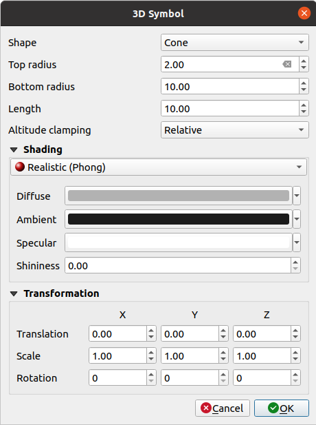
Figura 13.29 Propiedades de un símbolo de punto 3D
Puede definir diferentes tipos de Forma 3D para usar con símbolos de puntos. Se definen principalmente por sus dimensiones cuya unidad se refiere al SRC del proyecto. Los tipos disponibles son:
Esfera definida por un Radio
Cilindro definido por un Radio y Longitud
Cubo definido por un Tamaño
Cono definido por un Radio superior, un Radio inferior y un Longitud
Plano definido por un Tamaño
Toroide definido por un Radio y un Radio menor
Modelo 3D, utilizando un archivo de modelo 3D (se admiten varios formatos) que puede ser un archivo en disco, una URL remota o embedded in the project.
Valla publicitaria, definida por la Altura de la valla publicitaria y el Símbolo de la valla publicitaria (generalmente basado en un:ref:marker symbol <vector_marker_symbols>). El símbolo tendrá un tamaño estable. Conveniente para visualizar formas de nubes de puntos 3D.
El Sujeción de altitud se puede configurar en Absoluto, Relativo o Terreno. La configuración Absoluto se puede usar cuando los valores de altura de los vectores 3d se proporcionan como medidas absolutas desde 0. Relativo y Terreno agregan valores de elevación dados a la elevación del terreno subyacente.
The shading Puede ser definido.
Bajo el cuadro Transformaciones, puede aplicar una transformación afín al símbolo:
Translación para mover objetos en los ejes x, y y z.
Escala para cambiar el tamaño de las formas 3D
Rotación alrededor del eje x, y y z.
13.4.2. Capas lineales
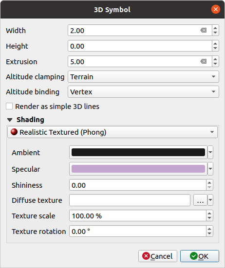
Figura 13.30 Propiedades de símbolo lineal 3D
Debajo de las configuraciones Anchura y Altura puede definir Extrusión de las líneas vectoriales. Si las líneas no tienen valores z, puede definir los volúmenes 3d con esta configuración.
Con Fijación de altitud, define la posición de las líneas 3D en relación con la superficie del terreno subyacente, si ha incluido datos de elevación ráster u otros vectores 3D.
La Altitud de enlazado define cómo se fija el objeto al terreno. O cada Vértice de la entidad se sujetará al terreno o esto se hará por Centroide.
Es posible
 Renderizar como líneas simpes 3D.
El sombreado pude definirse en los menues Difuso, Ambiental, Especular y Brillante.
13.4.3. Capas Poligonales
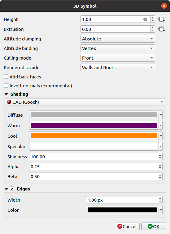
Figura 13.31 Propiedades de un símbolo poligonal 3D
Como los demás, la Altura se puede definir en unidades SRC. También puede utilizar el botón
 para sobrescribir el valor con una expresión personalizada, una variable o una entrada de la tabla de atributos
Nuevamente, la Extrusion es posible para valores z faltantes. También para la extrusión puede utilizar
para usar los valores de la capa vectorial y tener diferentes resultados para cada polígono: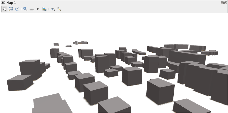
Figura 13.32 Extrusión Definida por Datos
La Altitud de anclaje, Altitud de enlazado puede ser definida como se explica arriba.
El :guilabel:``Modo de selección` a aplicar al símbolo; puede ser:
No Culling: esto puede ayudar a evitar superficies aparentemente faltantes cuando los datos de polígonoZ/multiparche no tienen un orden consistente de vértices (por ejemplo, todo en el sentido de las agujas del reloj o en sentido contrario)
parte delantera
or parte trasera
La Fachada renderizada determina las caras a mostrar. Los valores posibles son Sin fachadas, Muros, Cubiertas, o Muros y cubiertas
- :guilabel:`Agregar caras posteriores” para cada triángulo, crea caras frontal y posterior con las normales correctas, a expensas de un mayor número de datos de vértice. Esta opción se puede usar para corregir problemas de sombreado (por ejemplo, debido a datos con un orden de vértices inconsistente).
- Invertir normales (experimental): puede ser útil para fijar órdenes de vértice de cara en sentido horario/antihorario
The shading Puede ser definido.
visualización de los símbolos
Bordes se puede habilitar y asignar un Ancho y Color.
Consejo
Combinación para la mejor representación de datos 3D
Culling mode, Agregar cara posterior y Invert normales tienen como objetivo corregir el aspecto de los datos 3D si no se ve bien. Por lo general, cuando se cargan algunos datos, lo mejor es probar primero culling mode=back y add back faces=disabled; es lo más eficiente. Si el renderizado no se ve correcto, intente agregar caras traseras=habilitado y mantenga el modo de selección=sin selección. Otras combinaciones son más avanzadas y útiles solo en algunos escenarios según cuán mezclado esté el conjunto de datos de entrada.
13.4.4. Sombreando la textura
El sombreado te ayuda a revelar detalles en 3D de objetos que, de lo contrario, podrían estar ocultos debido a la iluminación de la escena. En última instancia, es un material más fácil para trabajar, ya que no necesita preocuparse por configurar la iluminación de escena adecuada para visualizar las características.
En QGIS se utilizan varias técnicas de sombreado y su disponibilidad depende del tipo de geometría del símbolo:
Realista (Phong): describe la forma en que una superficie refleja la luz como una combinación del Difuso reflejo de superficies rugosas con el Especular reflejo de superficies brillantes (Brillo `). También incluye una opción :guilabel:`Ambient para tener en cuenta la pequeña cantidad de luz que se dispersa por toda la escena. Lea más en https://en.wikipedia.org/wiki/Phong_reflection_model#Description
Textura Realista (Phong): igual que Realista (Phong) excepto que se utiliza una imagen como Textura Difusa. La imagen puede ser un archivo en el disco, una URL remota o incrustada en el proyecto. La Escala de textura y la Rotación de textura son obligatorias.
CAD (Gooch): esta técnica permite que el sombreado ocurra solo en tonos medios para que las líneas de borde y los reflejos permanezcan visualmente prominentes. Junto con las opciones Diffuse, Specular, Shininess, debe proporcionar un color Warm (para la superficie orientada hacia la luz) y un :guilabel: Color cool (para los que están de espaldas). Además, las contribuciones relativas a los colores fríos y cálidos por parte del color difuso están controladas por las propiedades Alpha y Beta respectivamente. Ver también https://en.wikipedia.org/wiki/Gooch_shading
Texturas Embebidas con forma de modelos 3D
13.4.5. Ejemplo de Aplicación
Para ir a través de los ajustes explicados arriba puede echar un vistazo a https://app.merginmaps.com/projects/saber/luxembourg/tree.