11.2. Creating Layers
Layers can be created in many ways, including:
empty layers from scratch
layers from existing layers
layers from the clipboard
layers as a result of an SQL-like query based on one or many layers (virtual layers)
QGIS also provides tools to import/export from/to different formats.
11.2.1. Creating new vector layers
QGIS allows you to create new layers in different formats. It provides tools for creating GeoPackage, Shapefile, SpatiaLite, GPX format and Temporary Scratch layers (aka memory layers). Creation of a new GRASS layer is supported within the GRASS plugin.
11.2.1.1. Creating a new GeoPackage layer
To create a new GeoPackage layer, press the  button in the
menu or from the
Data Source Manager toolbar.
You can also create a new GeoPackage layer through the Browser Panel
by selecting the Create Database and Layer….
The New GeoPackage Layer dialog will be displayed as shown in
Fig. 11.26.
button in the
menu or from the
Data Source Manager toolbar.
You can also create a new GeoPackage layer through the Browser Panel
by selecting the Create Database and Layer….
The New GeoPackage Layer dialog will be displayed as shown in
Fig. 11.26.
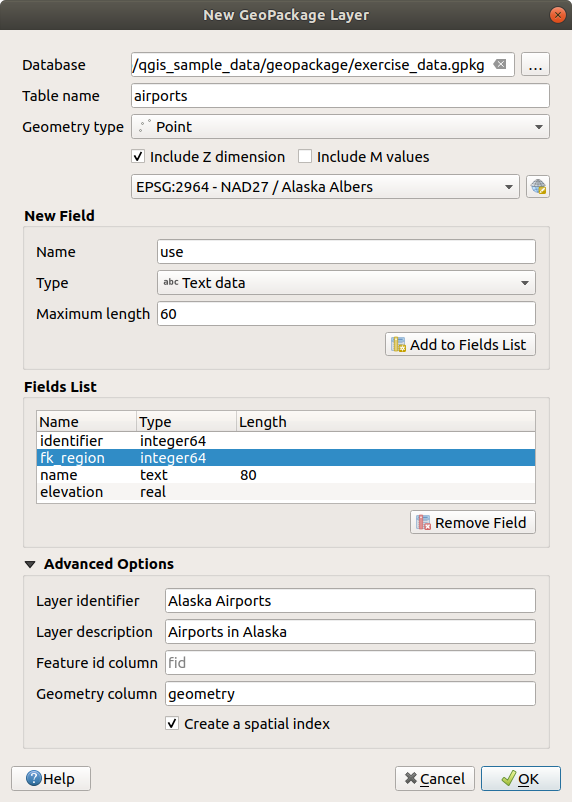
Fig. 11.26 Creating a New GeoPackage layer dialog
The first step is to indicate the database file location. This can be done by pressing the … button to the right of the Database field and select an existing GeoPackage file or create a new one. QGIS will automatically add the right extension to the name you provide.
Give the new layer / table a name (Table name)
Define the Geometry type. If not a geometryless layer, you can specify whether it should Include Z dimension and/or Include M values.
Specify the coordinate reference system using the
 button
To add fields to the layer you are creating:
Enter the Name of the field
Select the data Type. Supported types are Text data, Whole number (both integer and integer64), Decimal number, Date and Date and time, Binary (BLOB) and Boolean.
Depending on the selected data format, enter the Maximum length of values.
Click on the
 Add to Fields List button
Reproduce the steps above for each field you need to add
You can later change the fields order using the
 Move Up
and
Move Up
and  Move Down buttons
Once you are happy with the attributes, click OK. QGIS will add the new layer to the legend, and you can edit it as described in section Digitizing an existing layer.
By default, when creating a GeoPackage layer, QGIS generates a
Feature id column called fid which acts as the
primary key of the layer. The name can be changed.
The geometry field, if available, is named geometry, and you can
choose to Create a spatial index on it.
These options can be found under the Advanced Options
together with the Layer identifier (short human readable
name of the layer) and the Layer description.
Further management of GeoPackage layers can be done with the DB Manager.
11.2.1.2. Creating a new Shapefile layer
To create a new ESRI Shapefile format layer, press the  button in the
menu or from the
Data Source Manager toolbar.
The New Shapefile Layer dialog will be displayed as shown in
Fig. 11.27.
button in the
menu or from the
Data Source Manager toolbar.
The New Shapefile Layer dialog will be displayed as shown in
Fig. 11.27.
Provide a path and file name using the … button next to File name. QGIS will automatically add the right extension to the name you provide.
Next, indicate the File encoding of the data
Choose the Geometry type of the layer: No Geometry (resulting in a
.DBFformat file), point, multipoint, line or polygonSpecify whether the geometry should have additional dimensions: None, Z (+ M values) or M values
Specify the coordinate reference system using the
button
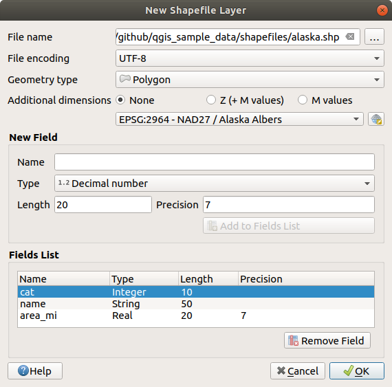
Fig. 11.27 Creating a new Shapefile layer dialog
To add fields to the layer you are creating:
Enter the Name of the field
Select the data Type. Only Decimal number, Whole number, Text data, Date, and Boolean data types attributes are supported.
Depending on the selected data format, enter the Length and Precision.
Click on the
Add to Fields List buttonReproduce the steps above for each field you need to add
You can later change the fields order using the
Move Up
and Move Down buttonsOnce you are happy with the attributes, click OK. QGIS will add the new layer to the legend, and you can edit it as described in section Digitizing an existing layer.
By default, a first integer id column is added but can be removed.
11.2.1.3. Creating a new SpatiaLite layer
To create a new SpatiaLite layer, press the  button in the menu or from the Data Source Manager toolbar.
The New SpatiaLite Layer dialog will be displayed as shown in
Fig. 11.28.
button in the menu or from the Data Source Manager toolbar.
The New SpatiaLite Layer dialog will be displayed as shown in
Fig. 11.28.
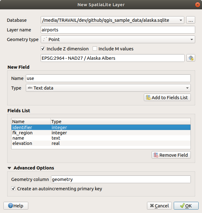
Fig. 11.28 Creating a New SpatiaLite layer dialog
The first step is to indicate the database file location. This can be done by pressing the … button to the right of the Database field and select an existing SpatiaLite file or create a new one. QGIS will automatically add the right extension to the name you provide.
Provide a name (Layer name) for the new layer
Define the Geometry type. If not a geometryless layer, you can specify whether it should Include Z dimension and/or Include M values.
Specify the coordinate reference system using the
button.
To add fields to the layer you are creating:
Enter the Name of the field
Select the data Type. Supported types are Text data, Whole number, Decimal number, Date and Date time.
Click on the
Add to Fields List buttonReproduce the steps above for each field you need to add
You can later change the fields order using the
Move Up
and Move Down buttonsOnce you are happy with the attributes, click OK. QGIS will add the new layer to the legend, and you can edit it as described in section Digitizing an existing layer.
If desired, you can select  Create an autoincrementing
primary key under the Advanced Options section. You can also rename
the Geometry column (
Create an autoincrementing
primary key under the Advanced Options section. You can also rename
the Geometry column (geometry by default).
Further management of SpatiaLite layers can be done with DB Manager.
11.2.1.4. Creating a new Mesh layer
To create a new Mesh layer, press the  button in the
menu or from the
Data Source Manager toolbar.
The New Mesh Layer dialog will be displayed as shown in
Fig. 11.29.
button in the
menu or from the
Data Source Manager toolbar.
The New Mesh Layer dialog will be displayed as shown in
Fig. 11.29.
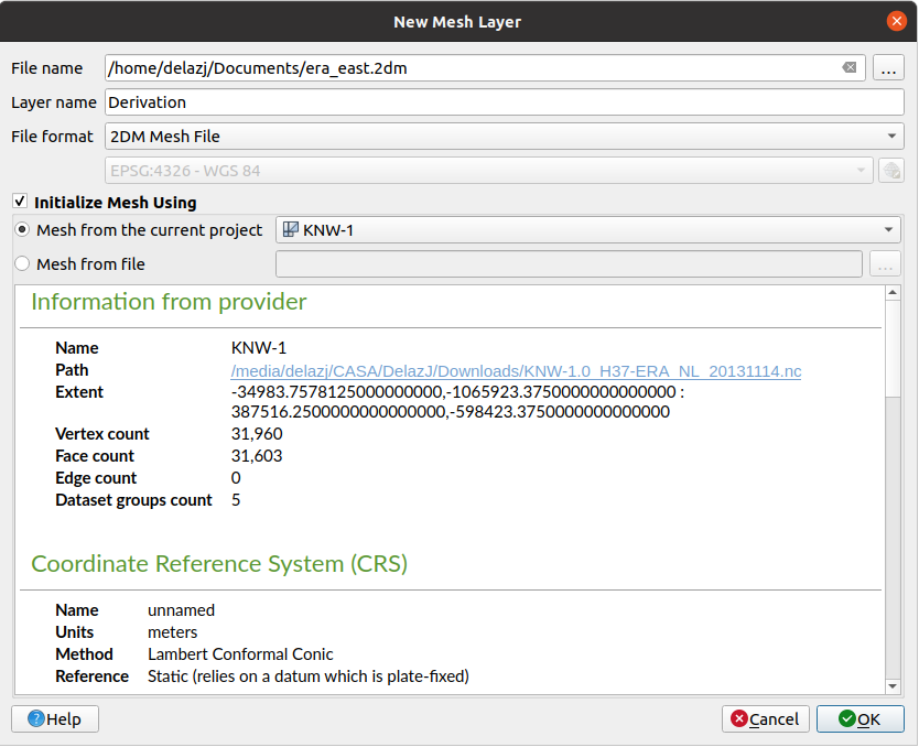
Fig. 11.29 Creating a New Mesh layer dialog
The first step is to indicate the mesh file location. This can be done by pressing the … button to the right of the File name field and select an existing mesh file or create a new one.
Provide a name (Layer name), i.e. the name the layer is displayed with in the Layers panel
Select the File format: currently supported mesh file formats are
2DM Mesh File (*.2dm),Selafin File (*.slf)andUGRID (*.nc).Indicate the Coordinate Reference System to assign to the dataset
The above steps will generate an empty layer that you can afterwards digitize vertices and add dataset groups to. It’s however also possible to initialize the layer with an existing mesh layer, i.e. populate the new layer with vertices or faces from the other. To do so:
Check
Initialize Mesh usingand select either a Mesh from the current project or Mesh from a file. Information on the selected mesh file are displayed for checkup.
Note that only the frame of the mesh layer is transferred to the new layer; their datasets are not copied.
11.2.1.5. Creating a new GPX layer
To create a new GPX file:
Select
 from the menu.
In the dialog, choose where to save the new file, name it and press Save.
Three new layers are added to the Layers Panel:
a point layer to digitize locations (
waypoints) with fields storing the name, elevation, comment, description, source, url and url namea line layer to digitize sequences of locations that make up a planned route (
routes) with fields storing the name, symbol, number, comment, description, source, url, url nameand a line layer to track the receiver’s movement over time (
tracks) with fields storing the name, symbol, number, comment, description, source, url, url name.
You can now edit any of them as described in section Digitizing an existing layer.
11.2.1.6. Creating a new Temporary Scratch Layer
Temporary Scratch Layers are in-memory layers, meaning that they are not saved on disk and will be discarded when QGIS is closed. They can be handy for storing features you temporarily need or as intermediate layers during geoprocessing operations.
To create a new Temporary Scratch layer, choose the  entry in the
menu or in the Data
Source Manager toolbar.
The New Temporary Scratch Layer dialog will be displayed as shown in
Fig. 11.30. Then:
entry in the
menu or in the Data
Source Manager toolbar.
The New Temporary Scratch Layer dialog will be displayed as shown in
Fig. 11.30. Then:
Provide the Layer name
Select the Geometry type. Here you can create a:
No Geometrytype layer, served as simple table,PointorMultiPointlayer,LineStringorMultiLinelayer,CompoundCurve,MultiCurveorNurbsCurvelayer,PolygonorMultiPolygonlayer,CurvePolygonorMultiSurfacelayer,Triangle,PolyhedralSurfaceorTINlayer.
For geometric types, specify the dimensions of the dataset: check whether it should Include Z dimension and/or Include M values
Specify the coordinate reference system using the
button.Add fields to the layer. Note that unlike many formats, temporary layers can be created without any fields. This step is thus optional.
Enter the Name of the field
Select the data Type: Text, Whole number, Decimal number, Boolean, Date, Time, Date & Time and Binary (BLOB) are supported.
Depending on the selected data format, enter the Length and Precision
Click on the
Add to Fields List buttonRepeat the steps above for each field you need to add
You can later change the fields order using the
Move Up
and Move Down buttons
Once you are happy with the settings, click OK. QGIS will add the new layer to the Layers panel, and you can edit it as described in section Digitizing an existing layer.
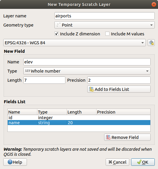
Fig. 11.30 Creating a new Temporary Scratch layer dialog
You can also create prepopulated temporary scratch layers using e.g. the clipboard (see Creating new layers from the clipboard) or as a result of a Processing algorithm.
Tip
Permanently store a memory layer on disk
To avoid data loss when closing a project with temporary scratch layers, you can save these layers to any vector format supported by QGIS:
clicking the
 indicator icon next to the layer;
selecting the Make permanent entry in the layer contextual menu;
using the entry from the contextual menu or the menu.
Each of these commands opens the Save Vector Layer as dialog described in the Creating new layers from an existing layer section and the saved file replaces the temporary one in the Layers panel. If the saved file name is different from the original one in the Layers panel, a message bar will pop up, and you can click the Rename layer in layers panel button to homogenize the naming.
11.2.2. Creating new layers from an existing layer
Layers (raster, vector and point cloud) can be saved in a different format and/or reprojected to a different coordinate reference system (CRS) using the menu or right-clicking on the layer in the Layers panel and selecting:
for raster and point cloud layers
or for vector layers.
Drag and drop the layer from the layer tree to the PostgreSQL entry in the Browser Panel. Note that you must have a PostgreSQL connection in the Browser Panel.
11.2.2.1. Common parameters
The Save Layer as… dialog shows several parameters to change the behavior when saving the layer. Among the common parameters for raster and vector are:
File name: the location of the file on the disk. It can refer to the output layer or to a container that stores the layer (for example database-like formats such as GeoPackage, SpatiaLite or Open Document Spreadsheets).
CRS: can be changed to reproject the data
Extent: restricts the extent of the input that is to be exported using the extent_selector widget
Add saved file to map: to add the new layer to the canvas
However, some parameters are specific to certain formats:
11.2.2.2. Raster specific parameters
Depending on the format of export, some of these options may not be available:
Output mode (it can be raw data or rendered image)
Format: exports to any raster format GDAL can write to, such as GeoTiff, GeoPackage, MBTiles, Geospatial PDF, SAGA GIS Binary Grid, Intergraph Raster, ESRI .hdr Labelled…
Resolution
Create Options: use advanced options (file compression, block sizes, colorimetry…) when generating files, either from the predefined create profiles related to the output format or by setting each parameter.
Pyramids creation
VRT Tiles in case you opted to
Create VRTNo data values
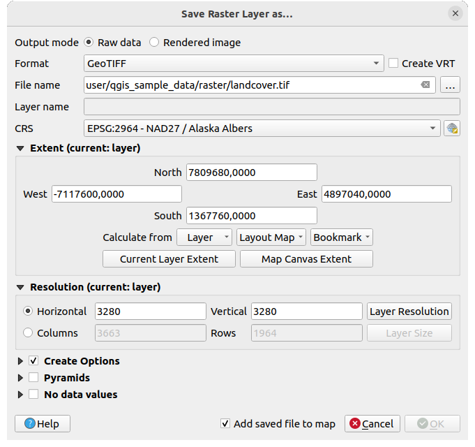
Fig. 11.31 Saving as a new raster layer
11.2.2.3. Vector specific parameters
Depending on the format of export, some of these options may be available:
Format: exports to any vector format GDAL can write to, such as GeoPackage, GML, ESRI Shapefile, AutoCAD DXF, ESRI FileGDB, Mapinfo TAB or MIF, SpatiaLite, CSV, KML, ODS, …
Layer name: available when the File name refers to a container-like format, this entry represents the output layer.
Encoding
Save only selected features
Select fields to export and their export options: provides means to export fields with custom names and form widget settings:
Check rows under the Name column to choose fields to keep in the output layer, or press Select All or Deselect All buttons
Toggle the Use aliases for exported name checkbox to populate the Export name column with corresponding field aliases or reset to the original field name. Double-clicking a cell will also edit the name.
Depending on whether attribute form custom widgets are in use, you can Replace all selected raw field values by displayed values. E.g. if a
value mapwidget is applied to a field, the output layer will contain the description values instead of the original values. The replacement can also be done on a field by field basis, in the Replace with displayed values column.
Persist layer metadata: ensures that any layer metadata present in the source layer will be copied and stored:
in the newly created layer, if the output is of GeoPackage format
as a
.qmdfile along with the output layer, for other formats. Note that file-based formats supporting more than one dataset (e.g. SpatiaLite, DXF,…) may have unintended behavior.
Symbology export: can be used mainly for DXF export and for all file formats who manage OGR feature styles (see note below) as DXF, KML, tab file formats:
No symbology: default style of the application that reads the data
Feature symbology: save style with OGR Feature Styles (see note below)
Symbol Layer symbology: save with OGR Feature Styles (see note below) but export the same geometry multiple times if there are multiple symbology symbol layers used
A Scale value can be applied to the latest options
Note
OGR Feature Styles are a way to store style directly in the data as a hidden attribute. Only some formats can handle this kind of information. KML, DXF and TAB file formats are such formats. For advanced details, you can read the OGR Feature Styles specification document.
Geometry: you can configure the geometry capabilities of the output layer
geometry type: keeps the original geometry of the features when set to Automatic, otherwise removes or overrides it with any type. You can add an empty geometry column to an attribute table and remove the geometry column of a spatial layer.
Force multi-type: forces creation of multi-geometry features in the layer.
Include z-dimension to geometries.
Tip
Overriding layer geometry type makes it possible to do things like save a
geometryless table (e.g. .csv file) into a shapefile WITH any type of
geometry (point, line, polygon), so that geometries can then be manually added
to rows with the  Add Part tool.
Datasource Options, Layer Options or Custom Options which allow you to configure advanced parameters depending on the output format. Some are described in Exploring Data Formats and Fields but for full details, see the GDAL driver documentation. Each file format has its own custom parameters, e.g. for the
GeoJSONformat have a look at the GDAL GeoJSON documentation.
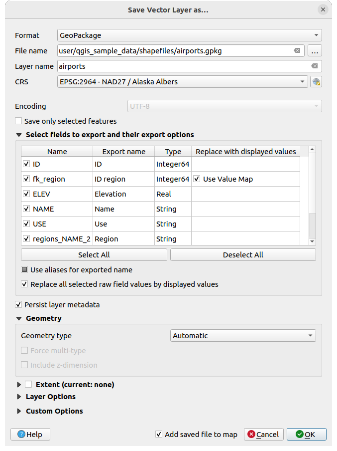
Fig. 11.32 Saving as a new vector layer
When saving a vector layer into an existing file, depending on the capabilities of the output format (Geopackage, SpatiaLite, FileGDB…), the user can decide whether to:
overwrite the whole file
overwrite only the target layer (the layer name is configurable)
append features to the existing target layer
append features, add new fields if there are any.
For formats like ESRI Shapefile, MapInfo .tab, feature append is also available.
11.2.2.4. Point Cloud specific parameters
Similar to raster and vector layers, point cloud layers can be saved in a different format and/or reprojected to a different coordinate reference system (CRS). This allows you to export a point cloud layer to vector or point cloud formats. Current supported formats are: Temporary scratch (memory layer), GeoPackage, ESRI Shapefile, DXF and LAS/LAZ point cloud. In addition to the common parameters listed above, exporting point cloud layers includes the following options:
Filter by Polygon Layer: Allows you to filter the point cloud data based on a polygon layer.
Elevation Range: Enables filtering of the point cloud data based on a specified Z range.
Limit number of points: Provides an option to limit the number of points exported from the point cloud layer.
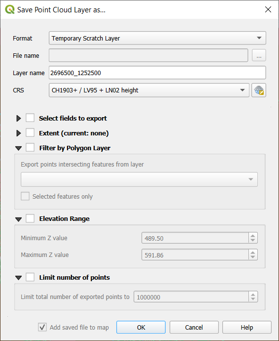
Fig. 11.33 Saving a point cloud layer as a new layer
11.2.3. Creating new DXF files
Besides the Save As… dialog which provides options to export a
single layer to another format, including *.DXF, QGIS provides another
tool to export multiple layers as a single DXF layer. It’s accessible in the
menu.
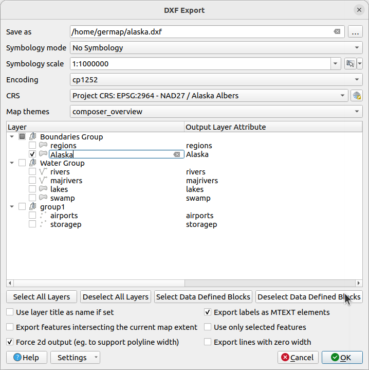
Fig. 11.34 Exporting a project to DXF dialog
In the DXF Export dialog:
Provide the destination file.
Choose the symbology mode and scale (see the OGR Feature Styles note), if applicable.
Select the data Encoding.
Select the CRS to apply: the selected layers will be reprojected to the given CRS.
Select the layers to include in the DXF files either by checking them in the table widget or automatically picking them from an existing map theme. The Select All and Deselect All buttons can help to quickly set the data to export.
For each layer, you can:
Override the output layer name without altering the original project layer. For this, click on the Layer name in the dialog and write the output name to use.
Output layer attribute: Choose whether to export all the features in a single DXF layer or rely on a field whose values are used to split the features into layers in the DXF output. In the latter case, each layer will take its name from the corresponding field value.
Allow data defined symbol blocks:
Maximum number of symbol blocks: creates symbol blocks up to the specified limit, starting with the ones containing the highest number of references. The other symbols are written as they are.
-1means no limitation.
Optionally, you can also choose to:
 Use the layer title as name if set instead of the
layer name itself: the title is taken from the metadata
or server properties of the layer;
Use the layer title as name if set instead of the
layer name itself: the title is taken from the metadata
or server properties of the layer;- Export features intersecting the current map extent;
- Force 2d output (eg. to support polyline width);
- Export label as MTEXT elements or TEXT elements;
- Use only selected features;
- Export lines with zero width: all the lines are exported
with minimal width
0(hairline) if enabled. This helps keep the lines minimal in the file regardless of the zoom level, and can be handy for doing further CAD-editing with the exported dxf, especially if there are many features next to each other on the map.
Note
The precedence for defining the output layer name is as follows:
The field value from Output layer attribute
The overridden name in Layer column
The Use the layer title as name if set option
The layer name
Current settings defined in the DXF Export dialog may be stored in an XML file for reusing them in other sessions. For this, the Settings combo box has two options: Load Settings from File… and Save Settings to File….
11.2.4. Creating new layers from the clipboard
Features that are on the clipboard can be pasted into a new layer. To do this, Select some features, copy them to the clipboard, and then paste them into a new layer using and choosing:
New Vector Layer…: the Save vector layer as… dialog appears (see Creating new layers from an existing layer for parameters)
or Temporary Scratch Layer…: you need to provide a name for the layer
A new layer, filled with selected features and their attributes is created (and added to map canvas).
Note
Creating layers from the clipboard is possible with features selected and copied within QGIS as well as features from another application, as long as their geometries are defined using well-known text (WKT).
11.2.5. Creating SQL Query Layers
Beside loading an entire layer in a project or creating new layers from scratch
or pasted features, you can also load layers generated on the fly from other layer(s).
They are the result of a more or less advanced filter using SQL language,
applied to stored layers regardless of their data provider
or their availability in the active project.
This means that temporary layers are not compatible with this feature.
Depending on the provider, one or more layers can be used to write the query.
The generated layer remains dependent on the layer(s) involved in the query
and is loaded with the  Filter icon next to it.
This feature is accessible:
From the Browser panel, right-click on a supported data (plain layer, database connection, schema or table) and select Execute SQL… entry in the contextual menu.
From the Layers panel, select a loaded layer, right-click and select Execute SQL… entry in the contextual menu.
This opens a window with a central text box widget where you can write SQL queries.
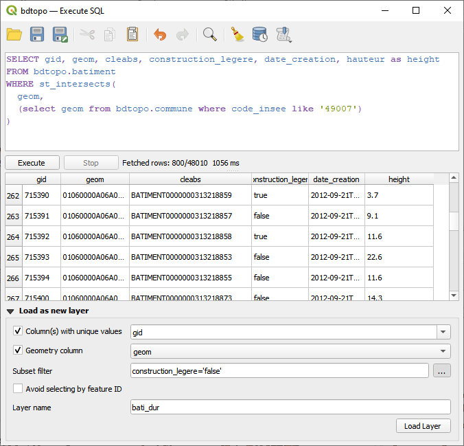
Fig. 11.35 Executing SQL queries in the Execute SQL window
At the top of the dialog, a toolbar provides a set of tools to create, store and manipulate your queries:
 Open Queries…: fills the text editor widget
with contents from an existing
Open Queries…: fills the text editor widget
with contents from an existing .sqlfile Save Queries… and
  Save Queries as…
help you store the written query to a
Save Queries as…
help you store the written query to a .sqlfileStatements of the query can be adjusted using the
 Cut,
Cut,
 Copy and
  Paste buttons.
Likewise, you can
Paste buttons.
Likewise, you can  Undo or
  Redo your changes.
The
 Find & Replace enables, at the bottom of the dialog,
a widget allowing to look for a particular string in your SQL code.
The search can be case sensitive, affect partial or whole word,
rely on a regular expression.
It is then possible to navigate through the found strings, replacing them
one by one or all in a row.
Find & Replace enables, at the bottom of the dialog,
a widget allowing to look for a particular string in your SQL code.
The search can be case sensitive, affect partial or whole word,
rely on a regular expression.
It is then possible to navigate through the found strings, replacing them
one by one or all in a row.Use
 Clear SQL Editor to wipe the text editor.
The
 History button opens a dialog storing previously
run queries. More at Query History.
History button opens a dialog storing previously
run queries. More at Query History.As previously mentioned, queries can be saved as an
.sqlfile stored on disk. Using the Store Current Query button, they can also be stored:
In the active User Profile, in the associated
QGIS4.inifile, thus accessible in subsequent projectsor as part of the Current Project.
Clicking an entry from the stored queries drop-down menu inserts that query in the expression being written. The stored entry can also be deleted, from the drop-down menu.
11.2.5.1. Running and loading queries as layer
In the central part of the Execute SQL dialog, you build your query using the SQL syntax supported by the underlying provider (e.g., OGR, GeoPackage, PostgreSQL).
By default, if opened from a layer entry, a sample SQL query is provided. Editing tools to select, cut, copy, paste, undo and redo are available as well from the contextual menu.
Tip
Finding the right SQL syntax for your dataset
To find the appropriate SQL dialect for your dataset, press the … button next to the Subset filter option in the bottom part of the dialog.
When ready, pressing the Execute button below the text area will run the query. It is possible to highlight a portion of the SQL to only execute that portion when pressing Ctrl+R or clicking the Execute selection button. Use the Stop button to abort the execution.
A successful query execution will display a table at the bottom of the dialog with returned features. You can select specific cells in the result set. Use the Ctrl+C shortcut to copy the selected cells to the clipboard. The copied data is available as a formatted table. This allows you to paste the data into other applications, such as spreadsheet where it will show up as a table.
The returned table can be loaded in QGIS expanding the Load as new layer group and configuring parameters (their availability depends on the layer provider):
Column(s) with unique values to indicate primary key of the data,
Geometry column: check the box to load the layer as a spatial one, and indicate the geometry field name
Subset filter: allows to filter the results using a
WHEREclause. It can be written in the text box, or built using the Query builder after you pressed …. Make sure to use fields that are available in the SQL layer.Avoid selecting by feature ID
Layer name in the project
At any time, in the Layers panel, you can adjust the output layer by right-clicking and selecting Update SQL expression…. The Update SQL dialog opens, prefilled with the applied query that you can edit as you wish. Once ready, press Update layer and the layer will be modified in-place.
11.2.5.2. Query History
The Query History dialog displays all the previously run queries,
sorted by date and data provider type.
It is accessible from the Query History… menu,
or pressing the History button from the Execute SQL dialog.
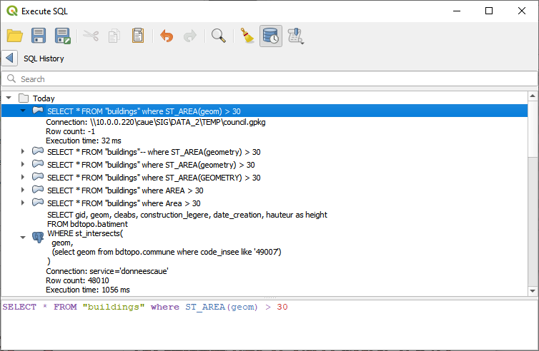
Fig. 11.36 History of the executed SQL queries
At the top of the dialog, a search box can be used to filter out the queries. The search is done through every strings displayed in the query history. If the dialog is opened from within the Execute SQL dialog, the search box is preceded by the Execute SQL toolbar.
Below, collapsible and sorted date entries list their related queries. Each query is identifiable by its SQL command, and when expanded, reveals:
The Connection: the source of the data the query is based on
The Row count: number of returned features
The Execution time
Hover over an entry and a tooltip displays the full query. Likewise, selecting an entry also displayed it in the bottom part of the dialog. You can interact with the text, copying all or part of it.
Double-click the SQL command entry and the Execute SQL dialog opens, filled with the clicked query. Any query being written is overwritten. Right-click the SQL command entry and you can either:
Load SQL Command…, loads the target command into the Execute SQL dialog, replacing any existing query. It is the same as double clicking the entry.
Copy SQL Command and paste it wherever you want.
11.2.6. Creating virtual layers
A virtual layer is a special kind of vector layer. It allows you to define a layer as the result of an SQL query involving any number of other vector layers that QGIS is able to open. Virtual layers do not carry data by themselves and can be seen as views.
To create a virtual layer, open the virtual layer creation dialog by:
choosing the
 Add/Edit Virtual Layer entry
in the menu;
Add/Edit Virtual Layer entry
in the menu;enabling the
Add Virtual Layer tab in the
Data Source Manager dialog;or using the DB Manager dialog tree.
The dialog allows you to specify a Layer name and an SQL Query. The query can use the name (or id) of loaded vector layers as tables, as well as their field names as columns.
For example, if you have a layer called airports, you can create a new
virtual layer called public_airports with an SQL query like:
SELECT *
FROM airports
WHERE USE = "Civilian/Public"
The SQL query will be executed, regardless of the underlying provider of the
airports layer, even if this provider does not directly support SQL
queries.
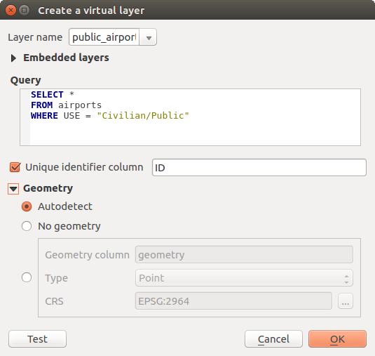
Fig. 11.37 Create virtual layers dialog
Joins and complex queries can also be created, for example, to join airports and country information:
SELECT airports.*, country.population
FROM airports
JOIN country
ON airports.country = country.name
Note
It’s also possible to create virtual layers using the SQL window of DB Manager Plugin.
11.2.6.1. Embedding layers for use in queries
Besides the vector layers available in the map canvas, the user can add layers to the Embedded layers list, which can be used in queries without the need to have them showing in the map canvas or Layers panel.
To embed a layer, click Add and provide the Local name, Provider, Encoding and the path to the Source.
The Import button allows adding layers in the map canvas into the Embedded layers list. Those layers can then be removed from the Layers panel without breaking existent queries.
11.2.6.2. Supported query language
The underlying engine uses SQLite and SpatiaLite to operate.
It means you can use all of the SQL your local installation of SQLite understands.
Functions from SQLite and spatial functions from SpatiaLite can also be used in a virtual layer query. For instance, creating a point layer out of an attribute-only layer can be done with a query similar to:
SELECT id, MakePoint(x, y, 4326) as geometry
FROM coordinates
Functions of QGIS expressions can also be used in a virtual layer query.
To refer the geometry column of a layer, use the name geometry.
Contrary to a pure SQL query, all the fields of a virtual layer query must
be named. Don’t forget to use the as keyword to name your columns if they
are the result of a computation or a function call.
11.2.6.3. Performance issues
With default parameters, the virtual layer engine will try its best to detect the type of the different columns of the query, including the type of the geometry column if one is present.
This is done by introspecting the query when possible or by fetching the first row of the query (LIMIT 1) as a last resort. Fetching the first row of the result just to create the layer may be undesirable for performance reasons.
The creation dialog parameters:
Unique identifier column: specifies a field of the query that represents unique integer values that QGIS can use as row identifiers. By default, an autoincrementing integer value is used. Defining a unique identifier column speeds up the selection of rows by id.
No geometry: forces the virtual layer to ignore any geometry field. The resulting layer is an attribute-only layer.
Geometry Column: specifies the name of the geometry column.
Geometry Type: specifies the type of the geometry.
Geometry CRS: specifies the coordinate reference system of the virtual layer.
11.2.6.4. Special comments
The virtual layer engine tries to determine the type of each column of the query. If it fails, the first row of the query is fetched to determine column types.
The type of a particular column can be specified directly in the query by using some special comments.
The syntax is the following: /*:type*/. It has to be placed just after
the name of a column. type can be either int for integers, real
for floating point numbers or text.
For instance:
SELECT id+1 as nid /*:int*/
FROM table
The type and coordinate reference system of the geometry column can also be set
thanks to special comments with the following syntax /*:gtype:srid*/ where
gtype is the geometry type (point, linestring, polygon,
multipoint, multilinestring or multipolygon) and srid an
integer representing the EPSG code of a coordinate reference system.
11.2.6.5. Use of indexes
When requesting a layer through a virtual layer, the source layer indices will be used in the following ways:
if an
=predicate is used on the primary key column of the layer, the underlying data provider will be asked for a particular id (FilterFid)for any other predicates (
>,<=,!=, etc.) or on a column without a primary key, a request built from an expression will be used to request the underlying vector data provider. It means indexes may be used on database providers if they exist.
A specific syntax exists to handle spatial predicates in requests and triggers
the use of a spatial index: a hidden column named _search_frame_ exists
for each virtual layer. This column can be compared for equality to a bounding
box. Example:
SELECT *
FROM vtab
WHERE _search_frame_=BuildMbr(-2.10,49.38,-1.3,49.99,4326)
Spatial binary predicates like ST_Intersects are sped up significantly
when used in conjunction with this spatial index syntax.