11.2. Visualização de Mapa 3D
3D visualization support is offered through the 3D map view. You can create, manage and open 3D map views via menu:
By clicking on
 you can create a new 3D map view.
A floating and dockable QGIS panel will appear (see The 3D Map View dialog).
It has the same extent and view as the 2D main map canvas
and provides a set of navigation tools to turn the view into 3D.
you can create a new 3D map view.
A floating and dockable QGIS panel will appear (see The 3D Map View dialog).
It has the same extent and view as the 2D main map canvas
and provides a set of navigation tools to turn the view into 3D.By clicking on you get in the 3D Map Views Manager. Here you get the ability to open, duplicate, remove and rename 3D map views.
If you created one or more 3D map views, you see them listed in . You can turn them on and off by clicking on. They will be saved by saving the project, even if they are turned off.
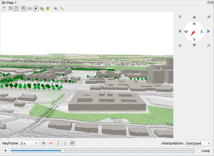
Fig. 11.23 The 3D Map View dialog
The following tools are provided at the top of the 3D map view panel:
 Camera Control: moves the view, keeping the same angle
and direction of the camera
Camera Control: moves the view, keeping the same angle
and direction of the camera Zoom Full: resizes the view to the whole
layers’ extent
Zoom Full: resizes the view to the whole
layers’ extent Toggle On-Screen Notification: shows/hides the
navigation widget (that is meant to ease controlling of the map view)
Toggle On-Screen Notification: shows/hides the
navigation widget (that is meant to ease controlling of the map view) Identify: returns information on the clicked point
of the terrain or the clicked 3D feature(s) – More details at Identificando Feições
Identify: returns information on the clicked point
of the terrain or the clicked 3D feature(s) – More details at Identificando Feições Measurement Line: measures the horizontal distance between points
 Animations: shows/hides the animation player widget
 Save as Image…: exports the current view to
an image file format
Save as Image…: exports the current view to
an image file format Export 3D Scene: exports the current view as a 3D scene
(
Export 3D Scene: exports the current view as a 3D scene
(.objfile), allowing post-processing in applications like Blender… The terrain and vector features are exported as 3D objects. The export settings, overriding the layers properties or map view configuration, include:Scene name and destination Folder
Terrain resolution
Terrain texture resolution
Model scale
 Suavizar bordas
- Export normals
- Exportar texturas
 Set View Theme: Allows you to select the set of layers to
display in the map view from predefined map themes.
Set View Theme: Allows you to select the set of layers to
display in the map view from predefined map themes.The
 Options menu provides shortcuts to:
Add visual effects to the 3D rendering, such as showing shadows, eye dome lighting or ambient occlusion
Synchronize the views (2D map view follows 3D camera and/or 3D camera follows 2D Map view)
Show visible camera area in 2D map view
- Configure the 3D map view settings.
 Dock 3D Map View: switch from docked widget to top level window
11.2.1. Scene Configuration
The 3D map view opens with some default settings you can customize.
To do so, expand the Options menu at the top of
the 3D canvas panel and press the button
to open the 3D configuration window.
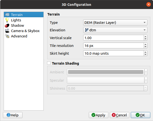
Fig. 11.24 The 3D Map Configuration dialog
In the 3D Configuration window there are various options to fine-tune the 3D scene:
11.2.1.1. Terreno
Terrain: Before diving into the details, it is worth noting that the terrain in a 3D view is represented by a hierarchy of terrain tiles and as the camera moves closer to the terrain, existing tiles that do not have sufficient details are replaced by smaller tiles with more details. Each tile has mesh geometry derived from the elevation raster layer and texture from 2D map layers.
The elevation terrain Type can be:
a Flat terrain
a loaded DEM (Raster Layer)
an Online service, loading elevation tiles produced by Mapzen tools – more details at https://registry.opendata.aws/terrain-tiles/
a loaded Mesh dataset
Elevation: Raster or mesh layer to be used for generation of the terrain. The raster layer must contain a band that represents elevation. For a mesh layer, the Z values of the vertices are used.
Vertical scale: Scale factor for vertical axis. Increasing the scale will exaggerate the height of the landforms.
Tile resolution: How many samples from the terrain raster layer to use for each tile. A value of 16px means that the geometry of each tile will consist of 16x16 elevation samples. Higher numbers create more detailed terrain tiles at the expense of increased rendering complexity.
Skirt height: Sometimes it is possible to see small cracks between tiles of the terrain. Raising this value will add vertical walls (“skirts”) around terrain tiles to hide the cracks.
Offset: moves the terrain up or down, e.g. to adjust its elevation with respect to the ground level of other objects in the scene.
Isso pode ser útil quando há uma discrepância entre a altura do terreno e a altura das camadas em sua cena (por exemplo, nuvens de pontos que usam apenas uma altura vertical relativa). Nesse caso, ajustar a elevação do terreno manualmente para coincidir com a elevação dos objetos em sua cena pode melhorar a experiência de navegação.
When a mesh layer is used as terrain, you can configure the Triangles settings (wireframe display, smooth triangles, level of detail) and the Rendering colors settings (as a uniform color or color ramp based). More details in the Mesh layer 3D properties section.
 Terrain shading: Permite a você escolher como o terreno deveria ser renderizado:
Shading disabled - terrain color is determined only from map texture
Shading enabled - terrain color is determined using Phong’s shading model, taking into account map texture, the terrain normal vector, scene light(s) and the terrain material’s Ambient and Specular colors and Shininess
11.2.1.2. Luzes
From the Lights tab, press the  menu to add
up to eight Point lights: emits light in all directions, like a sphere of light filling an area. Objects closer to the light will be brighter, and objects further away will be darker. A point light has a set position (X, Y and Z), a Color, an Intensity and an Attenuation
up to four Directional lights: mimics the lighting that you would get from a giant flash light very far away from your objects, always centered and that never dies off (e.g. the sun). It emits parallel light rays in a single direction but the light reaches out into infinity. A directional light can be rotated given an Azimuth, have an Altitude, a Color and an Intensity.
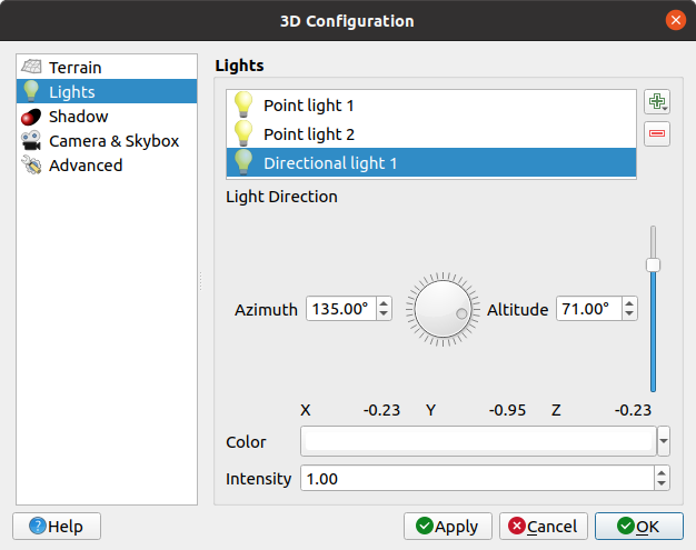
Fig. 11.25 The 3D Map Lights Configuration dialog
11.2.1.3. Sombra
Check Show shadows to display shadows within your scene,
given:
a Directional light
a Shadow rendering maximum distance: to avoid rendering shadow of too distant objects, particularly when the camera looks up along the horizon
a Shadow bias: to avoid self-shadowing effects that could make some areas darker than others, due to differences between map sizes. The lower the better
a Shadow map resolution: to make shadows look sharper. It may result in less performance if the resolution parameter is too high.
11.2.1.4. Camera & Skybox
In this tab, you can control different parameters like camera, 3D axis, navigation synchronization and skybox.
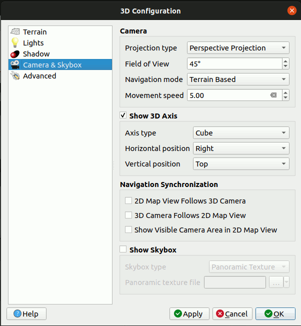
Fig. 11.26 The 3D Map Camera Configuration dialog
The Camera parameter group overrides some default camera settings made in the dialog.
Check
Show 3D Axis to enable 3D axis tool. This parameter
group allows to set the axis type and its position.With the Coordinate Reference System type an orthogonal axis will be represented.
With the Cube type, a 3D cube will be represented. The cube faces can be used to change the camera view: for example, click on the north face to set the camera to see from the north.
Dica
Right-click the 3D axis to quickly set its position and type, and the camera view.
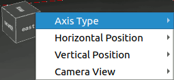
Fig. 11.27 The 3D Axis context menu
The Navigation Synchronization parameter group adds options to synchronize 2D view with 3D camera position or 3D camera position with 2D view or bi directional synchronization. The last option displays the extent visible from the 3D camera over the 2D map view.
Check
Show skybox to enable skybox rendering
in the scene. The skybox type can be:Panoramic texture, with a single file providing sight on 360°
Distinct faces, with a texture file for each of the six sides of a box containing the scene
Texture image files of the skybox can be files on the disk, remote URLs or embedded in the project (more details).
11.2.1.5. Avançado
Map tile resolution: Width and height of the 2D map images used as textures for the terrain tiles. 256px means that each tile will be rendered into an image of 256x256 pixels. Higher numbers create more detailed terrain tiles at the expense of increased rendering complexity.
Max. screen error: Determines the threshold for swapping terrain tiles with more detailed ones (and vice versa) - i.e. how soon the 3D view will use higher quality tiles. Lower numbers mean more details in the scene at the expense of increased rendering complexity.
Max. ground error: The resolution of the terrain tiles at which dividing tiles into more detailed ones will stop (splitting them would not introduce any extra detail anyway). This value limits the depth of the hierarchy of tiles: lower values make the hierarchy deep, increasing rendering complexity.
Zoom levels: Shows the number of zoom levels (depends on the map tile resolution and max. ground error).
- Show labels: Ativa/desativa os rótulos de mapa
- Show map tile info: Include border and tile
numbers for the terrain tiles (useful for troubleshooting terrain issues)
- Show bounding boxes: Show 3D bounding boxes
of the terrain tiles (useful for troubleshooting terrain issues)
- Show camera’s view center
- Show camera’s rotation center
- Show light sources: shows a sphere at light source origins,
allowing easier repositioning and placement of light sources relative to the scene contents
- Show frames per second (FPS)
- Show debug overlay: visual overlay which displays
some useful debugging and profiling information.
This allows in particular to quickly see the frame graph and the scene graph.
- Show Eye Dome Lighting (EDL):
a post processing effect which enhances depth perception.
Each pixel’s depth (distance off the camera) is compared to its neighboring pixels’ depth
and gets highlighted according to that depth difference, making the edges stand out.
Affects the whole scene and can be combined with Screen Space Ambient Occlusion.
Following parameters can be controlled:
Lighting strength: increases the contrast, allowing for better depth perception
Lighting distance: represents the distance of the used pixels off the center pixel and has the effect of making edges thicker.
Add screen-space
Ambient Occlusion (SSAO):
a post processing effect which also enhances depth perception
by applying a darker shading to areas which are less exposed to ambient lighting.
Affects the whole scene and can be combined with Eye dome Lighting.
Following parameters can be controlled:Radius: how far we will reach to calculate ambient occlusion
Intensity: how strong the effect should be (higher values make things darker)
Occlusion threshold: how many neighboring points need to be occluded for the effect to appear (lower values than 50% will make the output darker, but possibly providing greater range of occlusion)
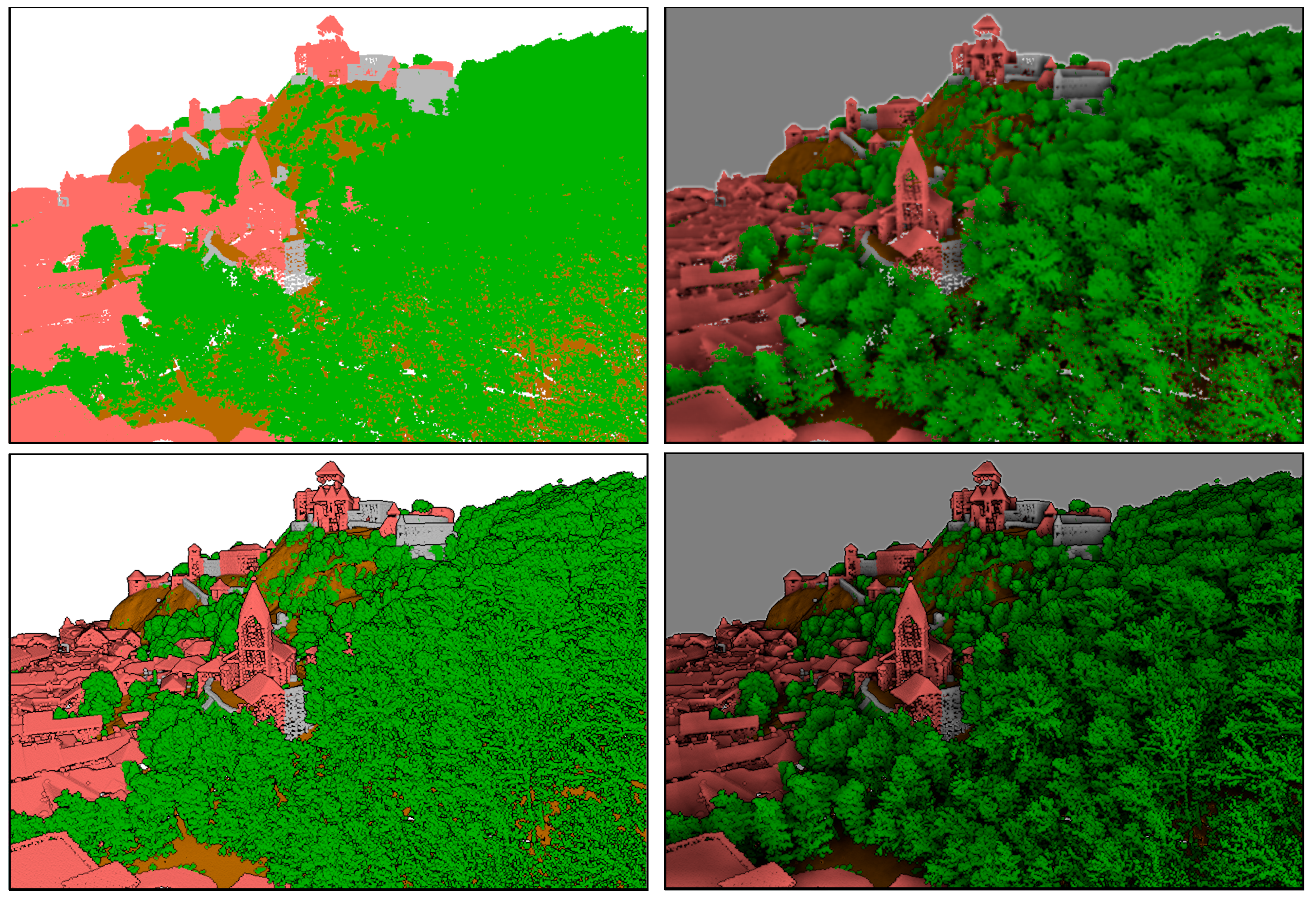
Fig. 11.28 Rendering Point clouds in 3D map using Eye Dome Lighting (EDL) and/or Screen-Space Ambient Occlusion (SSAO)
From top, left to right: No effect – SSAO only – EDL only – SSAO and EDL
- Debug Shadow Map: renders the scene as a red-black image
from the point of view of the light used for shadows (for troubleshooting).
The widget is set with a proportional Size to the 3D map view’s,
and docked in a Corner.
- Debug Depth Map: renders the scene’s depth map as an image
with nearer pixels being darker (for troubleshooting).
The widget is set with a proportional Size to the 3D map view’s,
and docked in a Corner.
11.2.2. Opções de navegação
Para explorar a visualização do mapa em 3D:
Tilt the terrain (rotating it around a horizontal axis that goes through the center of the window)
Press the
 Tilt up and
  Tilt down tools
Press Shift and use the up/down keys
Arraste o mouse para frente/para trás com o botão central do mouse pressionado
Pressione Shift e arraste o mouse para frente/para trás com o botão esquerdo do mouse pressionado
Rotacionar o terreno (em torno de um eixo vertical que atravessa o centro da janela)
Turn the compass of the navigation widget to the watching direction
Pressione Shift e use as teclas esquerda/direita
Arraste o mouse para a direita/esquerda com o botão central do mouse pressionado
Pressione Shift e arraste o mouse para a direita/esquerda com o botão esquerdo do mouse pressionado
Mudar a posição da câmera (e o centro de visão), movendo-a em um plano horizontal
Drag the mouse with the left mouse button pressed, and the
Camera control button enabledPress the directional arrows of the navigation widget
Use as teclas para cima/para baixo/esquerda/direita para mover a câmera para frente, para trás, direita e esquerda, respectivamente
Change the camera altitude: press the Page Up/Page Down keys
Alterar a orientação da câmera (a câmera é mantida em sua posição, mas o ponto central da visão se move)
Press Ctrl and use the arrow keys to turn the camera up, down, left and right
Press Ctrl and drag the mouse with the left mouse button pressed
Aumentar e diminuir o zoom
Press the corresponding
 Zoom In and
  Zoom Out tools of the navigation widget
Scroll the mouse wheel (keep Ctrl pressed results in finer zooms)
Drag the mouse with the right mouse button pressed to zoom in (drag down) and out (drag up)
Para redefinir a visualização da câmera, clique no botão :sup:`Zoom completo’ na parte superior do painel de tela 3D.
11.2.3. Criar uma animação
Uma animação é baseada em um conjunto de quadros-chave - posições da câmera em momentos específicos. Para criar uma animação:
Toggle on the
Animations tool, displaying the animation player
widgetClick the
Add keyframe button and enter a Keyframe
time in seconds. The Keyframe combo box now displays the time set.Usando as ferramentas de navegação, mova a câmera para a posição para associar ao tempo atual do quadro-chave.
Repita as etapas anteriores para adicionar quantos quadros-chave (com tempo e posição) forem necessários.
Click the
button to preview the animation. QGIS will generate scenes using
the camera positions/rotations at set times, and interpolating them in between
these keyframes. Various Interpolation modes for animations are
available (eg, linear, inQuad, outQuad, inCirc… – more details at
https://doc.qt.io/qt-5/qeasingcurve.html#EasingFunction-typedef).The animation can also be previewed by moving the time slider. Keeping the Loop box checked will repeatedly run the animation while clicking
stops a running animation.
Click  Export animation frames to generate a series of images
representing the scene. Other than the filename Template and the
Output directory, you can set the number of Frames per
second, the Output width and Output height.
Export animation frames to generate a series of images
representing the scene. Other than the filename Template and the
Output directory, you can set the number of Frames per
second, the Output width and Output height.
11.2.4. Camadas vetoriais 3D
Uma camada vetorial com valores de elevação pode ser mostrada no mapa 3D, marcando Ativar renderizador 3D na seção Vista 3D das propriedades da camada vetorial. Há várias opções disponíveis para controlar a renderização da camada vetorial 3D.