Wichtig
Übersetzen ist eine Gemeinschaftsleistung Sie können mitmachen. Diese Seite ist aktuell zu 96.78% übersetzt.
7.1. 2D Kartenansichten
Die 2D-Kartenansicht, meist nur Kartenansicht genannt, ist der zentrale Ort, an dem Karten dargestellt werden. QGIS öffnet standardmäßig mit einer einzigen Kartenansicht (Hauptkarte), die Layer in 2D zeigt und eng mit dem Layer Bedienfeld verbunden ist. In diesem Bedienfeld können die Einstellungen gemacht werden (Symbologie, Beschriftung, Sichtbarkeit …), die Sie auf die geladenen Layer anwenden möchten.
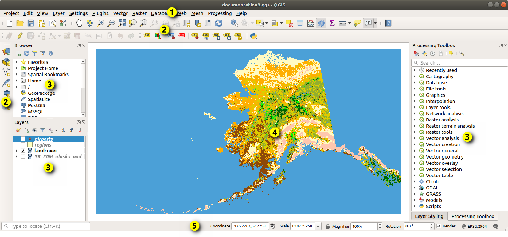
Abb. 7.1 Die QGIS Oberfläche
7.1.1. Funktionen des Kartenfensters
Wenn Sie einen Layer hinzufügen (s.a. Öffnen von Daten), sucht QGIS automatisch nach dem Koordinatenbezugssystem (KBS) des Layers. Wenn für das Projekt ein anderes KBS eingestellt ist, dann wird die Darstellung des Layers „on-the-fly“ in dieses KBS überführt (siehe Koordinatenbezugssysteme für Projekte). Wenn Sie mit einem leeren QGIS-Projekt beginnenund wird die Kartenansicht auf die Ausdehnung des/der zuerst hinzugefügten Layer gezoomt. Wenn bereits Layer im Projekt vorhanden sind, wird keine Größenänderung der Kartenansicht durchgeführt, so dass nur Features sichtbar sind, die innerhalb der aktuellen Kartenansicht liegen.
Wenn Sie in die Kartenansicht klicken, können Sie mit dieser interagieren, indem Sie den Ausschnitt der Karte verschieben oder hinein- oder heraus-zoomen. Spezielle Werkzeuge sind in der Navigations-Werkzeugleiste und im Menü zu finden, für viele davon existieren Tastenkombinationen.
Werkzeug |
Funktion |
|---|---|
|
|
|
|
|
|
|
Verschiebt die Karte auf die ausgewählten Objekte aller ausgewählten Layer im Layer Bedienfeld |
|
Zoom auf die ausgewählten Objekte aller ausgewählten Layer im Layer Bedienfeld (Ist auch im Layer-Kontextmenü verfügbar) |
|
Zoomt auf die Ausdehnung aller ausgewählten Layer im Layer Bedienfeld (Ist auch im Layer-Kontextmenü verfügbar) |
|
Zoom auf den Umfang aller Layer im Projekt oder auf die gesetzte Projekt-Ausdehnung |
|
Zoomt die Karte auf die vorherige Ausdehnung |
|
Zoomt die Karte auf die nächste Ausdehnung |
|
Zoomt die Karte auf einen Maßstab, bei der ein Pixel des aktiven Raster-Layers einem Bildschirmpixel entspricht (Ist auch im Layer-Kontextmenü verfügbar) |
Maus |
|
Tastatur |
|


Mit einem rechten Mausklick in die Karte können Sie die Koordinaten des angeklickten Punktes kopieren ( Koordinaten kopieren), entweder im KBS der Karte, in WGS84-Koordinaten oder Sie können ein anderes KBS auswählen. Die kopierten Informationen stehen dann in der Zwischenablage zur Verfügung und können über „Einfügen“ in einer anderen Anwendung verwendet werden.
7.1.2. Steuerung der Kartendarstellung
Standardmäßig werden von QGIS alle sichtbaren Layer dargestellt, wenn die Kartenansicht aktualisiert wird. Die folgenden Ereignissen führen zu einer Aktualisierung der Kartenansicht:
Ändern der Sichtbarkeit eines Layers
Ändern der Symbologie eines sichtbaren Layers
Einen Layer hinzufügen
Kartenausschnitt verschieben oder Zoomen
Ändern der Größe des QGIS Fensters
QGIS ermöglicht es Ihnen, die Darstellung auf verschiedene Weise zu steuern:
Auf Projekt-Ebene
Auf Layer-Ebene, z. B. unter Verwendung der Maßstabsabhängigen Sichtbarkeit
Mit speziellen Werkzeugen in der grafischen Benutzeroberfläche
Um das Zeichnen der Karte zu stoppen, drücken Sie die Esc Taste. Dadurch wird die Aktualisierung der Kartenansicht angehalten und die Karte bleibt so gezeichnet, wie sie es zum Zeitpunkt des Abbruchs war. Nach dem Drücken der Esc Taste kann es jedoch einige Zeit dauern, bis der Prozess tatsächlich abgebrochen wird.
Um eine Aktualisierung der Kartenansicht zu unterdrücken, können Sie das Kontrollkästchen Zeichnen im rechten Bereich der Statusleiste unten deaktivieren. Die Kartenansicht wird dann nicht aktualisiert, wenn eins der oben genannten Ereignisse eintritt. Dies können Sie z.B. für eine der folgenden Situationen nutzen:
Hinzufügen von mehreren Layern und dabei die Darstellung anpassen, bevor sie das erste Mal gezeichnet werden
Hinzufügen eines oder mehrerer großer Layer und Einstellen der Skalierungsabhängigkeit
Hinzufügen eines oder mehrerer großer Layer und Zoomen auf einen bestimmten Ausschnitt
eine beliebige Kombination der oben genannten Punkte
Wenn Sie das  Zeichnen Kontrollkästchen wieder aktivieren, findet unmittelbar eine Aktualisierung der Kartenansicht statt.
7.1.3. Zeitabhängige Darstellung in der Kartenansicht
In QGIS können Layer zeitlich gesteuert dargestellt werden, d.h. die Kartenansicht wird in Abhängigkeit von der Zeit verändert. Um dies durchführen zu können, benötigen Sie:
Einen oder mehrere Layer, für den zeitlich-dynamische Eigenschaften festgelegt wurden. QGIS unterstützt die zeitliche Steuerung für verschiedene Layer-Typen mit unterschiedlichen Einstellungen. Diese unterscheiden sich in erster Linie bei der Einstellung des Zeitintervalls, in dem der Layer angezeigt werden kann:
Raster Layer: es wird nur festgelegt, ob der Layer angezeigt werden soll oder nicht
WMTS Layer: es wird festgelegt, ob die Daten auf der Grundlage eines statischen Zeitbereichs oder nach einem dynamischen Zeitbereich dargestellt werden sollen
Vektor-Layer: die Objekte können über Zeitangaben gesteuert werden, die in der Attributtabelle enthalten sind
Netz-Layer: die Werte der aktiven Datensatzgruppen können dynamisch anzeigt
Wenn zeitlich-dynamische Eigenschaften für einen Layer aktiviert sind, ist neben dem Layer im Layer Bedienfeld ein Symbol
 sichtbar, um anzuzeigen, dass der Layer zeitgesteuert ist. Klicken Sie auf das Symbol, um die zeitlichen Einstellungen zu ändern.
Aktivierung der zeitlichen Steuerung der Kartenansicht mit dem Zeitsteuerung Bedienfeld. Das Bedienfeld selber kann angezeigt werden über
das Symbol
 Zeitsteuerungsfenster in der Kartennavigationswerkzeugleiste
über das Menü
über das Menü
7.1.3.1. Das Zeitsteuerung-Bedienfeld
Das Zeitsteuerung Bedienfeld bietet die folgenden Einstellungsmöglichkeiten:
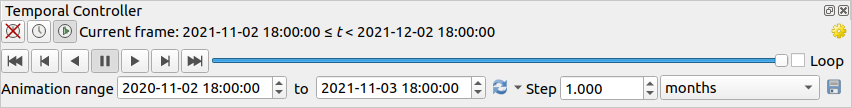
Abb. 7.2 Zeitsteuerung-Bedienfeld im Navigationsmodus
 Zeitliche Navigation abschalten: alle zeitlichen Einstellungen sind deaktiviert und die aktiven Layer werden wie gewohnt angezeigt
 Zeit-Navigation in festem Bereich: ein Zeitbereich wird festgelegt und nur Layer oder Objekte, deren Zeitbereich sich mit diesem überschneidet, werden auf der Karte angezeigt
 Animierte Zeitnavigation: ein Zeitbereich und eine Schrittlänge innerhalb dieses Zeitbereichs werden festgelegt und es werden nur Layer oder Objekte angezeigt, die sich innerhalb des jeweiligen Schrittes befinden
 Animierter Film: Für die Animation wird eine Gesamtzahl von Bildern festgelegt, wobei die Karteneinstellungen bei jedem Schritt weitergeschaltet werden und der Fortschritt Bild für Bild ohne zeitbasierte Filterung der Daten angezeigt wird.
 Einstellungen für die Steuerung der Animation:
Bildrate: Anzahl der Bilder, die pro Sekunde angezeigt werden
 Kumulativer Bereich: alle Animationsbilder haben die gleiche Startzeit, aber unterschiedliche Enddaten und -zeiten. Dies ist nützlich, wenn Sie Daten in Ihrer zeitlichen Visualisierung akkumulieren möchten, anstatt ein „bewegliches Zeitfenster“ über die Daten laufen zu lassen.
7.1.3.2. Animieren einer zeitlichen Navigation
Eine zeitliche Animation besteht aus einer Reihe von Bildern aller zeitlich aktiven Layer zu einem bestimmten Zeitpunkten. So erstellen Sie eine zeitliche Animation:
Schalten Sie auf
Animierte Zeitnavigation um, sodass die Bedienelemente des Players anzeigt werdenGeben Sie den Animationsbereich ein, der berücksichtigt werden soll . Mit der
 Schaltfläche kann dieser wie folgt automatisch definiert werden:
Auf ganzen Bereich setzen legt den Animationsbereich so fest, dass die Zeiträume aller zeitlich aktivierten Layer berücksichtigt werden
Auf Projektbereich voreinstellen legt den Animationsbereich so fest, wie er in den Projekteigenschaften definiert ist
Bereich eines einzelnen Layers setzen legt den Bereich auf die Spanne der Werte eines einzelnen Layers fest
Mit der Angabe unter Schritt wird die Zeitspanne in einzelne Intervalle unterteilt. Es werden verschiedene Einheiten unterstützt z. B.
SekundenoderJahrhunderte. Als Einheit ist auch die OptionQuellzeitstempelmöglich: Wenn dies ausgewählt ist, bewirkt es, dass die zeitliche Navigation zwischen unterschiedlichen Zeitbereichen der Layer wechselt. Dies ist nützlich, wenn Layer verwendet werden, deren Daten nicht in regelmäßigen Abständen vorliegen. Dies kann z. B. bei einem WMS-T-Dienst der Falls sein, der Bilder bereitstellt, die unregelmäßige Zeitpunkte wiedergeben. Diese Option ermöglicht es ihnen, mit einem Schritt einfach in den Zeitbereich zu wechseln, in dem das nächste Bild verfügbar ist.Klicken Sie auf die Schaltfläche
 , um eine Vorschau der Animation zu erhalten. QGIS erzeugt eine Serie von Bildern mit den Layern und/oder Objekten, die der eingestellten Zeit entsprechen. Die Anzeige der Layer oder Objekte hängt dabei davon ab, ob deren Zeitstempel innerhalb des jeweiligen Zeitintervalls liegen.
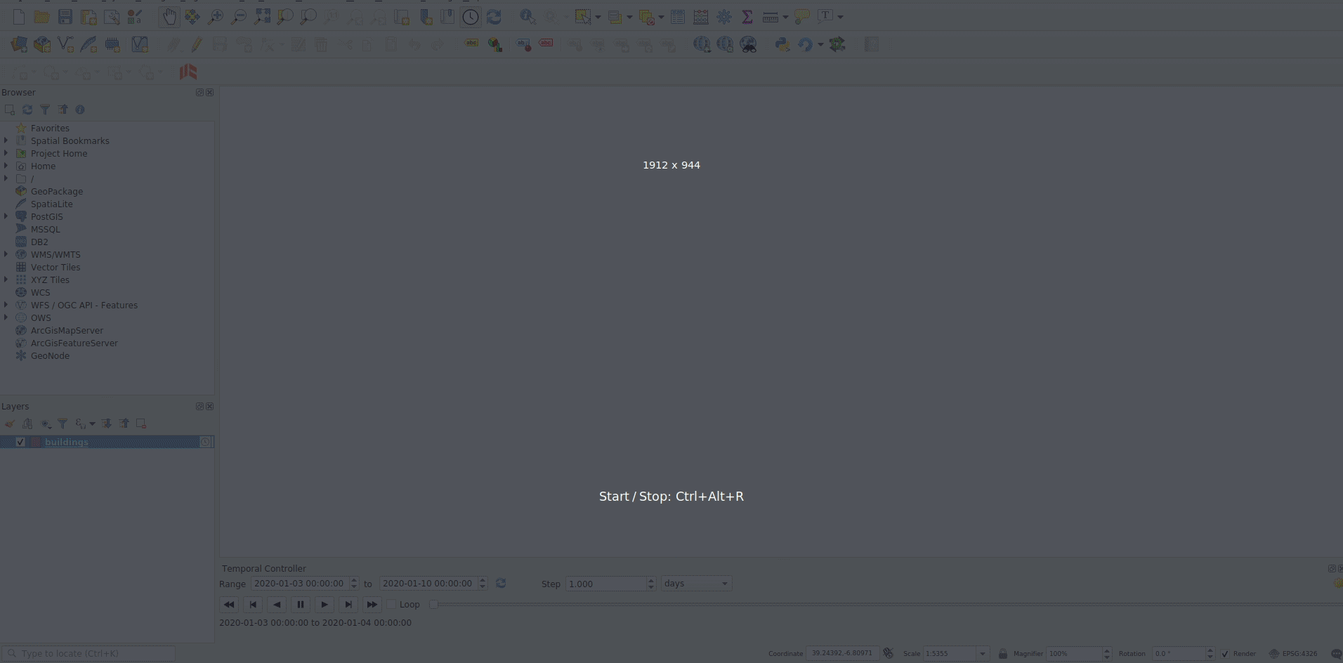
Abb. 7.3 Zeitliche Navigation durch einen Layer
Die Animation kann auch durch Verschieben des Zeitreglers in der Vorschau angezeigt werden. Wenn Sie das Kontrollkästchen
Schleife markieren, wird die Animation wiederholt ausgeführt, während ein Klick auf eine laufende Animation stoppt. Ein vollständiger Satz der üblichen Player-Schaltflächen ist verfügbar.Durch horizontales Scrollen mit dem Mausrad (sofern von Ihrer Maus unterstützt), während sich der Cursor innerhalb der Kartenansicht befindet, können Sie auch den Schieberegler für die zeitliche Navigation vorwärts und rückwärts verschieben (“scrubben”).
Klicken Sie auf die Schaltfläche
 Animation exportieren, wenn Sie die Serie von Bildern exportieren wollen. Diese kann dann z. B. in einem Videoeditor zusammengefügt werden:
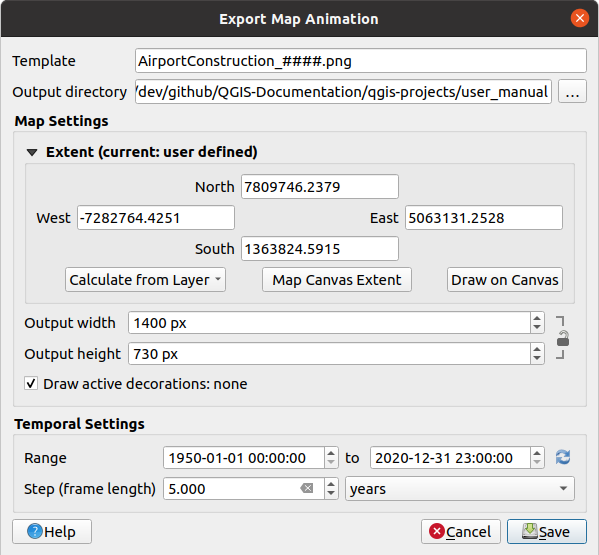
Abb. 7.4 Fenster zum Exportieren von Bildern einer Animation
in der Vorlage für den Dateinamen werden die Platzhalter
####durch fortlaufende Bildnummern ersetztdas Ausgabeverzeichnis muss angegeben werden
unter Karteneinstellungen können Sie:
die räumliche Ausdehnung festlegen
die Auflösung der Bilder mit Ausgabebreite und Ausgabehöhe festlegen
Aktive Dekorationen anzeigen aktivieren/deaktivieren: damit legen Sie fest, ob Dekorationen in den Ausgabe-Bildern dargestellt sein sollen
unter Zeiteinstellungen können Sie folgende Parameter noch verändern:
den Bereich für die Zeitspanne der Animation
die Schrittweite (Einzelbildlänge) in der gewünschten Einheit
7.1.4. Das Bedienelement für die Höhensteuerung
Mit dem  Höhensteuerung-Bedienelement können Sie Höhenwerte (Z-Werte) in 2D-Karten verarbeiten. Diese Option unterstützt derzeit Punktwolken-Layer und Raster-DEMs.
Aktivieren Sie das Höhensteuerung-Bedienelement in der Kartenansicht, indem Sie im Menü Ansicht auf Datenfiltrierung klicken und dann Höhensteuerung auswählen. Diese wird darauf hin als Schieberegler auf der linken Seite der Kartenansicht angezeigt. Oberhalb des Schiebereglers befindet sich das Einstellungen-Menü, in dem Sie folgende Optionen haben:
Setzen Sie eine Wert für Fester Größenbereich, um den Höhenbereich auf eine bestimmte Größe festzulegen. Diese Einstellung wird im Projekt gespeichert, sodass die Konsistenz Ihres Höhenfilters gewährleistet ist. Verwenden Sie
Richtung umkehren, um den Schieberegler der Höhensteuerung umzukehren, sodass er sich von hohen Werten unten zu niedrigen Werten oben bewegt.Mit Höhenbereich setzen gelangen Sie zu den Projekt-Eigenschaften, wo Sie auf dem Reiter Geländehöhe spezielle Unter- und Obergrenzen für den Höhenbereich festlegen können.
Mit Höhenfilter abschalten können Sie den Schieberegler aus der Kartenansicht entfernen
7.1.5. Räumliche Lesezeichen
Räumliche Lesezeichen ermöglichen es Ihnen, einen bestimmten Ausschnitt der Karte zu speichern und später dorthin zurückzukehren. Standardmäßig werden Lesezeichen im Benutzerprofil gespeichert (als Benutzer-Lesezeichen), d.h. sie sind in jedem Projekt, das der Benutzer öffnet, verfügbar. Sie können aber auch nur für ein bestimmtes Projekt gespeichert werden (als Projekt-Lesezeichen), wobei sie dann mit in der Projektdatei abgelegt werden. Das kann z. B. hilfreich sein, wenn das Projekt mit anderen Benutzern geteilt wird.
7.1.5.1. Ein Lesezeichen erstellen
Um ein Lesezeichen zu erstellen, gehen Sie wie folgt vor:
Wählen Sie mittels zoomen und schwenken in der Kartenansicht den Ausschnitt aus, für den Sie ein Lesezeichen setzen wollen
Wählen Sie entweder im Menü den Punkt
 aus oder klicken Sie im Browser Bedienfeld mit der rechten Maustaste auf den Eintrag
  Räumliche Lesezeichen und wählen Sie Neues räumliches Lesezeichen… oder drücken Sie Strg+B; jeweils wird das Dialog-Fenster Lesezeichenbearbeitung geöffnet
Abb. 7.5 Der Lesezeichenbearbeitung-Dialog
Geben Sie einen Namen für das Lesezeichen ein
Optional: Sie können einen Gruppennamen eingeben oder eine bestehende Gruppe auswählen, in der verwandte Lesezeichen gespeichert werden sollen
Optional: Sie können den Ausschnitt der Karte, den Sie speichern möchten, mit dem Ausdehnung-Werkzeug noch anpassen; vorausgewählt ist der aktuelle Ausschnitt der Kartenansicht
Optional: Geben Sie eine Drehung der Karte in Grad an
Optional: Geben Sie ein anderes KBS, als das des Projekts an, das für den Ausschnitt verwendet werden soll
Wählen Sie aus, ob das Lesezeichen als Benutzer-Lesezeichen (vorausgewählt) oder als Projekt-Lesezeichen gespeichert werden soll
Drücken Sie Speichern, um das Lesezeichen der Liste hinzuzufügen
Es ist möglich, mehrere Lesezeichen mit demselben Namen zu erstellen.
7.1.5.2. Arbeiten mit Lesezeichen
To use and manage bookmarks, you can either use the Spatial Bookmarks panel or Browser:
Select
or press Ctrl+7 to open the Spatial Bookmark Manager panel.Select
or press Ctrl+Shift+B to show the Spatial Bookmarks entry
in the Browser panel.
Sie können die in der nachfolgenden Tabelle aufgeführten Aktionen ausführen.
Aufgabe |
Räumliche Lesezeichenverwaltung |
Browser |
|---|---|---|
Auf ein Lesezeichen zoomen |
Doppelklicken Sie auf das Lesezeichen oder wählen Sie es aus und drücken Sie die Schaltfläche |
Doppelklicken Sie auf das Lesezeichen oder ziehen Sie es auf die Kartenansicht oder klicken Sie mit der rechten Maustaste darauf und wählen Sie Zum Lesezeichen zoomen |
Lesezeichen löschen |
Wählen Sie das Lesezeichen aus und klicken Sie auf die Schaltfläche |
Klicken Sie mit der rechten Maustaste auf das Lesezeichen und wählen Sie Räumliches Lesezeichen löschen |
Lesezeichen nach XML exportieren |
Klicken Sie auf die Schaltfläche |
Wählen Sie einen oder mehrere Ordner (Benutzer oder Projekt) oder Unterordner (Gruppen) aus, klicken Sie dann mit der rechten Maustaste und wählen Sie |
Lesezeichen aus XML importieren |
Klicken Sie auf die Schaltfläche |
Klicken Sie mit der rechten Maustaste auf den Eintrag Räumliche Lesezeichen oder einen Unterordner (Benutzer oder Projekt) oder eine Gruppe, um festzulegen, wohin die Lesezeichen importiert werden sollen, und wählen Sie dann |
Lesezeichen bearbeiten |
Sie können ein Lesezeichen ändern, indem Sie die Werte in der Tabelle ändern. Sie können den Namen, die Gruppe, die Ausdehnung und ob es im Projekt gespeichert ist oder nicht, bearbeiten. |
Klicken Sie mit der rechten Maustaste auf das gewünschte Lesezeichen und wählen Sie Räumliches Lesezeichen bearbeiten…, wodurch der Lesezeichenbearbeitung Dialog geöffnet wird. Hier können Sie jeden Aspekt des Lesezeichens neu definieren, als ob Sie es zum ersten Mal erstellen würden. Sie können die Lesezeichen auch mittels Drag-and-drop zwischen Ordnern (Benutzer und Projekt) und Unterordnern (Gruppen) verschieben. |


Sie können den Lesezeichenbearbeitung Dialog auch öffnen, indem Sie im Bedienfeld Räumliche Lesezeichenverwaltung mit der rechten Maustaste auf das gewünschte Lesezeichen klicken. Darüber hinaus ist es möglich, zu einem Lesezeichen zu zoomen, indem Sie den Namen des Lesezeichens in das Suchen Feld in der Statusleiste eingeben.
7.1.6. Dekorationen
Unter den Begriff Dekorationen fallen Gitter, Titelbeschriftung, Copyright-Beschriftung, Bild, Nordpfeil, Maßstabsbalken und Layoutausdehnung. Sie werden z.B. verwendet, um den Informationsgehalt einer Karte zu erhöhen oder um sie lesbarer zu machen.
7.1.6.1. Gitter
Die Dekoration  Gitter ermöglicht das Hinzufügen eines Koordinatengitters und von Koordinatenbeschriftungen zur Kartenansicht.
Wählen Sie den Menüpunkt um den Dialog zu öffnen.
Abb. 7.6 Der Gitter Dialog
Markieren Sie das Kontrollkästchen Gitter aktivieren und setzen Sie die Gitterdefinitionen entsprechend Ihren Bedürfnissen:
Gittertyp: die Optionen sind Linie oder Markierung
Das zum Gittertyp gehörende Liniensymbol oder Markierungssymbol, das zur Darstellung der Gittermarken verwendet werden soll
Einen Intervall die X- und die Intervall Y-Achse für den Abstand zwischen den Gittermarkierungen (in Karteneinheiten)
Einen Versatz für X und Y für den Abstand der Gittermarkierungen von der linken, unteren Ecke der Kartenansicht (in Karteneinheiten)
Sie können die Intervall- und Versatz-Parameter festlegen, indem Sie auf die darunter befindlichen Schaltflächen klicken:
Canvas Extents: generates a grid with an interval that is approximately 1/5 of the canvas width
Aktiven Rasterlayer verwendet die Auflösung des aktiven Rasterlayers
Aktivieren Sie
Beschriftung zeichnen, um die Koordinaten der Gittermarkierungen anzeigen zu lassen, wobei Sie folgende Einstellungs-Optionen haben:Beschriftungsausrichtung: legt fest, wie die Beschriftungen relativ zu ihrer Gitterlinie platziert werden sollen. Die Möglichkeiten sind:
Horizontal oder Vertikal, jeweils für alle Beschriftungen
Horizontal und Vertikal, d.h. jede Beschriftung ist parallel zu der Gittermarkierung, auf die sie sich bezieht
Grenzlinienrichtung, d.h. die Beschriftungen folgen der Begrenzung der Kartenansicht und stehen senkrecht zu der jeweiligen Gittermarkierung, auf die sie sich beziehen
Beschriftungsschriftart: Textformatierung, Puffer, Schatten, … unter Verwendung des Schriftauswahl Werkzeugs
Abstand zum Kartenrahmen: Abstand zwischen Beschriftung und den Grenzen der Kartenansicht; hilfreich beim Exportieren der Kartenansicht z.B. in ein Bildformat oder ein PDF, und um zu vermeiden, dass Anmerkungen auf den „Papier“-Grenzen liegen
Koordinatengenauigkeit
Klicken Sie auf Anwenden, um zu überprüfen, ob es wie erwartet aussieht, oder auf OK, wenn Sie zufrieden sind.
7.1.6.2. Titelbeschriftung
Die  Titelbeschriftung ermöglicht es Ihnen, Ihre Karte mit einem Titel zu versehen.
Um eine Titelbeschriftung einzufügen, gehen Sie wie folgt vor:
Wählen Sie den Menüpunkt um den Dialog zu öffnen.
Abb. 7.7 Der Titelbeschriftung Dialog
Aktivieren Sie das Kontrollkästchen
Titelbeschriftung.Geben Sie den Text ein, den Sie auf der Karte platzieren möchten. Über die Schaltfläche Einen Ausdruck einfügen oder bearbeiten … können Sie den Text dynamisch gestalten.
Wählen Sie die Schriftart für den Titel mit dem Schriftauswahl-Werkzeug mit allen Funktionen der QGIS Textformatierung.
Optional können Sie eine Farbe für einen Hintergrundbalkenfarbe auswählen.
Wählen Sie die Platzierung der Beschriftung in der Kartenansicht; die Optionen sind: Oben links, Oben Mitte (Standard), Oben rechts, Unten links, Unten Mitte und Unten rechts.
Optional können Sie einen horizontalen und/oder vertikalen Rand von Kante festlegen; diese Werte können in Millimetern, Pixeln oder als Prozentsatz der Breite oder Höhe der Kartenansicht angegeben werden.
Klicken Sie auf Anwenden, um zu überprüfen, ob es wie erwartet aussieht, oder auf OK, wenn Sie zufrieden sind.
7.1.6.3. Urheberrechtshinweis
Der  Urheberrechtshinweis kann verwendet werden, um Ihre Karte mit einer urheberrechtlichen Kennzeichnung zu versehen.
Um diesen Hinweis hinzuzufügen, gehen Sie wie folgt vor:
Wählen Sie den Menüpunkt , um den Dialog zu öffnen.
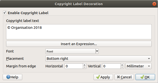
Abb. 7.8 Der Urheberrechtshinweis Dialog
Aktivieren Sie das Kontrollkästchen
Urheberrechtshinweis.Geben Sie den Copyright-Text ein, den Sie auf der Karte platzieren möchten. Über die Schaltfläche Einen Ausdruck einfügen oder bearbeiten… können Sie ihn dynamisch gestalten.
Wählen Sie die Schriftart für den Titel mit dem Schriftauswahl-Werkzeug mit allen Funktionen der QGIS Textformatierung.
Wählen Sie die Platzierung der Beschriftung in der Kartenansicht; die Optionen sind: Oben links, Oben Mitte, Oben rechts, Unten links, Unten Mitte und Unten rechts (Standard).
Optional können Sie einen horizontalen und/oder vertikalen Rand von Kante festlegen; diese Werte können in Millimetern, Pixeln oder als Prozentsatz der Breite oder Höhe der Kartenansicht angegeben werden.
Klicken Sie auf Anwenden, um zu überprüfen, ob es wie erwartet aussieht, oder auf OK, wenn Sie zufrieden sind.
7.1.6.4. Bild Dekoration
Die  Bild… Dekoration ermöglicht es Ihnen, ein Logo, eine Legende oder eine andere Abbildung auf der Kartenansicht hinzuzufügen.
Um ein Bild hinzuzufügen, gehen Sie wie folgt vor:
Wählen Sie den Menüpunkt , um den Dialog zu öffnen.
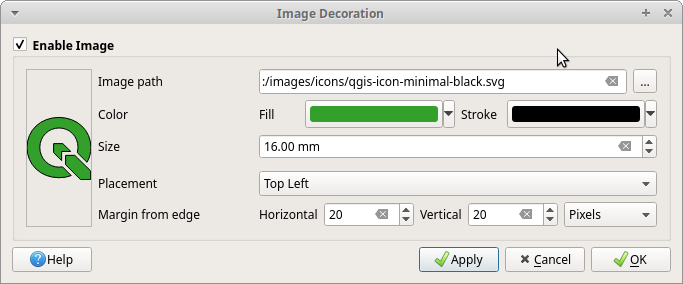
Abb. 7.9 Der Bild Dekoration Dialog
Aktivieren Sie das Kontrollkästchen
Bild aktivieren.Wählen Sie ein Bitmap- (z.B. png oder jpg) oder SVG-Bild mit der Schaltfläche … Durchsuchen aus.
Wenn Sie eine SVG-Datei gewählt haben, können Sie auch eine Farbe für die Füllung oder den Strich (Umriss) festlegen; für Bitmap-Bilder sind die Farbeinstellungen deaktiviert.
Mit der Einstellung Größe können Sie die Breite des ausgewählten Bildes in mm festlegen.
Legen Sie mit dem Auswahlmenü Platzierung fest, wo Sie das Bild auf der Kartenansicht platzieren möchten; die Standardposition ist Unten links.
Legen Sie die Werte für den Rand von der Kante fest, jeweils getrennt für Horizontal und Vertikal. Diese Werte können in Millimetern, Pixeln oder als Prozentsatz der Breite oder Höhe der Kartenansicht angegeben werden.
Klicken Sie auf Anwenden, um zu überprüfen, ob es wie erwartet aussieht und auf OK, wenn Sie zufrieden sind.
7.1.6.5. Nordpfeil
Die ![]() Nordpfeil Dekoration ermöglicht es Ihnen, einen Nordpfeil auf der Kartenansicht hinzuzufügen.
Nordpfeil Dekoration ermöglicht es Ihnen, einen Nordpfeil auf der Kartenansicht hinzuzufügen.
Um einen Nordpfeil hinzuzufügen, gehen wie folgt vor:
Wählen Sie den Menüpunkt um den Dialog zu öffnen.
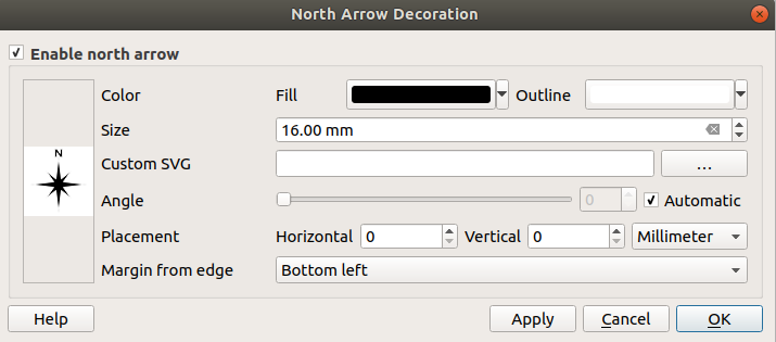
Abb. 7.10 Der Nordpfeil Dialog
Aktivieren Sie das Kontrollkästchen
Nordpfeil aktivieren.Optional können Sie die Farbe und Größe ändern oder eine benutzerdefinierte SVG für den Nordpfeil auswählen.
Optional können Sie den Winkel ändern oder Automatisch wählen, um die Richtung von QGIS steuern zu lassen.
Wählen Sie die Platzierung mit dem entsprechenden Auswahlmenü.; Standardwert ist „Unten links“.
Optional können Sie einen horizontalen und/oder vertikalen Rand von Kante festlegen; diese Werte können in Millimetern, Pixeln oder als Prozentsatz der Breite oder Höhe der Kartenansicht angegeben werden.
Klicken Sie auf Anwenden, um zu überprüfen, ob es wie erwartet aussieht und auf OK, wenn Sie zufrieden sind.
7.1.6.6. Maßstab
Mit der  Maßstab… Dekoration können Sie einen einfachen Maßstabsbalken zur Kartenansicht hinzufügen. Sie können den Stil und die Platzierung, sowie die Beschriftung des Balkens bestimmen. Der Maßstabsbalken berücksichtigt die aktive Entfernungseinheit des Projekts, wie sie in eingestellt sind.
Um einen Maßstabsbalken hinzuzufügen, gehen sie wie folgt vor:
Wählen Sie den Menüpunkt um den Dialog zu öffnen.
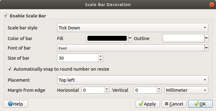
Abb. 7.11 Der Maßstab Dialog
Aktivieren Sie das Kontrollkästchen
Aktiviere Maßstab.Wählen Sie einen Stil aus dem Auswahlmenü Maßstabsstil
 .
.Wählen Sie die Balkenfarbe
 , indem Sie eine Füllfarbe (Standard: schwarz) und eine Umrissfarbe (Standard: weiß) auswählen; die Füllung und der Umriss des Maßstabsbalkens können mit dem Auswahlmenü, jeweils rechts neben der Farbeingabe, auch transparent gemacht werden.
Wählen Sie die Schriftart für den Maßstabsbalken aus dem Kombinationsfeld Balkenschriftart
aus.Stellen Sie die Größe des Maßstabs ein.
Standardmäßig ist die Option
Bei Größenänderung automatisch runde Zahlen einstellen aktiviert, um leicht lesbare Werte anzuzeigen.Legen Sie die Platzierung
mit den entsprechenden Auswahlmenü fest; Standardwert ist „Oben links“.Optional können Sie einen horizontalen und/oder vertikalen Rand von Kante festlegen; diese Werte können in Millimetern, Pixeln oder als Prozentsatz der Breite oder Höhe der Kartenansicht angegeben werden.
Klicken Sie auf Anwenden, um zu überprüfen, ob es wie erwartet aussieht, oder auf OK, wenn Sie zufrieden sind.
7.1.6.7. Layoutausdehnung
Die  Layoutausdehnung… fügt die Ausdehnungen von Kartenelement(en) aus Drucklayouts zur Kartenansicht hinzu. Wenn diese Funktion aktiviert ist, werden die Ausdehnungen aller Kartenelemente von allen Drucklayouts mit einem leicht gepunkteten Rahmen angezeigt, der mit dem Namen des Drucklayouts und des Kartenelements beschriftet ist. Sie können den Stil und die Beschriftung der angezeigten Ausdehnungen steuern. Diese Dekoration ist z. B. nützlich, wenn Sie die Positionierung von Kartenelementen wie Beschriftungen optimieren und den tatsächlich sichtbaren Bereich von Drucklayouts kennen müssen.
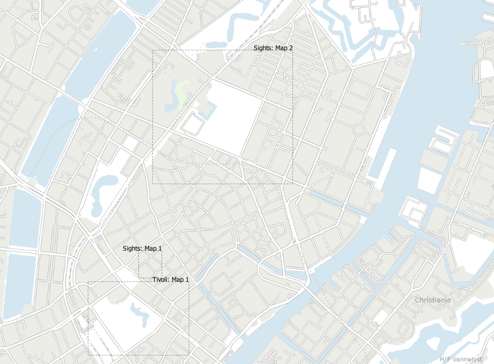
Abb. 7.12 Beispiel für die Anzeige von Layoutausdehnungen in einem QGIS-Projekt mit zwei Drucklayouts. Das Drucklayout mit dem Namen „Sights“ enthält zwei Kartenelemente, während das andere Drucklayout ein Kartenelement enthält.
Um die Layerausdehnung(en) hinzuzufügen, gehen Sie wie folgt vor:
Wählen Sie , um den Dialog zu öffnen.
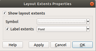
Abb. 7.13 Der Layerausdehnung Dialog
Aktivieren Sie das Kontrollkästchen
Layoutausdehnung anzeigen.Optional können Sie das Symbol und die Beschriftung der Ausdehnung ändern.
Klicken Sie auf Anwenden, um zu überprüfen, ob es wie erwartet aussieht und auf OK, wenn Sie zufrieden sind.
Tipp
Dekorationseinstellungen
Wenn Sie eine QGIS-Projektdatei speichern, werden alle Änderungen, die Sie an Gitter, Nordpfeil, Maßstabsleiste, Copyright und Layout- Ausdehnung vorgenommen haben, im Projekt gespeichert und beim nächsten Laden des Projekts wiederhergestellt.
7.1.7. Anmerkungen hinzufügen
Anmerkungen stellen eine Möglichkeit dar, in der Kartenansicht Informationen bereitzustellen, die nicht von den Layern geliefert werden können. Im Gegensatz zu den Beschriftungen, die aus Attributen des Layers erstellt werden, sind Anmerkungen unabhängige Elemente, die in der Projektdatei selbst gespeichert sind.
In QGIS gibt es zwei Kategorien von Anmerkungen:
Feature-Anmerkungen: Hierbei handelt es sich um georeferenzierte Elemente vom Typ Text, Marker, Linie oder Polygon, die in einem speziellen Layer („Beschriftungslayer“) gespeichert werden. Sie sind an eine bestimmte, geografische Position gebunden, d. h., wenn Sie Ihre Karte verschieben, den Maßstab oder die Projektion ändern, werden Ihre Anmerkungen an der Stelle bleiben, an der Sie sie gezeichnet haben.
Sprechblasen-Anmerkungen: Dies sind Anmerkungen in Form von HTML oder Formularen innerhalb einer Sprechblase. Die Sichtbarkeit dieser Anmerkungen kann mit einem Layer verknüpft werden und wird dann mit diesem sichtbar/unsichtbar gemacht. Die Größe hängt vom Maßstab der Kartenansicht ab und ihre Position kann verankert werden.
Tipp
Anmerkungen mit der Karte exportieren
Sie können die Anmerkungen zu Ihrer Karte in verschiedenen Formaten drucken/exportieren:
Werkzeuge für den Export der Kartenansichten finden Sie im Menü
Beim Drucken von Layouts müssen Sie die Option Kartenelemente zeichnen in den Elementeigenschaften des Kartenelements aktivieren sein
Die Anmerkungswerkzeugleiste bietet eine Reihe von Werkzeugen zum Erstellen und Bearbeiten von beiden Arten von Annotationen.
Werkzeug |
Funktion |
Geltungsbereich |
|---|---|---|
|
Erstellt einen neuen Layer zum Speichern von Anmerkungen |
|
Eigenschaften des Hauptbeschriftungslayers |
Einstellungen für den Hauptbeschriftungslayer |
|
|
Auswählen, Verschieben, Ändern der Größe und Ändern der Symbologieeigenschaften von Anmerkungen |
|
|
Erstellt Anmerkungen als Polygon-Feature |
|
|
Erstellt Anmerkungen als Linien-Feature |
|
|
Erstellt Anmerkungen als Punkt-Feature |
|
|
Create an annotation as a text label anchored at a point |
|
|
Erstellt Anmerkungen als geschwungenen Text entlang eines Linien-Objekts |
|
|
Create an annotation as a text label in a rectangular text box |
|
|
Create an annotation representing an |
|
|
Select and create annotation with a |
|
|
Auswählen und Erstellen von Anmerkungen, die die Attribute eines Vektor-Layers in einer benutzerdefinierten Formulardatei anzeigen |


Bemerkung
Ab QGIS 3.40 ist es nicht mehr möglich, Ballon-Anmerkungen vom Typ SVG oder Text zu erstellen. Beim Laden alter Projekte werden alle diese Anmerkungen automatisch in die neuen Elementtypen „Bild“ und „Rechteckige Textanmerkung“ konvertiert.
7.1.7.1. Feature-Anmerkungen
Feature-Anmerkungen werden in Beschriftungslayern gespeichert. Im Gegensatz zu herkömmlichen Layern ist ein Beschriftungslayer nur im aktuellen Projekt verfügbar und kann Features verschiedener Typen (Text, Marker, Linie, Polygon) enthalten. Dem Layer sind keine Attribute und keine Symbolik zugeordnet, stattdessen kann jedes einzelne Feature über das Bedienfeld Layergestaltung symbolisiert werden.
In QGIS gibt es zwei Arten von Beschriftungslayern:
Ein gewöhnlicher Beschriftungslayer: Sie können ihn mit dem Werkzeug
 Neuer Beschriftungslayer erstellen. Er wird wie jeder andere Layer im Layer Bedienfeld aufgelistet, sodass Sie z. B. die Transparenz festlegen können oder bestimmen können über und unter welchen Layern er liegt. Mit einem Doppelklick auf den Layer können Sie die Eigenschaften aufrufen.
Der Hauptbeschriftungslayer: Standardmäßig werden hier die Anmerkungen gespeichert, wenn kein anderer Beschriftungslayer im Projekt vorhanden ist oder beim Erstellen der Anmerkungen ausgewählt war. Dieser Layer wird immer ganz oben auf der Karte gezeichnet und wird nicht im Layer Bedienfeld angezeigt. Mit dem Eintrag Eigenschaften des Hauptbeschriftungslayers in der Anmerkungswerkzeugleiste können Sie den Eigenschaften-Dialog öffnen.
Beschriftungslayer-Eigenschaften
Der Eigenschaftsdialog eines Beschriftungslayers bietet die folgenden Reiter:
Information: ein schreibgeschützter Dialog, der einen nützlichen Überblick über die Informationen und Metadaten des aktuellen Layers bietet. Dazu gehören die Ausdehnung des Layers, die Anzahl der Elemente pro Beschriftungstyp, die Gesamtzahl, KBS-Details, …
Quelle: legt allgemeine Einstellungen für den Beschriftungslayer fest. Sie können hier:
Den Layernamen festlegen, der benutzt wird, um den Layer innerhalb des Projekts zu identifizieren (z. B. im Layer Bedienfeld, bei Aussrücken, …).
Zugewiesenes Koordinatenbezugssystems (KBS): Sie können das KBS des Layers ändern, indem Sie ein kürzlich verwendetes in der Dropdown-Liste auswählen oder auf die Schaltfläche
 KBS auswählen klicken (siehe Auswahl des Koordinatenbezugssystems).
Darstellung:
Mit den Einstellungen Minimum (exklusiv) und Maximum (inklusive) können Sie einen Bereich festlegen, innerhalb dem die Beschriftungen angezeigt werden, außerhalb dieses Bereichs werden sie ausgeblendet. Mit der Schaltfläche
 Auf aktuellen Kartenmaßstab setzen können Sie den aktuellen Maßstab der Kartenansicht übernehmen. Siehe Einstellen des Sichtbarkeitsmaßstabs für weitere Informationen.
Verknüpfter Layer: Ermöglicht es Ihnen, optional einen verknüpften Sichtbarkeitslayer für den Annotationslayer festzulegen. Wenn diese Option aktiviert ist, werden die Annotationen nur dann gezeichnet, wenn der verknüpfte Layer in der Karte sichtbar ist.
Deckkraft: Mit diesem Werkzeug können Sie den darunter liegenden Layer in der Kartenansicht sichtbar machen. Verwenden Sie den Schieberegler, um die Sichtbarkeit Ihres Beschriftungslayers an Ihre Bedürfnisse anzupassen. Sie können den Prozentsatz der Sichtbarkeit auch im Menü neben dem Schieberegler genau festlegen.
Mischmodus: Mit diesen Werkzeugen können Sie spezielle Rendering-Effekte erzielen: die Pixel von sich überlagernden Layern werden durch die verwendete Einstellungen gemischt.
Mit dem Zeicheneffekte Knopf können Sie Zeicheneffekte auf alle Layerobjekte anwenden.
Einige dieser Optionen sind über die Symbologie Eigenschaften der Beschriftungselemente erreichbar.
Interaktion mit Objekten
Die Feature-Anmerkungen verfügen je nach Typ über spezielle Tools zur Erstellung:
Familie / basierend auf |
Anmerkungs-Werkzeug |
Vorgehen |
|---|---|---|
Geometrie |
|
Dies entspricht der Digitalisierung eines Punkt-, Linien- oder Polygon-Vektorobjekts. Beim Erstellen von Anmerkungs-Elementen gelten alle üblichen Tastenkombinationen zum Erstellen von Objekten. Eine Linien- oder Polygon-Anmerkung wird durch Klicken mit der linken Maustaste für jeden Stützpunkt und anschließendes Klicken mit der rechten Maustaste zum Abschließen der Form gezeichnet. Während des Zeichnens kann das Einrasten aktiviert werden. Mit der Erweiterte Digitalisierung-Werkzeugleiste können Sie Stützpunkt präzise platzieren und es können auch die Geometrie-Zeichenwerkzeuge (z.B. dei „Laufende Digitalisierung“) verwendet werden. |
|
||
|
||
Text |
|
Klicken Sie mit der linken Maustaste auf die Karte. |
|
Klicken Sie mit der linken Maustaste, um der Textgrundlinie Stützpunkte hinzuzufügen, und klicken Sie mit der rechten Maustaste, um den Vorgang zu beenden. Wie oben beschrieben, stehen auch Funktionen zur Digitalisierung von Objekten zur Verfügung. |
|
|
Zeichnen Sie ein Rechteck für den Text, indem Sie zunächst mit der linken Maustaste auf die erste Ecke klicken und dann ein zweites Mal mit der linken Maustaste auf die diagonal gegenüberliegende Ecke klicken. |
|
Bild |
|
Zeichnen Sie ein Rechteckfeld für das Bild, indem Sie zunächst mit der linken Maustaste auf die erste Ecke klicken und dann ein zweites Mal mit der linken Maustaste auf die diagonal gegenüberliegende Ecke klicken. Wählen Sie dann ein Bild oder eine SVG-Datei aus dem Datei-Explorer aus. |
Im Gegensatz zu normalen Layern muss ein Beschriftungslayer nicht aktiv sein, bevor Sie ein Element auswählen können. Verwenden Sie einfach das  Beschriftung modifizieren Werkzeug, um mit den einzelnen Feature-Anmerkungen zu interagieren:
Auswahl: Klicken Sie mit der linken Maustaste auf die Beschriftung. Achtung: Standardmäßig werden Beschriftungen in der Reihenfolge angezeigt, in der sie erstellt wurden, d. h. neuere Anmerkungen werden über älteren platziert. Möglicherweise müssen Sie den Z-Index in den Symbol-Eigenschaft von Beschriftungen (über das Bedienfeld Layergestaltung) ändern, um die gewünschte Beschriftung auswählen zu können.
Verschieben: Klicken Sie mit der linken Maustaste auf ein ausgewähltes Beschriftungselement, um es zu verschieben. Ein Rechtsklick oder das Drücken der Taste Esc bricht die Verschiebung ab, während ein zweiter Linksklick die Verschiebung bestätigt. Die Verschiebung kann auch durch Drücken der Pfeiltasten gesteuert werden:
Umschalt+Pfeiltaste für große Bewegung
Alt+Pfeiltaste für eine
1 pxBewegung
Geometrie ändern: Bewegen Sie den Mauszeiger über eine Anmerkung und violette Quadrate werden an den Knotenpunkten der zugrunde liegenden Geometrie angezeigt. Klicken Sie mit der linken Maustaste auf das Quadrat, verschieben Sie es und klicken Sie erneut. Bei linearen oder polygonalen Anmerkungen wird durch Doppelklicken auf ein Segment ein neuer Stützpunkt hinzugefügt.
Löschen: Wenn Sie die Entf Taste oder die Rücktaste drücken, wenn eine Anmerkung ausgewählt ist, wird diese Anmerkung gelöscht.
Symbologie der Anmerkungen
Die Symbologie-Eigenschaften einer ausgewählten Anmerkung werden im Bedienfeld Layergestaltung angezeigt. Die folgenden Optionen stehen zur Verfügung:
Bei Polygon-, Polylinien- und Markierungs-Anmerkungen können Sie das Erscheinungsbild mithilfe aller Funktionen der Symbol-Eigenschaften ändern
Bei textbasierten Anmerkungen hilft Ihnen ein Bereich mit Textbearbeitungswerkzeugen beim Erstellen der anzuzeigenden Zeichenfolge. Diese kann mehrzeilig sein, HTML-Formatierungen enthalten und auf QGIS-Ausdrucksfunktionen zurückgreifen. Darüber hinaus können Sie das Erscheinungsbild mithilfe der vollständigen Funktionen der Textformatierungs-Eigenschaften ändern.
Je nach Art der Anmerkung stehen zusätzliche Optionen zur Verfügung:
Für Textanmerkungen an einem Punkt haben Sie die folgenden Möglichkeiten:
die Ausrichtung (links, mittig oder rechts vom Ankerpunkt) festlegen
konfigurieren, ob der Text Kartenrotation ignorieren oder Mit Karte drehen soll. In beiden Fällen kann ein benutzerdefinierter Winkel für die Ausrichtung der Elemente festgelegt werden.
Für Textanmerkungen entlang einer Linie können Sie einen Abstand von der Linie konfigurieren, wobei verschiedenen Einheiten ausgewählt werden können.
Für Textanmerkungen in einem Rechteck haben Sie folgende Möglichkeiten:
Legen Sie die Horizontale Ausrichtung (links, zentriert, rechts oder Blocksatz) und Vertikale Ausrichtung (oben, vertikal zentriert oder unten) des Textes im Rechteckfeld fest.
Konfigurieren Sie für das Rechteck den Abstand der Ränder in den Einheiten Ihrer Wahl sowie die Farben für den Rahmen und den Hintergrund.
Mit einer Bild-Anmerkung können Sie ein Rasterbild oder eine SVG-Grafik mithilfe des Werkzeugs Entfernte oder eingebettete Dateiauswahl einfügen. Die Platzierung und Größe des Bildes kann wie folgt festgelegt werden:
Maßstabsabhängige Größe: Das Bild wird mit der Karte skaliert und erscheint beim Vergrößern größer und beim Verkleinern kleiner. Die Größe wird durch eine Referenzgröße in Karteneinheiten definiert (z. B. Meter oder Grad, je nach KBS des Layers). Mit
Seitenverhältnis sperren können Sie die Größe der Anmerkung proportional zur Größe des eingebetteten Bildes beibehalten oder das Bild so strecken, dass es den Umfang der Anmerkung ausfüllt.Feste Größe: Die Bild-Anmerkung behält unabhängig vom Kartenmaßstab eine konstante Größe in Bildschirm- oder Ausgabeeinheiten (z. B. Pixel oder Millimeter) bei. Die Breite und Höhe der Anmerkung können separat eingegeben oder proportional zur Größe des eingebetteten Bildes angepasst werden.
Relativ zur Karte: Die Bild-Anmerkung wird unabhängig vom Kartenmaßstab immer an derselben Position relativ zu den Grenzen der Kartenfläche gerendert. Die Breite und Höhe der Anmerkung können separat ausgefüllt oder proportional zur Größe des eingebetteten Bildes angepasst werden.
Darüber hinaus können Sie die Anzeige von Rahmen und Hintergrund des Rechteckfeldes aktivieren und diese mithilfe der Eigenschaften von Füllungen konfigurieren.
Für Text an einem Punkt, Text innerhalb eines Rechtecks und Bild-Anmerkungen können Sie Führungslinie anzeigen verwenden, wenn der Ankerpunkt des Bildes oder Textes von seiner Standardposition versetzt ist. So erstellen Sie einen Führungslinie für eine Anmerkung:
Wählen Sie das Anmerkungsobjekt aus.
In der Mitte des Rechteckes wird der Ankerpunkt der Führungslinie als sehr kleines, grünes X sichtbar. Verschieben Sie diesen Ankerpunkt, indem Sie darauf klicken (nicht halten) und dann erneut, auf die neue Position, klicken.
Drücken Sie in den Anmerkungseigenschaften hinter dem Eintrag
Hinweislinie anzeigen die Schaltfläche …, um die Führungslinien-Eigenschaften zu konfigurieren.
Tipp
Wenn Sie eine Sprechblasenführungslinie auf eine Text- oder Bildanmerkung anwenden, erhalten Sie die alte Darstellung der Sprechblasen-Anmerkung.
Sie können einen
Referenzmaßstab konfigurieren. Damit legen Sie einen Kartenmaßstab fest, auf den sich Symbol- oder Textgrößen beziehen, die papierbasierte Einheiten (wie Millimeter oder Punkte) verwenden. Die Größen werden entsprechend skaliert, wenn die Karte in einem anderen Maßstab betrachtet wird. So wird z. B. ein Linienmerkmal mit einer Breite von 2 mm im Maßstab 1:2.000 Referenzmaßstab mit 4 mm wiedergegeben, wenn die Karte im Maßstab 1:1.000 betrachtet wird.Setzen eines Z-index: eine Beschriftung mit einem höheren Index wird über Beschriftungen mit einem niedrigeren Index gelegt. Änderungen hier sind sowohl für die Anzeige, als auch für die Auswahl von Beschriftungen hilfreich.
Änderung der Einstellungen für die Layer Darstellung.
7.1.7.2. Sprechblasen-Anmerkungen
Sie können Sprechblasen-Anmerkungen über das Menü oder über die Anmerkungswerkzeugleiste hinzufügen:
 HTML Annotation to display a HTML-formatted string
or a whole
HTML Annotation to display a HTML-formatted string
or a whole HTMLfile as an annotation. Form Annotation: useful to display attributes
of a vector layer in a customized
Form Annotation: useful to display attributes
of a vector layer in a customized .uifile. This is similar to the custom attribute forms, but displayed in an annotation item.
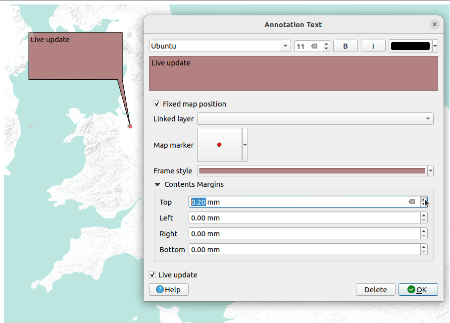
Abb. 7.14 Example of a HTML balloon annotation
Um die gewünschte Sprechblasenbeschriftung hinzuzufügen, wählen Sie das entsprechende Werkzeug aus und klicken dann auf die Kartenansicht. Eine leere Sprechblase wird hinzugefügt. Nach einem Doppelklick darauf öffnet sich ein Dialog mit verschiedenen Optionen. Dieses Dialogfeld ist für alle Beschriftungsarten nahezu identisch:
File: Fill it with the path to a
.htmlor.uifile, depending on the type of annotation, to serve as contents of the annotation.Source: Only available for HTML annotations, it allows to serve the annotation with a plain or HTML-formatted text instead of a file.
- Fixed map position: when unchecked, the balloon placement
is based on a screen position (instead of the map), meaning that it’s always shown
regardless of the map canvas extent.
Verknüpfter Layer verbindet die Beschriftung mit einem Layer aus dem Projekt, sodass die Beschriftung nur dann sichtbar ist, wenn dieser Layer sichtbar ist.
Kartenmarkierung legt das Symbol fest, das am Sprechblasen-Anker angezeigt wird (verwendet QGIS Symbologie); wird nur angezeigt, wenn Feste Kartenposition aktiviert ist.
Rahmenstil legt die Hintergrundfarbe, die Transparenz, die Strichfarbe oder die Breite der Sprechblase mit QGIS-Symbolen fest.
Inhaltsränder legt die inneren Abstände des Beschriftungsrahmens fest.
- Laufende Aktualisierung ermöglicht Ihnen eine Live-Vorschau Ihrer Änderungen.
Wenn ein Sprechblasenwerkzeug aktiv ist, können Sie auch:
Eine Anmerkung auswählen
Größe einer Anmerkung anpassen
Die Sprechblase oder den Anker auf der Kartenansicht verschieben
Eine Sprechblase löschen: markieren Sie diese und drücken Sie dann entweder die Entf Taste oder die Rücktaste, oder doppelklicken Sie darauf und drücken Sie dann Löschen im Eigenschaften-Dialog.
Mit einem Rechts-Klick das Kontextmenü öffnen; hier können Sie:
- Koordinaten kopieren: die Koordinaten des Ankers kopieren
Mit
 Bearbeiten das Eigenschaften-Fenster der Beschriftung öffnen
Die Beschriftung
 Löschen
7.1.8. Messen
7.1.8.1. Allgemeine Informationen
QGIS bietet vier Möglichkeiten, Geometrien zu messen:
Interaktives Messen-Werkzeug

Messen mit dem
 Feldrechner
Abgeleitete Messungen mit dem Objekte abfragen Werkzeug
das Vektoranalysewerkzeug:
Das Messen funktioniert in projizierten Koordinatensystemen (z.B. UTM) und unprojizierten (z.B. WGS84). Für die ersten drei Messwerkzeuge gelten die folgenden, globalen Projekteinstellungen gleichermaßen:
Im Gegensatz zu den meisten anderen GIS ist die Standard-Messung ellipsoidisch, unter Verwendung des Projekt-Ellipsoids, das in definiert ist. Dies gilt sowohl für geografische als auch für projizierte Koordinatensysteme.
Wenn Sie die projizierte/planimetrische Fläche oder Entfernung mit kartesischer Mathematik berechnen wollen, muss das Messellipsoid auf „Keine/Planimetrie“ gesetzt werden (). Wenn für die Daten und das Projekt jedoch ein geografisches (d. h. nicht projiziertes) KBS definiert ist, erfolgt die Flächen- und Entfernungsmessung ellipsoidisch.
Allerdings werden weder das Identifizierungswerkzeug noch der Feldrechner Ihre Daten vor der Messung in das Projekt KBS umwandeln. Wenn Sie dies erreichen wollen, müssen Sie das Vektoranalysewerkzeug verwenden: . Hier ist die Messung planimetrisch, es sei denn, Sie wählen die ellipsoidische Messung.
7.1.8.2. Interaktives Messen von Längen, Flächen, Kurs und Winkeln
Das Messen-Werkzeug finden Sie in der Attributwerkzeugleiste. Mit dem Auswahlmenü auf der rechten Seite des Icons können Sie zwischen Linie, Fläche, Kurs und Winkel umschalten. Die Standardeinheit, die im Dialog verwendet wird, ist die, die im Menü eingestellt ist.
Für Linie messen und Fläche messen kann ausgewählt werden, ob die Messungen  Kartesisch oder Ellipsoid vorgenommen werden sollen. Informationen dazu hält das Werkzeug bereit.
Bemerkung
Konfigurieren des Messwerkzeugs
Während der Messung von Längen oder Flächen öffnet ein Klick auf die Schaltfläche Konfiguration am unteren Rand des Messen-Fensters das Menü . Hier können Sie während der laufenden Messung Einstellungen zur Gummibandfarbe, der Genauigkeit und den Einheiten vornehmen. Sie können auch Ihre bevorzugten Maß- oder Winkeleinheiten wählen, aber bedenken Sie, dass diese Werte im aktuellen Projekt durch die Auswahl im Menü und durch die Auswahl im Messen-Fenster überschrieben werden.
Alle Messmodule verwenden die Fangeinstellungen des Digitalisierungsmodus (siehe Abschnitt Einrasttoleranz und Suchradius einstellen). Wenn Sie also genau entlang einer Linie oder um ein Polygon-Feature herum messen wollen, stellen Sie zuerst die Toleranz für das Einrasten des Layers ein. Wenn Sie nun die Messwerkzeuge verwenden, rastet jeder Mausklick (innerhalb der Toleranzeinstellung) an diesem Layer ein.
Linie messen: Mit diesem Werkzeug werden Entfernungen zwischen zwei Punkten gemessen. Jede Segmentlänge sowie die Gesamtsumme werden im Messen-Fenster angezeigt. Hier sehen Sie auch die Koordinaten aller Punkte. Die erste Zeile enthält nur Koordinaten, da sie den Ausgangspunkt darstellt. Mit der Schaltfläche Kopieren können Sie alle Linienmessungen in die Zwischenablage kopieren. Wenn Sie auf die Schaltfläche Konfiguration klicken, gelangen Sie zu Messwerkzeugkopiereinstellungen, wo Sie die Kopieroptionen festlegen können. Um die Messung zu beenden, klicken Sie mit der rechten Maustaste.
Mit der Dropdown-Liste neben der Gesamtsumme können Sie die Messeinheiten ändern, auch während einer laufenden Messung. Diese Einstellung wird dann für das Messen-Werkzeug beibehalten, bis ein neues Projekt erstellt oder ein anderes Projekt geöffnet wird.
Der Abschnitt Information im Fenster erklärt, wie die Berechnungen gemäß den verfügbaren KBS-Einstellungen durchgeführt werden.
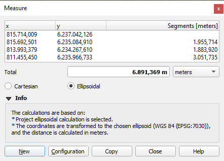
Abb. 7.15 Entfernung messen
 Fläche messen: Im Messen-Fenster wird die aufsummierte Flächengröße angezeigt. Mit einem Rechtsklick können Sie das Messen beenden. Auch hier werden Informationen zur Art der Messung zur Verfügung gestellt und es kann in laufenden Messungen die Flächeneinheit gewechselt werden.
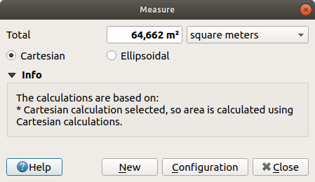
Abb. 7.16 Fläche messen
 Kurs messen: Um einen Kurs zu messen, müssen Sie zunächst mit einem Klick einen Punkt setzen. Bewegen Sie dann den Cursor, um auf den zweiten Punkt zu klicken. Das Ergebnis der Messung wird in einem Pop-up-Dialog angezeigt.
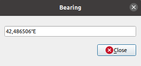
Abb. 7.17 Kurs messen
 Winkel messen: Setzten Sie zwei Punkte, um das erste Segment des Winkels zu zeichnen, den Sie messen möchten, und bewegen Sie dann den Cursor, um den gewünschten Winkel zu zeichnen. Das Ergebnis der Messung wird in einem Pop-up-Dialog angezeigt.
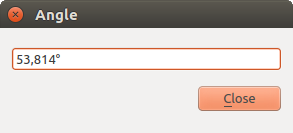
Abb. 7.18 Winkel messen
7.1.9. Weitere Kartenansichten hinzufügen
Es ist möglich, zusätzliche Kartenansichten zu öffnen, deren Darstellung von den jeweils aktuellen Einstellungen im Layer Bedienfeld abweichen kann. Um eine neue Kartenansicht hinzuzufügen, gehen Sie zu  . Ein neues Fenster öffnet sich, in dem zunächst die Darstellung der Hauptkartenansicht übernommen wird. Sie können so viele Kartenansichten hinzufügen, wie Sie benötigen. Sie können schwebend sein, nebeneinander oder als Reiter übereinander gestapelt werden.
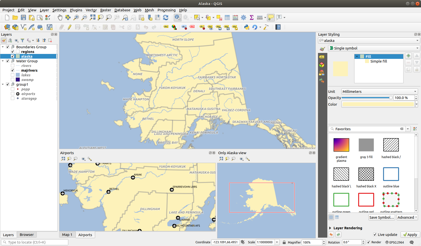
Abb. 7.19 Verschiedene Kartenansichten mit unterschiedlichen Einstellungen
Am oberen Rand jeder Kartenansicht befindet sich eine Werkzeugleiste mit den folgenden Möglichkeiten:
 Volle Ausdehnung,
  Zu ausgewählten Objekten zoomen und
  Auf Layer zoomen um in der Ansicht zu navigieren
 Kartenthema der Ansicht setzen: hiermit können Sie das Kartenthema zur Anzeige in dieser Kartenansicht auszuwählen. Wenn es auf
 (keine)eingestellt ist, folgt die Darstellung den Änderungen im Layer Bedienfeld. Ansichtseinstellungen: hier können Sie die Kartenansicht wie folgt konfigurieren:
- Ansichtszentrum mit Hauptkarte synchronisieren: synchronisiert die Mitte der Kartenansichten, ohne den Maßstab zu ändern; so können Sie eine Übersichtskarte oder eine vergrößerte Karte erstellen, die der Mitte der Kartenansicht folgt.
 Ansicht mit Auswahl synchronisieren: das gleiche wie Zu ausgewählten Objekten zoomen
Maßstab
Drehung
Vergrößerung
- Maßstäbe synchronisieren: der Maßstab wird mit dem der Hauptkarte synchron gehalten. Ein Maßstabsfaktor kann dann angegeben werden, so dass Sie eine Ansicht erhalten, die immer z.B. den zweifachen Maßstab der Hauptkarte hat.
- Anmerkungen anzeigen
- Cursor-Position anzeigen
- Hauptkartenausdehnung anzeigen
- Beschriftungen anzeigen: erlaubt es die Beschriftungen auszublenden, auch wenn sie in den Einstellungen des Layers aktiviert sind
Karten-KBS ändern…
Ansicht umbenennen…
7.1.10. Exportieren der Kartenansicht
Die von Ihnen erstellten QGIS-Projekte können als komplexe Layouts oder Berichte in verschiedene Formate exportiert werden. Es ist aber auch möglich, die aktuelle Darstellung in der Kartenansicht direkt zu exportieren, ohne ein zusätzliches Layout zu erstellen. Dieser schnelle „Screenshot“ der Kartenansicht hat einige praktische Funktionen.
Um die aktuelle Darstellung im Kartenfenster zu exportieren, gehen Sie wie folgt vor:
Wählen Sie aus der Menüleiste
abhängig davon, was Sie exportieren möchten, wählen Sie eine der folgenden Optionen:
 Karte als Bild speichern …
 Karte als PDF exportieren…
Die beiden Export-Dialoge bieten Ihnen verschiedene Einstellungsmöglichkeiten:
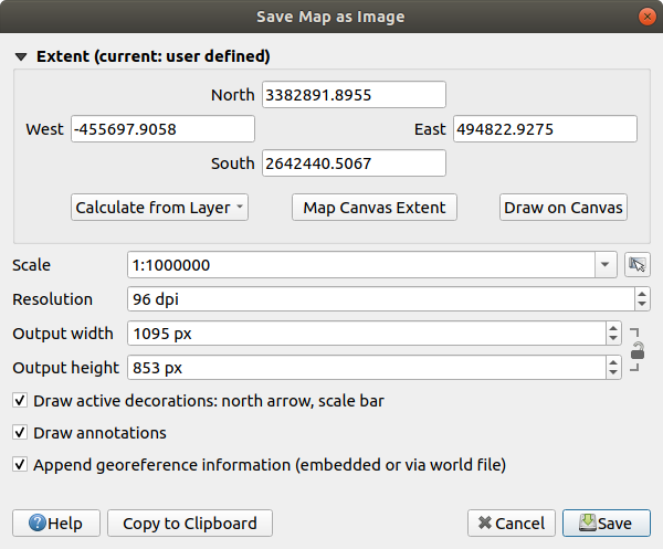
Abb. 7.20 Der Dialog zum Speichern der Kartenansicht als Bild-Datei
Wählen Sie die zu exportierende Ausdehnung: Optionen sind die aktuellen Kartengrenzen (Standard), die Ausdehnung eines Layers oder eine benutzerdefinierte Ausdehnung, die über der Kartenansicht aufgezogen wird. Die Koordinaten des ausgewählten Bereichs werden angezeigt und können manuell bearbeitet werden.
Sie können auch einen Maßstab eingeben oder ihn aus der Liste der Vordefinierten Maßstäbe auswählen. Wenn Sie den Maßstab ändern, wird die Ausdehnung für den Export vom Zentrum aus angepasst.
Geben Sie eine Auflösung für die Ausgabe an
Kontrollieren Sie die Ausgabebreite und Ausgabehöhe des Bildes in Pixeln. Sie basieren standardmäßig auf der aktuellen Auflösung und Ausdehnung, können aber angepasst werden und verändern den Ausschnitt der Kartenansicht (vom Zentrum aus). Das Größenverhältnis kann fixiert werden, was besonders praktisch ist, wenn die Ausdehnung auf der Kartenansicht gezeichnet wird.
- Aktive Dekorationen anzeigen: Wenn Sie Dekorationen (Maßstabsleiste, Titel, Gitter, Nordpfeil…) für die Kartenansicht aktiviert haben, werden diese mit exportiert
- Bemerkungen zeichnen: Alle Beschriftungen der Kartenansicht werden mit exportiert
- Geofererenzierungsinformationen anhängen (eingebettet oder als World-Datei): Je nach Ausgabeformat wird eine gleichnamige World-Datei (mit der Erweiterung
PNGWfürPNG-Bilder,JPGWfürJPG, …) im gleichen Ordner wie Ihr Bild gespeichert. DasPDF-Format bettet die Informationen in die PDF-Datei ein. Beim PDF-Export stehen im Dialog Karte als PDF speichern… noch weitere Optionen zur Verfügung:
Abb. 7.21 Der Dialog zum Speichern der Kartenansicht als PDF-Datei
- RDF-Metadaten exportieren wie z. B. Titel, Autor, Datum, werden mit exportiert
- Geospatial-PDF erzeugen: Erzeugt eine georeferenzierte PDF-Datei. Sie haben folgende Optionen:
Wählen Sie das Geodaten-PDF Format
- Vektorlayerinformationen einschließen: wenn diese Option aktiviert ist, werden alle Geometrie- und Attributinformationen von Objekten, die auf der Karte sichtbar sind, in die ausgegebene Geodaten-PDF-Datei einbezogen. ACHTUNG!!! Es werden tatsächlich ALLE Attribute aus den Tabellen ALLER Layer eingeschlossen. Vorsicht also bei sensiblen Daten! Durch die Entfernung des entsprechenden Häckchens unter Attribute einschließen kann dieses Verhalten angepasst werden.
Bemerkung
Eine Geospatial-PDF-Datei kann ebenfalls als Datenquelle in QGIS verwendet werden. Weitere Informationen zur Unterstützung von Geospatial-PDF-Dateien in QGIS finden Sie unter https://north-road.com/2019/09/03/qgis-3-10-loves-geospatialpdf/.
Karte rastern
- Geometrien für kleinere Dateigrößen vereinfachen: Geometrien werden während des Exports der Karte vereinfacht, indem Knotenpunkte entfernt werden, die sich bei der Exportauflösung nicht deutlich unterscheiden (z.B. wenn die Exportauflösung
300 dpibeträgt, werden Eckpunkte, die weniger als1/600 Zollauseinander liegen, entfernt). Dies kann die Größe und Komplexität der Exportdatei reduzieren (sehr große Dateien können u. U. in anderen Anwendungen nicht geladen werden). Stellen Sie mit der Option Textexport ein, ob Textbeschriftungen immer oder vorzugsweise als Text oder Pfade exportiert werden sollen.
Klicken Sie Speichern, um einen Namen und einen Pfand festzulegen
Beim Exportieren als Bild ist es auch möglich, das erwartete Ergebnis der obigen Einstellungen in die Zwischenablage zu kopieren und die Karte in einer anderen Anwendung einzufügen.