Fontos
A fordítás közösségi munka, amihez itt tud csatlakozni. Ennek az oldalnak eddig 44.75%-a van lefordítva.
12.3. Szerkesztés
QGIS has various capabilities for editing OGR, SpatiaLite, PostgreSQL, MS SQL Server and Oracle Spatial vector layers and tables. They can be of 2D or 3D geometry type.
Megjegyzés
GRASS rétegek szerkesztési eljárása eltérő – lásd a Digitizing and editing a GRASS vector layer fejezetet a részletekért.
Figyelem
Párhuzamos szerkesztés
A QGIS nem követi, hogy valaki más önnel egy időben ugyanazt az elemet szerkeszti. A szerkesztéseit utolsóként elmentő személy győz.
Javaslat
Szerkesztések ellenőrzése
A folyamatos ellenőrzés bekapcsolható rétegenként a fülön. Továbbiak a Digitizing Properties fejezetben.
12.3.1. Illesztési tolerancia és keresési sugár beállítása
A menü több paramétert biztosít a szerkesztőeszközök viselkedésének konfigurálásához. További információk a Digitalizálási beállítások fejezetben.
A vektorrétegek optimális és pontos szerkesztéséhez be kell állítani az elemek töréspontjainak megfelelő illesztési tolerancia és a keresési sugár értékét. Az Illesztés csoport biztosítja a kapcsolódó beállításokat, nevezetesen az illesztési toleranciát és a keresési sugarat.
Illesztési tolerancia: Amikor egy új töréspontot ad meg vagy egy létezőt mozgat, az illesztési tolerancia az a távolság, amit a QGIS a legközelebbi olyan töréspont vagy szakasz kereséséhez használ, amihez csatlakozni lehet. Ha nincs ilyen az illesztési tolerancián belül, akkor a QGIS az egérgomb felengedési helyén hagyja a töréspontot, ahelyett hogy illesztené azt egy meglévő törésponthoz vagy szakaszhoz.
The tolerance setting affects all tools that work with snapping and applies by default to new layers and projects. It can however be overridden at layer level (see Illesztési és digitalizálási beállítások).
Keresési sugár: Keresési sugár a töréspontok szerkesztéséhez az a távolság amit a QGIS a töréspontok kiválasztásához használ, amikor a térképre kattint. Ha ez nem keresési sugáron belül történik, a QGIS egy töréspontot sem talál, és egyiket sem választja ki szerkesztésre.
Az illesztési tolerancia és a keresési sugár térképi egységben vagy pixelben állítható be. Lehet, hogy kísérleteznie kell a megfelelő érték megtalálásához. Ha túl nagy toleranciát ad meg, előfordulhat, hogy a QGIS rossz törésponthoz illeszt, különösen akkor, ha nagy számú egymáshoz közeli töréspont található ott. Minél kisebb a keresési sugár, annál nehezebb lesz eltalálni a mozgatandó töréspontot.
12.3.2. Illesztési és digitalizálási beállítások
A globális illesztési és digitalizálási beállítások (illesztési mód, tolerancia, mértékegységek, stb.) a projekten belül felülbírálhatóak a menüben. Az Illesztési és digitalizálási beállításokban más tulajdonságokat is beállíthat (illesztett rétegek, méretarány korlátozása, topológia, stb.). Az Illesztési eszköztár ezek közül a legtöbbhez hozzáférést biztosít.
Alapértelmezés szerint az illesztés ki van kapcsolva a projektben ameddig megnyomja az  Illesztés engedélyezése gombot vagy megnyomja az kbd:S billentyűt. Az illesztési mód, tolerancia és mértékegységek is beállíthatók ezen az eszköztáron.
12.3.2.1. Illesztési tulajdonságok
Három lehetőség van annak a réteg(ek)nek a kiválasztására, amihez illeszteni kell:
Minden réteg: gyors beállítás az összes látható rétegre a projektben, így az egérmutatót az összes törésponthoz és szakaszhoz illeszti. A legtöbb esetben ennek az illesztési módnak a használata megfelelő, de vigyázzon, ha sok vektorréteget tartalmazó projekttel használja, mivel ez hatással lehet a teljesítményre.
Aktuális réteg: csak az aktív réteget használja, kényelmes módja a szerkesztett rétegen belül a topológiai konzisztencia biztosításának.
Bővített beállítások: rétegenként lehetővé teszi az illesztés bekapcsolását és a mód, tolerancia és mértékegység, átfedés és méretarány beállítását (lásd 12.82. ábra). Ha az egyik réteget szerkeszti, és egy másik töréspontjaihoz szeretne illeszteni, győződjön meg róla, hogy a a cél réteget kijelölte, és növelje meg az illesztési toleranciát egy nagyobb értékre. Az illesztés nem történik meg azokra a rétegekre, melyeket nem jelölt ki az illesztési beállítások párbeszédablakban.
When moving or creating vertex, you can opt for the following snapping modes:
 Vertex
 Segment: snaps along a line or a polygon perimeter.
If topological editing is enabled, then a new vertex is added at the snapping location.
Segment: snaps along a line or a polygon perimeter.
If topological editing is enabled, then a new vertex is added at the snapping location. Area: guarantees that the snap point lies anywhere on a polygon’s area,
not necessarily on its boundary
Area: guarantees that the snap point lies anywhere on a polygon’s area,
not necessarily on its boundary Centroid: snaps to the centroid of the geometry of a feature.
In case of a multipart geometry, the target point may be distinct from the existing parts.
Centroid: snaps to the centroid of the geometry of a feature.
In case of a multipart geometry, the target point may be distinct from the existing parts. Middle of Segments on line or polygon feature
 Line Endpoints: snaps to the first or last vertex of every part
of a line or polygon feature.
Line Endpoints: snaps to the first or last vertex of every part
of a line or polygon feature.
A QGIS különböző illesztés ikont jelenít meg az illesztés típusának függvényében:
Törésponthoz illesztés: négyzet ikon |
Szakaszhoz illesztés: homokóra ikon |
Metszéshez illesztés: kereszt ikon |
Megjegyezzük, hogy ezeknek az ikonoknak a színét meg lehet változtatni a globális beállítások Digitalizálás lapján.
A tolerancia érték vagy a projekt térképi egységében vagy pixelben állítható be. A pixel választásának előnye, hogy az illesztést a méretaránytól függetlenül állandó értéken tartja. 10-12 pixel általában jó érték, de függ a képernyő DPI értékétől. A térképi egység használata lehetővé teszi, hogy a toleranciát valós terepi méretekhez kösse. Például, ha van az elemek között egy minimális távolság, ez a beállítás biztosíthatja, hogy ne adjon meg egymáshoz túl közeli töréspontokat.
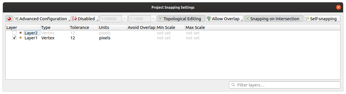
12.82. ábra Illesztési beállítások (Bővített beállítások mód)
Megjegyzés
Alapértelmezés szerint csak a látható elemekhez illeszthetünk (azok az elemek, melyek stílusa megjelenik, kivéve azokat a rétegeket, ahol a jelrendszer „Nincsenek szimbólumok”). Engedélyezheti az illesztést nem látható elemekhez is az  Illesztés engedélyezése a láthatatlan elemekhez bekapcsolásával a fülön.
Javaslat
Illesztés engedélyezése alapértelmezetten
Az illesztést alapértelmezetten engedélyezheti az összes új projekthez a fülön. Az alapértelmezett illesztési módot, a tolerancia értéket és a mértékegységeket is beállíthatja, ezek jelennek meg majd a Illesztési beállítások párbeszédablakban.
12.3.2.2. Illesztés engedélyezése a metszéseknél
Egy másik lehetséges beállítás az  Illesztés a metszéseknél használata, mely lehetővé teszi az metszéspontra illesztést az illesztésre engedélyezett rétegeken, még akkor is, ha nincs töréspont a metszésnél.
12.3.2.3. Illesztés korlátozása egy méretarány-tartományra
Néhány esetben az illesztés nagyon lassúvá válhat. Ezt gyakran az elemek mennyisége okozza néhány rétegen, melyek összetett indexelést és karbantartást igényelnek. Pár paraméterrel az illesztést lehet csak akkor engedélyezni, ha a térképnézet megfelelő méretarány-tartományba esik. Ez lehetővé teszi, hogy csak olyan méretarányban történjen meg az illesztéssel járó költséges indexszámítást, ahol a rajzolás releváns lehet.
Az illesztés méretarányának korlátozása a alatt konfigurálható. A méretarányra korlátozás csak Bővített beállítások módban érhető el.
Három mód áll rendelkezésre az illesztés méretarány-tartományra korlátozásához:
Letiltva: Az illesztés engedélyezett az aktuális térkép méretaránytól függetlenül. Ez az alapértelmezett mód.
Globális: Az illesztést korlátozza és csak akkor engedélyezi, ha a térkép aktuális méretaránya a globális minimum és maximum közé esik. Amikor ezt a módot választja, két beviteli mező válik aktívvá annak a méretarány-tartománynak a beállításához, melyben az illesztés engedélyezett.
Rétegenként: Az illesztési méretarány-tartományt rétegenként külön lehet megadni. Amikor ezt a módot választja két oszlop jelenik meg a minimum és maximum méretarány beállításához minden rétegnél.
Vegye figyelembe, hogy a minimum és maximum méretarány követi a QGIS konvencióit: a minimum méretarány a legjobban lekicsinyített méretarány, míg a maximum a leginkább felnagyított. A „0” vagy „nincs beállítva” értékre állított minimum vagy maximum méretarány a korlátozás kikapcsolását jelenti.
12.3.2.4. Önmagához illesztés
Az  Önmagához illesztés beállítás lehetővé teszi, hogy az éppen szerkesztett geometriához illesszen. A Bővitett digitalizálás panellel kombinálva praktikus módot biztosít az új élek digitalizálására relatívan az előző élekhez vagy töréspontokhoz képest. Az önmagához illesztés érvénytelen geometriákat okozhat, óvatosan használja.

12.83. ábra Elemek rajzolása önmagához illesztéssel
12.3.2.5. Illesztés egyéni rácsra
Az illesztési távolság is beállítható rétegenként a Digitalizálás fülön a rétegtulajdonságok párbeszédablakban. A Geometria pontossága távolságának beállítása engedélyez egy pontokkal jelölt rácsot, amely akkor látható, ha a térképvászon a megjelenítéshez megfelelő méretarányban van. Ilyenkor a rács pontjaira illesztés fog történni: egy új vagy módosított geometria összes pontját automatikusan a legközelebbi rácspontra illeszti. További információk a Digitizing Properties fejezetben.
12.3.3. Topologikus szerkesztés
Ezeken az illesztési beállítások kívül az Illesztési beállítások… párbeszédablakban ( eszköztárban engedélyezhet vagy tilthat további topológiai funkcionalitást.
12.3.3.1. Topologikus szerkesztés engedélyezése
A  Topologikus szerkesztés gomb segít, ha közös határvonalú elemeket kezel. Ennek a opciónak a bekapcsolásával a QGIS «detektálja» a közös határokat. Amikor közös töréspontokat vagy szakaszokat mozgat, a QGIS a szomszéd elem geometriáját is elmozgatja.
A topologikus szerkesztés különböző rétegek elemeivel is működik, amennyiben a rétegek láthatóak és szerkesztési módban vannak.
A Z vagy M értékekkel rendelkező rétegeken a topologikus szerkesztés interpolálja a töréspontok Z vagy M értékeit az összekapcsolt él értéke alapján.
12.3.3.2. Átfedés szabályozása
Az átfedés szabályozása megakadályozza, hogy a korábbiakat átfedő újabb elemet rajzoljon a kiválasztott rétegen, ezzel felgyorsítva a szomszédos poligonok digitalizálását. Az átfedés eszközzel szabályozhatja. Három mód lehetséges:
 Átfedés engedélyezése (alapértelmezett)
 Átfedés elkerülése az aktív rétegen: megakadályozza az átfedést a többi elemmel az éppen szerkesztett rétegen. Ha úgy digitalizálja az újabb geometriát, hogy az átfedi a meglévő szomszédokat, a QGIS levágja az átfedő részeket, és az új geometriát a már meglévő elemek határához illeszti. Ennek előnye, hogy nem kell digitalizálnia a közös töréspontokat a határon.
 Bővített beállítások követése: lehetővé teszi a rétegenkénti átfedési beállításokat Bővített beállítások módban.
Megjegyzés
Ha egy új geometriát teljesen átfednek a már meglévő, akkor a QGIS törli azt és megjelenít egy hibaüzenetet.
Figyelem
Óvatosan használja az Átfedések elkerülése beállítást
Mivel ez a beállítás bármelyik poligonréteggel átfedő új geometriát le fogja vágni, nem várt eredményt kaphat, ha elfelejti kikapcsolni, amikor már nincs rá szüksége.
12.3.3.3. Automatikus követés
Általában a térképszerkesztési eszközök használatakor (elem hozzáadása, rész hozzáadása, gyűrű hozzáadása, átformálás és felosztás) rá kell kattintani az elem minden egyes töréspontjára. Az automatikus nyomkövetési móddal felgyorsíthatja a digitalizálási folyamatot, mivel nem kell többé manuálisan elhelyeznie az összes töréspontot a bevitel során:
A
 Követés eszközt bekapcsolhatja az ikon megnyomásával az Illesztés eszköztáron vagy a T billentyű megnyomásával.
Illesszen egy törésponthoz vagy szakaszhoz a követni kívánt elemen.
Mozgassa az egeret egy másik töréspont vagy szakasz fölé, melyhez illeszteni akar, a szokásos egyenes vonal helyett a digitalizálási gumiszalag az utolsó illesztett ponttól az aktuális pozícióig tartó útvonalat ábrázolja. Az eszköz görbéket tartalmazó geometriák esetén is működik.
A QGIS az alapul szolgáló elemek topológiáját használja a két pont közötti legrövidebb útvonal megtalálásához. A nyomkövetéshez az illesztést be kell kapcsolni a nyomkövetésre használt rétegeken. Digitalizáláskor egy meglévő töréspontra vagy szakaszra kell illesztenie, és biztosítani kell a topológiai összeköttetést meglévő elemek szakaszaival, különben a QGIS nem képes összekötni őket, és egy egyenes szakaszt fog követni.
Kattintson, és a QGIS elhelyezi a közbenső töréspontokat a megjelenített útvonalat követve.
Ha vonalkövetés helyett az elemekkel párhuzamos útvonalat szeretne digitalizálni, nyissa le a Követés engedélyezése ikont, és állítsa be az Eltolás értéket. Pozitív érték a követés irányához képest balra tolja el az új vonalat, a negatív az ellenkező oldalra.
Megjegyzés
Állítsa be a térkép méretarányát és az illesztési paramétereket az optimális követéshez
Ha túl sok elem van a térképi megjelenítésben, a követés le lesz tiltva, elkerülve a sokáig tartó nyomkövetési adatstruktúra előkészítését és a nagy memória igényt. Nagyítás vagy pár réteg kikapcsolása után a nyomkövetés újra engedélyezve lesz.
Megjegyzés
Nem ad hozzá topológiai pontokat
Ez az eszköz nem ad pontokat a már meglévő geometriához, akkor sem. ha a Topologikus szerkesztés engedélyezett. Ha a szerkesztett rétegen a geometriai élesség be van kapcsolva, akkor az eredményül kapott geometria elképzelhető, hogy nem követi pontosan a meglévő geometriát.
Javaslat
Gyorsan be- és kikapcsolhatja az automatikus követést a T billentyűvel
A T gomb megnyomásával a nyomkövetés bármikor be- és kikapcsolható (akár egy elem digitalizálása közben is), így lehetőség van az elem egyes részeinek digitalizálására bekapcsolt nyomkövetéssel, más részeit pedig kikapcsolt nyomkövetéssel. Az eszközök a szokásos módon működnek, ha a nyomkövetés ki van kapcsolva.
Javaslat
Követés átalakítása görbévé
A segítségével görbéket is létrehozhat a digitalizálás során. Lásd a digitalizálási beállítások fejezetet.
12.3.4. Egy meglévő réteg digitalizálása
Alapértelmezés szerint a QGIS-be betöltött rétegek csak olvashatók, amivel elkerülhető a réteg módosítása egy véletlen egérmozdulattal. Azonban bármelyik réteget szerkesztheti, amennyiben az adatszolgáltató támogatja azt (lásd: Exploring Data Formats and Fields), és az alapul szolgáló adatforrás írható (azaz a fájlok nem csak olvashatók).
Javaslat
Rétegszerkesztési jogosultság korlátozása a projekten belül
A táblázatból kiválaszthatja, hogy valamelyik réteg csak olvasható legyen, függetlenül a szolgáltató jogosultságaitól. Ez egy praktikus módja lehet többfelhasználós környezetben, hogy jogosulatlan felhasználók tévedésből ne módosítsák a rétegeket (pl. Shapefile), és ezáltal megsérüljenek az adatok. Vegye figyelembe, hogy ez a beállítás csak az aktuális projekten belül érvényes.
Általánosságban elmondható, hogy a vektorrétegek szerkesztésére szolgáló eszközök egy digitalizálási és egy bővített digitalizálási eszköztárra oszthatók, amely leírása a Advanced digitizing fejezetben olvasható. Mindkettőt bekapcsolhatja és kikapcsolhatja a alatt.
Az alap digitalizálási eszközökkel a következőket hajthatja végre:
Eszköz |
Cél |
Eszköz |
Cél |
|---|---|---|---|
|
Az összes vagy a kiválasztott rétegek módosításainak egyidejű mentése, visszaállítása vagy visszavonása |
|
A kiválasztott réteg(ek) szerkesztési állapotának be- és kikapcsolása az aktív réteg állapota alapján |
|
Szerkesztések mentése az aktív rétegbe |
||
|
Digitalizálás egyenes szakaszokkal |
|
Digitalizálás ívekkel |
|
Szabadkézi digitalizálás engedélyezése |
|
Poligon vagy szabályos alakzat digitalizálása |
|
Új rekord hozzáadása |
|
Elem hozzáadása: Pont digitalizálása |
|
Elem hozzáadása: Vonal digitalizálása |
|
Elem hozzáadása: Poligon digitalizálása |
|
Töréspont eszköz (minden réteg) |
|
Töréspont eszköz (aktuális réteg) |
|
Beállítja, hogy a töréspontszerkesztő panel automatikusan megnyíljon-e |
|
Kiválasztott elemek attribútumainak módosítása egyszerre |
|
Kiválasztott elemek törlése az aktuális rétegről |
|
Elemek kivágása az aktív rétegről |
|
Kiválasztott elemek másolása az aktív rétegről |
|
Elemek beillesztése az aktív rétegre |
|
Módosítások visszavonása az aktív rétegen |
|
Visszavont változások újbóli végrehajtása az aktív rétegen |


Megjegyezzük, hogy miközben egy digitalizáló eszközt használ, a nagyítás és eltolás elvégezhető a térképvásznon anélkül, hogy a fókuszt elvesztené az eszköz.
Minden szerkesztési munkamenet a  Szerkesztés be-/kikapcsolása kiválasztásával kezdődik. Az opció az adott réteg helyi menüjéből, az attribútumtábla párbeszédablakában, a digitalizálási eszköztáron vagy a menüből érhető el.
Ha a réteg szerkesztési módban van, további gombok válnak aktívvá a szerkesztés eszköztáron, valamint jelölők jelennek meg az összes elem töréspontjain, kivéve, ha a Jelölők megjelenítése csak a kiválasztott elemekhez opció a fülön be van kapcsolva.
Javaslat
Mentsen rendszeresen
Végezze el rendszeresen a  Réteg szerkesztéseinek mentését. Ezzel azt is ellenőrizheti, hogy az adatforrás képes-e elfogadni az összes módosítást.
12.3.4.1. Geometriaszerkesztési technikák
Ha egy vonal- vagy poligonrétegen egy geometriarajzoló eszköz (első sorban azok, amelyek elemeket adnak hozzá, osztanak fel, alakítanak át) engedélyezve van, akkor kiválaszthatja az új töréspontok hozzáadásának módját:
 Digitalizálás szakaszokkal: egyenes szakaszokat rajzol, amelynek kezdő- és végpontjai bal kattintással határozhatóak meg.
 Digitalizálás görbékkel: íves vonalat rajzol három egymást követő csomópont alapján, amelyeket bal kattintással határozhat meg (kezdet, ív mentén lévő pont, vég). Ha a geometria típusa nem támogatja a görbéket, akkor a görbület közelítésére egymást követő rövid szakaszkákat használ.
 Folyamatos digitalizálás: vonalakat rajzol szabadkézi módban, azaz a csomópontok a kurzor mozgását követve lesznek hozzáadva a térképvászonhoz, figyelembe véve az Illesztési toleranciát. Az illesztési tolerancia meghatározza az egymást követő töréspontok közötti távolságot. Jelenleg az egyetlen támogatott egység a pixel (
px). Ebben az üzemmódban csak a kezdő bal kattintásra és a befejező jobb kattintásra van szükség. Alakzat digitalizálása: elindítja az Alakzat digitalizálási eszköztár eszközeit szabályos alakú sokszög rajzolásához.
A digitalizáló eszközök közötti váltáskor a kiválasztott módszer nem változik. Ugyanazon geometria rajzolása közben az első három módszert bárhogy kombinálhatja.
12.3.4.2. Elemek hozzáadása
A réteg típusától függően használhatja az eszköztár  Rekord hozzáadása,
  Pontelem hozzáadása,
  Vonalelem hozzáadása vagy
  Poligonelem hozzáadása ikonját, hogy új elemet adjon hozzá az aktuális réteghez.
Geometria nélküli elem hozzáadásához kattintson a Rekord hozzáadása gombra és a megnyíló eleműrlapon megadhatja az attribútumokat.
Ha a térbeli eszközökkel hoz létre elemeket, először digitalizálja a geometriát, majd adja meg az attribútumait. A geometria digitalizálásához:
(Opcionális, mivel ez az alapértelmezett) Válassza ki a
Digitalizálás szakasszal geometriarajzolási módszertKattintson a bal gombbal a térképterületre az új elem első pontjának létrehozásához. Pontelemek esetében ez elegendő, és szükség esetén megnyitja az eleműrlapot az attribútumok kitöltéséhez.
Vonal- vagy poligongeometria esetén folytassa a további pontok rögzítését bal egérgombbal kattintva. Az egyes töréspontok pontos pozicionálásához támaszkodhat az elemekhez illesztés opcióira, a rácshoz illesztésre, illetve a speciális digitalizálás panelre.
A töréspontok közötti szakaszok egyenkénti megrajzolása mellett a vonalakat és poligonokat lehet:
rajzolni automatikus követéssel, meggyorsítva vele a digitalizálást. Ez az elhelyezett töréspontok között, a meglévő elemeket követve, egymás utáni vonalszakaszokat hoz létre.
szabad kézzel digitalizálni megnyomva az R billentyűt vagy aktiválva a
Folyamatos digitalizálást.görbeként megrajzolni a Ctrl+Shift+G billentyűkombinációval, vagy aktiválva a
Digitalizálás görbével eszközt.
Megjegyzés
Vonal- vagy poligongeometriák digitalizálása közben oda-vissza válthat a geometriarajzolási módszerek között, lehetővé téve elemek hozzáadását egyenes szakaszok, szabad kézzel rajzoltak és íves részek tetszőleges vegyítésével.
Az utolsó, tévesen felvett pont törléséhez nyomja meg a Delete vagy Backspace billentyűt.
Ha elkészült a pontok hozzáadásával, kattintson bárhova a térképen jobb gombbal, véglegesítve ezzel az elem geometriájának rajzolását.
Javaslat
Digitalizálási gumiszalag testreszabása
Poligon digitalizálásakor az alapértelmezett piros gumiszalag kitakarhatja az alatta lévő elemeket vagy azokat a helyeket, ahova pontot szeretne helyezni. Ezen segíthet, ha alacsonyabb átlátszatlanságot (vagy alfa csatornát) állít be a gumiszalag Kitöltőszínénél a menüben. A gumiszalagot le is tilthatja a Töréspont szerkesztése közben ne frissítse a gumiszalagot bejelölésével.
Vonalelemeknél a Shift + jobb-kattintás automatikusan bezárja a vonalat.
Megjelenik az attribútumablak, amelyben megadhatja az új elem adatait. A 12.84. ábra egy fiktív új folyó attribútumainak beállítását mutatja. Ennek kapcsán a menü Digitalizálás lapján beállíthatja:
 Ne ugorjon fel az attribútuműrlap az elemek létrehozása után, hogy ne nyíljon meg az űrlap;
- A legutóbb megadott attribútumértékek újbóli felhasználása, hogy a mezők automatikusan kitöltődjenek az űrlap megnyitásakor, és csak a módosult értékeket kelljen beírni.
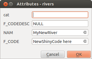
12.84. ábra Attribútumértékek megadása új vektorelem digitalizálása után
12.3.4.3. Töréspont eszköz
A QGIS két eszközt biztosít a vektoros elemek töréspontjaival való munkához:
 Töréspont eszköz (jelenlegi réteg): csak az aktív réteg (a Rétegek panelen) elemeit kezeli
 Töréspont eszköz (összes réteg): az összes szerkeszthető réteg minden elemét kezeli. Ez lehetővé teszi az elemek szerkesztését az aktív réteg váltása nélkül, vagy egyszerre több réteg szerkesztését (pl. országok és régióik határai).
Bármely szerkeszthető vektoros réteg esetében a töréspont eszköz a CAD programokhoz hasonló módon biztosítja az elemek töréspontjainak kezelését. Lehetőség van egyszerre több töréspont kijelölésére, és ezek egyszerre történő mozgatására, hozzáadására vagy törlésére. A töréspont eszközök támogatják a topológiai szerkesztési módot is. A kijelölés tartós, így amikor valamelyik művelet befejeződik, a kijelölés aktív marad az adott elem és eszköz esetében.
Javaslat
Drawing a series of new vertices
The vertex tool does not support automatic tracing and is optimized for
editing individual vertices and moving or deleting an arbitrary selection
of multiple vertices. Try using the  Reshape Features
tool when you need to replace or insert a series of new vertices,
especially if you want to trace other features.
Reshape Features
tool when you need to replace or insert a series of new vertices,
especially if you want to trace other features.
Fontos, hogy a  Keresési sugár:
  tulajdonságot nullánál nagyobb számra állítsa. Ellenkező esetben a QGIS nem fogja tudni megállapítani, hogy melyik csúcsot kell szerkeszteni, és figyelmeztetést fog megjeleníteni.
Javaslat
Töréspont jelölők
A QGIS különböző kinézetű töréspontjelölőket támogat: „Félig átlátszó kör”, „Kereszt” és „Nincs”. A jelölő stílusának megváltoztatásához válassza a menüpontot a , kattintson a Digitalizálás lapra, és válassza ki a megfelelő bejegyzést.
Alapműveletek
Adott egy szerkesztési módban lévő réteg. Aktiválja a töréspont szerkesztőt. A töréspontok fölé víve az egeret piros karikák jelennek meg.
Töréspontok kiválasztása:
Kattintson rájuk egyesével lenyomva tartott Shift billentyűvel
Kattintson és húzzon egy téglalapot a kiszemelt töréspontok köré
Húzzon sokszöget a kiszemelt töréspontok köré: nyomva tartott Alt billentyűvel kattintson a töréspont eszközzel, és rajzoljon egy sokszöget. Az egyes kattintások új töréspontot adnak hozzá a sokszög gumiszalagjához. A Backspace vagy Delete törli a gumiszalag utoljára hozzáadott töréspontját. Az Esc kilép a sokszöges kijelölési módból, és ezzel együtt törli a gumiszalag töréspontjait. Jobb kattintás véglegesíti a sokszöget, és kijelöli a sokszögön belüli töréspontokat.
Amikor egy töréspont ki van választva, a színe kékre változik. A kijelöléshez további töréspontokat úgy lehet hozzáadni, hogy Shift billentyűt nyomva tartva megismételjük az előbbieket. Töréspontokat a kijelölésből eltávolítani nyomva tartott Ctrl billentyűvel lehet.
Javaslat
Elem kiválasztásához kötött töréspont eszköz
Vertices can be selected across different features (or layers). If you are looking for vertices of a specific feature in a crowded place, first select that feature. Then draw the rectangle or polygon selector with the vertex tool around the vertices: only the selected feature’s vertices are selected.
Ez akkor is így működik, ha az elemet a töréspontszerkesztő panelen jeleníti meg.
Csoportos töréspont-kiválasztási mód: A csoportos kiválasztási mód a Shift+R billentyűkombináció megnyomásával aktiválható. Válassza ki az első töréspontot egyetlen kattintással, majd vigye az egeret kattintás nélkül egy másik töréspontra. Ez dinamikusan kiválasztja az összes köztes töréspontot a legrövidebb útvonal irányában (poligonok esetén).
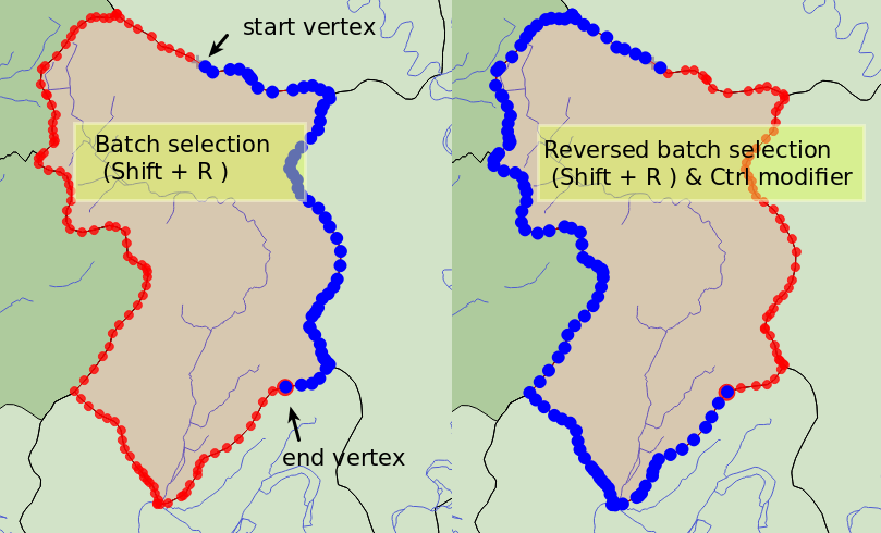
12.85. ábra Töréspontok csoportos kijelölése Shift+R billentyűkombinációval
A Ctrl megnyomásával a kijelölés megfordul, és a leghosszabb útvonalat választja ki az elem határvonala mentén. Fejezze be a töréspontok kiválasztását egy második kattintással, vagy az Esc megnyomásával lépjen ki a csoportos módból.
Töréspontok hozzáadása: Pontot hozzáadni egy vonal vagy poligon geometriájához a Shift billentyűt nyomva tartva és a szakaszon a kívánt helyre duplán kattintva lehet.
Az egeret egy szakasz fölé víve annak középpontjánál egy virtuális csomópont jelenik meg. Kattintson rá, húzza az egeret a megfelelő helyre, majd kattintson újból az új töréspont hozzáadásához. Vonalgeometria esetén a virtuális csomópont annak két végén is megjelenik: könnyedén meghosszabbíthatja a meglévő vonalat erre a pontra kattintva, majd további kattintásokkal és végül jobb kattintással befejezve a rajzolást.
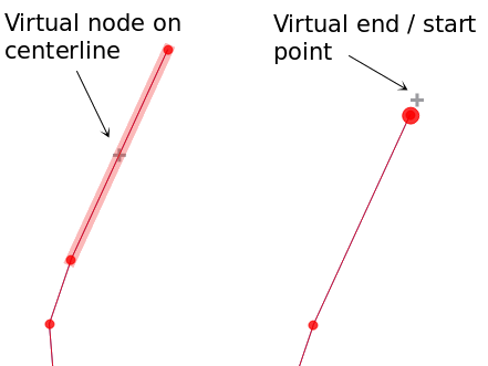
12.86. ábra Töréspontok hozzáadása virtuális csomópontokkal
Töréspontok törlése: Válassza ki a töréspontokat, majd nyomja meg a Delete billentyűt. Egy elem összes töréspontjának törlése geometria nélküli elemet eredményez – amennyiben az adatforrás ezt támogatja. Ez nem törli magát az elemet, csak a geometriáját. A teljes elem törléséhez használja a
 Kiválasztottak törlése eszközt.
Töréspontok mozgatása: Válassza ki az összes mozgatandó töréspontot, kattintson egy kiválasztott töréspontra vagy élre, majd kattintson a kívánt új helyre. A második kattintás előtt használhatja az illesztési beállításokat és a Bővített digitalizálás panel távolságra, szögre, pontos x és y koordinátákra vonatkozó korlátozásait. Az összes kiválasztott töréspont el lesz tolva.
Ha azonban a rácshoz illesztés engedélyezve van, a kiválasztott töréspontok a legközelebbi megfelelő rácsponthoz lesznek eltolva. A ki nem választott töréspontok is átkerülnek a legközelebbi rácspontba. Nem egyszerű eltolás történik.
12.87. ábra A felső töréspont eltolásakor az összes töréspont a rácshoz lesz illesztve
Converting adjacent segments to/from curve: Select the center vertex of the segment you want to convert, hit the O letter key. If the vertex was in a curve, the curve is converted into straight lines. If the vertex was between two straight lines, they are converted into a curve. A first or a last vertex of a line can’t be converted to a center vertex curve. The layer must be compatible with curve geometry type.
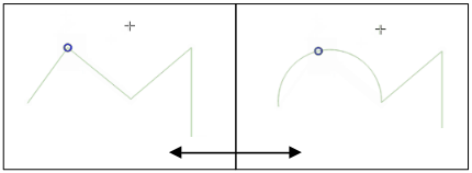
12.88. ábra Switch from curve to straight lines with O letter
A töréspont eszközzel végzett minden módosítás külön bejegyzést hoz létre a Visszavonás panelen. Ne feledje, hogy minden művelet támogatja a topológiai szerkesztést, ha ez be van kapcsolva. A menet közbeni vetítés is támogatott.
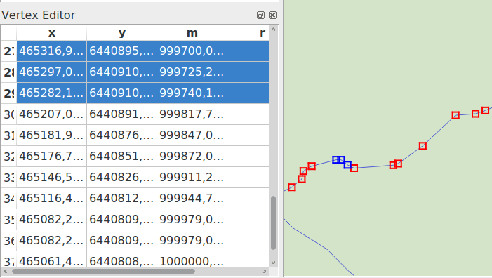
A töréspontszerkesztő panel
Egy töréspont eszközt engedélyezve megnyithatja a Töréspontszerkesztő panelt. Jobb gombbal kattintva egy elemre betölti a panelre az elem töréspontjainak x, y (és z, m ha van) koordinátáit és az r értékét (sugár, íves geometria esetén). Az elem szerkesztése kizárólagossá válik, ami azt jelenti, hogy a többi elem szerkesztése ilyenkor le van tiltva:
A táblázatban egy sor kijelölése kiválasztja a megfelelő töréspontot a térképvásznon, és fordítva.
A térképvásznon való kattintás vagy húzás csak az adott elem töréspontjait és szakaszait fogja kiválasztani vagy mozgatni
Ha megváltoztat egy koordinátát a táblázatban, a töréspont pozíciója frissül. Ez egy kényelmes módja a töréspont Z koordinátája vagy M értéke szerkesztésének.
Több sort is kijelölhet és törölheti őket egyszerre.
Új töréspontokat csak a táblázathoz kötött elemhez lehet hozzáadni
Ha nem szeretné, hogy a Töréspontszerkesztő panel azonnal megjelenjen minden alkalommal, amikor a töréspont eszközökkel műveletet végez (és ezzel esetleg elrejtse a többi panelt, vagy megzavarja a panelek elhelyezését), vegye ki a pipát a Táblázat automatikus megnyitása elől a panel tetején található  Beállítások menüben. Ezután be is zárhatja a panelt. A panel újbóli megnyitásához jobb egérgombbal kell kattintania egy panel vagy eszköztár fölött, és ki kell választania a listából, vagy be kell jelölnie a Töréspontszerkesztő megjelenítése bejegyzést a Digitalizálás eszköztáron.
12.89. ábra A töréspontszerkesztő panelen láthatóak a kiválasztott pontok
12.3.4.4. Z koordináta és M érték hozzárendelésének szabályai
A 3D vektoros elemek vagy M értékkel rendelkező elemek digitalizálása nem sokban különbözik az (X,Y) 2D rétegektől. Az ebben a fejezetben ismertetett eszközök és lehetőségek továbbra is rendelkezésre állnak, és segítenek a töréspont vagy pont elhelyezésében a síkban. Ezután szükség lehet a Z koordináta (vagy M érték) hozzárendelésének kezelésére:
Alapértelmezés szerint a QGIS az új töréspontokhoz a lapon beállított Alapértelmezett Z értéket (illetve Alapértelmezett M értéket) rendeli hozzá. Ha a Bővített digitalizálási panel használatban van, akkor az értéket annak z (illetve m) mezőjéből veszi.
Törésponthoz illesztésnél az új vagy mozgatott töréspont az illesztett töréspont Z vagy M értékét kapja meg.
Szakaszhoz illesztésnél, bekapcsolt topológiai szerkesztés mellett, az új töréspont Z vagy M értéke a szakasz mentén lesz interpolálva.
Ha a Bővített digitalizálási panel z (illetve m) mezője
 zárolva van, akkor annak az értékét kapja meg a töréspont, nem pedig az illesztett töréspont vagy szakasz Z vagy M értékét.
To edit Z or M values of an existing feature, you can use the Vertex editor panel. To create features with custom Z or M values you may want to rely on the Advanced Digitizing Panel.
12.3.4.5. Elemek kivágása, másolása és beillesztése
Selected features can be cut, copied and pasted between layers in the same
QGIS project, as long as destination layers are set to
Toggle editing beforehand.
Javaslat
Poligon átalakítása törtvonallá és fordítva, másolás, beillesztés használatával
Copy a line feature and paste it in a polygon layer: QGIS pastes in the target layer a polygon whose boundary corresponds to the closed geometry of the line feature. This is a quick way to generate different geometries of the same data.
Features can also be pasted to external applications as text. That is, the features are represented in CSV format, with the geometry data appearing in the OGC Well-Known Text (WKT) format. WKT and GeoJSON features from outside QGIS can also be pasted to a layer within QGIS.
When would the copy and paste function come in handy? Well, it turns
out that you can edit more than one layer at a time
and copy/paste features between layers. Why would we want to do this?
Say we need to do some work on a new layer but only need one or two
lakes, not the 5,000 on our big_lakes layer.
We can create a new layer and use copy/paste to plop the needed lakes
into it.
Példaként tavakat fogunk átmásolni egy új rétegre:
Töltse be a réteget, amelyről másolni akar (forrás réteg)
Töltse be vagy hozza létre a réteget, amelyre másolni akar (cél réteg)
Indítsa el a szerkesztést a cél rétegen
Make the source layer active by clicking on it in the legend
Use the
 Select Features by area or single click
tool to select the feature(s) on the source layer
Select Features by area or single click
tool to select the feature(s) on the source layerClick on the
 Copy Features tool
Make the destination layer active by clicking on it in the legend
Click on the
 Paste Features tool
Stop editing and save the changes
What happens if the source and target layers have different schemas (field names and types are not the same)? QGIS populates what matches and ignores the rest. If you don’t care about the attributes being copied to the target layer, it doesn’t matter how you design the fields and data types. If you want to make sure everything - the feature and its attributes - gets copied, make sure the schemas match.
When you paste features into another layer,
QGIS checks the attribute values against the constraints defined
in the destination layer (for example, NOT NULL, Unique, or expression constraints).
If one or more pasted features contain invalid attribute values that
do not meet these constraints, a dialog will
appear, listing all affected features and fields.
When pasting a single feature, you can decide whether to:
Edit the invalid values directly in the dialog. The corrected values will be used when pasting.
Paste Anyway: the feature is pasted as-is, even with invalid values.

12.90. ábra Dialog for handling invalid attribute values when pasting a single feature
When pasting multiple features, the dialog lists all invalid fields across all features, allowing bulk review and correction. You can decide per field or per feature whether to:
Edit the invalid values directly in the dialog. The corrected values will be used when pasting.
Discard All: no features pasted.
Discard All Invalid: pasted only features with valid attribute values.
Paste All (Including Invalid): all features are pasted as-is, even with invalid values.
Skip: skip the specific feature, allowing proceeding with the rest.

12.91. ábra Dialog for handling invalid attribute values when pasting multiple features
Megjegyzés
Congruency of Pasted Features
If your source and destination layers use the same projection, then the pasted features will have geometry identical to the source layer. However, if the destination layer is a different projection, then QGIS cannot guarantee the geometry is identical. This is simply because there are small rounding-off errors involved when converting between projections.
Javaslat
Copy string attribute into another
If you have created a new column in your attribute table with type «string» and want to paste values from another attribute column that has a greater length the length of the column size will be extended to the same amount. This is because the GDAL Shapefile driver knows to auto-extend string and integer fields to dynamically accommodate for the length of the data to be inserted.
12.3.4.6. Deleting Selected Features
If we want to delete an entire feature (attribute and geometry), we can do that
by first selecting the geometry using the regular Select
Features by area or single click tool. Selection can also be done from the attribute
table. Once you have the selection set, press Delete or Backspace
key or use the Delete Selected tool to delete
the features. Multiple selected features can be deleted at once.
The  Cut Features tool on the digitizing toolbar can
also be used to delete features. This effectively deletes the feature but
also places it on a „spatial clipboard”. So, we cut the feature to delete.
We could then use the Paste Features tool to put it back,
giving us a one-level undo capability. Cut, copy, and paste work on the
currently selected features, meaning we can operate on more than one at a time.
Cut Features tool on the digitizing toolbar can
also be used to delete features. This effectively deletes the feature but
also places it on a „spatial clipboard”. So, we cut the feature to delete.
We could then use the Paste Features tool to put it back,
giving us a one-level undo capability. Cut, copy, and paste work on the
currently selected features, meaning we can operate on more than one at a time.
12.3.4.7. Undo and Redo
The  Undo and
  Redo tools allows you to undo or redo
vector editing operations. There is also a dockable widget, which shows all
operations in the undo/redo history (see 12.92. ábra). This widget is not
displayed by default; it can be displayed by right-clicking on the toolbar and
activating the Undo/Redo Panel checkbox. The Undo/Redo capability
is however active, even if the widget is not displayed.
Redo tools allows you to undo or redo
vector editing operations. There is also a dockable widget, which shows all
operations in the undo/redo history (see 12.92. ábra). This widget is not
displayed by default; it can be displayed by right-clicking on the toolbar and
activating the Undo/Redo Panel checkbox. The Undo/Redo capability
is however active, even if the widget is not displayed.
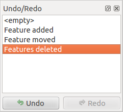
12.92. ábra Redo and Undo digitizing steps
When Undo is hit or Ctrl+Z (or Cmd+Z) pressed, the state of all features and attributes are reverted to the state before the reverted operation happened. Changes other than normal vector editing operations (for example, changes done by a plugin) may or may not be reverted, depending on how the changes were performed.
To use the undo/redo history widget, simply click to select an operation in the history list. All features will be reverted to the state they were in after the selected operation.
12.3.4.8. Szerkesztett rétegek mentése
When a layer is in editing mode, any changes remain in the memory of QGIS.
Therefore, they are not committed/saved immediately to the data source or disk.
If you want to save edits to the current layer but want to continue editing
without leaving the editing mode, you can click the
Save Layer Edits button. When you turn editing mode off with
Toggle editing (or quit QGIS for that matter),
you are also asked if you want to save your changes or discard them.
If the changes cannot be saved (e.g., disk full, or the attributes have values that are out of range), the QGIS in-memory state is preserved. This allows you to adjust your edits and try again.
Javaslat
Adatintegritás
It is always a good idea to back up your data source before you start editing. While the authors of QGIS have made every effort to preserve the integrity of your data, we offer no warranty in this regard.
Saving multiple layers at once
This feature allows the digitization of multiple layers. Choose
 Save for Selected Layers to save all changes you
made in multiple layers. You also have the opportunity to
Save for Selected Layers to save all changes you
made in multiple layers. You also have the opportunity to
 Rollback for Selected Layers, so that the
digitization may be withdrawn for all selected layers.
If you want to stop editing the selected layers,
Rollback for Selected Layers, so that the
digitization may be withdrawn for all selected layers.
If you want to stop editing the selected layers,  Cancel
for Selected Layer(s) is an easy way.
Cancel
for Selected Layer(s) is an easy way.
The same functions are available for editing all layers of the project.
Javaslat
Use transaction group to edit, save or rollback multiple layers changes at once
When working with layers from the same PostGreSQL database, activate the Automatically create transaction groups where possible option in to sync their behavior (enter or exit the edit mode, save or rollback changes at the same time).
12.3.5. Advanced digitizing
Ikon |
Cél |
Ikon |
Cél |
|---|---|---|---|
|
Enable Advanced Digitizing Tools |
||
|
Move Feature(s) |
|
Copy and Move Feature(s) |
|
Rotate Feature(s) |
|
Simplify Feature |
|
Scale Feature |
||
|
Add Ring |
|
Add Part |
|
Fill Ring |
|
Swap direction |
|
Delete Ring |
|
Delete Part |
|
Offset Curve |
|
Reshape Features |
|
Split Parts |
|
Split Features |
|
Merge Attributes of Selected Features |
|
Merge Selected Features |
|
Rotate Point Symbols |
|
Offset Point Symbols |
|
Trim or Extend Feature |


12.3.5.1. Move Feature(s)
The  Move Feature(s) tool allows you to move existing features:
Select the feature(s) to move.
Click on the map canvas to indicate the origin point of the displacement; you can rely on snapping capabilities to select an accurate point.
You can also take advantages of the advanced digitizing constraints to accurately set the origin point coordinates. In that case:
First click on the
 button to enable the panel.
Type
xand enter the corresponding value for the origin point you’d like to use. Then press the button next to the option to lock the value.Do the same for the
ycoordinate.Click on the map canvas and your origin point is placed at the indicated coordinates.
Move over the map canvas to indicate the destination point of the displacement, still using snapping mode or, as above, use the advanced digitizing panel which would provide complementary
distanceandangleplacement constraints to place the end point of the translation.Click on the map canvas: the whole features are moved to new location.
Likewise, you can create a translated copy of the feature(s) using the
 Copy and Move Feature(s) tool.
Megjegyzés
If no feature is selected when you first click on the map canvas with any of the Move Feature(s) or Copy and Move Feature(s) tools, then only the feature under the mouse is affected by the action. So, if you want to move several features, they should be selected first.
12.3.5.2. Rotate Feature(s)
Use the  Rotate Feature(s) tool to rotate one or multiple
features in the map canvas:
Rotate Feature(s) tool to rotate one or multiple
features in the map canvas:
Press the
Rotate Feature(s) iconThen click on the feature to rotate. The feature’s centroid is referenced as rotation center, a preview of the rotated feature is displayed and a widget opens showing the current Rotation angle.
Click on the map canvas when you are satisfied with the new placement or manually enter the rotation angle in the text box. You can also use the Snap to ° box to constrain the rotation values.
If you want to rotate several features at once, they shall be selected first, and the rotation is by default around the centroid of their combined geometries.
You can also use an anchor point different from the default feature centroid: press the Ctrl button, click on the map canvas and that point will be used as the new rotation center.
If you hold Shift before clicking on the map, the rotation will be done in 45 degree steps, which can be modified afterwards in the user input widget.
To abort feature rotation, press the ESC button or click on the
Rotate Feature(s) icon.
12.3.5.3. Scale Feature
The  Scale Feature tool is similar to the Rotate feature. Though instead of performing
a rotation of selected features, it rescales their geometry. The change is
performed in relation to the anchor point and the scale ratio can be manually specified
in the widget that appears in the upper corner of the canvas.
Scale Feature tool is similar to the Rotate feature. Though instead of performing
a rotation of selected features, it rescales their geometry. The change is
performed in relation to the anchor point and the scale ratio can be manually specified
in the widget that appears in the upper corner of the canvas.
12.3.5.4. Simplify Feature
The  Simplify Feature tool allows you to interactively
reshape a line or polygon geometry by reducing or densifying the number of
vertices, as long as the geometry remains valid:
Simplify Feature tool allows you to interactively
reshape a line or polygon geometry by reducing or densifying the number of
vertices, as long as the geometry remains valid:
Select the
Simplify Feature tool.Click on the feature or drag a rectangle over the features.
A dialog pops up allowing you to define the Method to apply, ie whether you would like to:
simplify the geometry, meaning less vertices than the original. Available methods are
Simplify by distance,Simplify by snapping to gridorsimplify by area (Visvalingam). You’d then need to indicate the value of Tolerance inLayer units,Pixelsormap unitsto use for simplification. The higher the tolerance is the more vertices can be deleted.or densify the geometries with new vertices thanks to the
Smoothoption: for each existing vertex, two vertices are placed on each of the segments originated from it, at an Offset distance representing the percentage of the segment length. You can also set the number of Iterations the placement would be processed: the more iterations, the more vertices and smoother is the feature.
Settings that you used will be saved when leaving a project or an edit session. So you can go back to the same parameters the next time you simplify a feature.
A summary of the modifications that would apply is shown at the bottom of the dialog, listing number of features and number of vertices (before and after the operation and the ratio the change represents). Also, in the map canvas, the expected geometry is displayed over the existing one, using the rubberband color.
When the expected geometry fits your needs, click OK to apply the modification. Otherwise, to abort the operation, you can either press Cancel or right-click in the map canvas.
Megjegyzés
Unlike the feature simplification option in menu which simplifies the geometry just for rendering,
the Simplify Feature tool permanently modifies
feature’s geometry in data source.
12.3.5.5. Add Part
You can  Add Part to a selected feature generating a
multipoint, multiline or multipolygon feature. The new part must be digitized
outside the existing one which should be selected beforehand.
Add Part to a selected feature generating a
multipoint, multiline or multipolygon feature. The new part must be digitized
outside the existing one which should be selected beforehand.
The Add Part can also be used to add a geometry to a geometryless
feature. First, select the feature in the attribute table and digitize the new
geometry with the Add Part tool.
Megjegyzés
Order of vertices in polygon parts
Unlike the OGC standards, QGIS doesn’t constrain vertices of the exterior boundary of a polygon feature to be ordered counterclockwise. Thus, you can find both directions in a layer. However, every parts of the same multipolygon feature will have their outer vertices ordered following the same direction.
You can however use the Force right-hand-rule algorithm to constrain features of a layer to have vertices of their outer boundaries ordered in the clockwise direction.
12.3.5.6. Delete Part
The  Delete Part tool allows you to delete parts from
multifeatures (e.g., to delete polygons from a multi-polygon feature). This
tool works with all multi-part geometries: point, line and polygon. Furthermore,
it can be used to totally remove the geometric component of a feature.
To delete a part, simply click within the target part.
Delete Part tool allows you to delete parts from
multifeatures (e.g., to delete polygons from a multi-polygon feature). This
tool works with all multi-part geometries: point, line and polygon. Furthermore,
it can be used to totally remove the geometric component of a feature.
To delete a part, simply click within the target part.
12.3.5.7. Add Ring
You can create ring polygons using the  Add Ring icon in the toolbar.
This means that inside an existing area, it is possible to digitize further polygons
that will occur as a «hole», so only the area between the boundaries
of the outer and inner polygons remains as a ring polygon.
Add Ring icon in the toolbar.
This means that inside an existing area, it is possible to digitize further polygons
that will occur as a «hole», so only the area between the boundaries
of the outer and inner polygons remains as a ring polygon.
To add a ring:
Select the feature(s) to modify
Activate the
Add Ring toolDraw a polygon within the selected geometries, using the aforementioned techniques. A hole appears in the selected geometries.
If no geometry is selected when the ring is drawn, then a hole is added to each of the polygons the ring is drawn over.
Megjegyzés
Order of vertices in polygon rings
Unlike the OGC standards, QGIS doesn’t constrain vertices of the exterior boundary of a polygon feature to be ordered counterclockwise. Thus, you can find both directions in a layer. However, every rings of the same (multi)polygon feature will have their vertices ordered in the opposite direction to the outer boundary’s.
You can however use the Force right-hand-rule algorithm to constrain features of a layer to have vertices of their outer boundaries ordered in the clockwise direction, and vertices of their interior rings ordered in the counter-clockwise direction.
12.3.5.8. Fill Ring
The  Fill Ring tool helps you create polygon feature that
totally falls within another one without any overlapping area; that is the new
feature covers a hole within the existing one. To create such a feature:
Fill Ring tool helps you create polygon feature that
totally falls within another one without any overlapping area; that is the new
feature covers a hole within the existing one. To create such a feature:
Select the
Fill Ring tool.Draw a new polygon over the existing feature: QGIS adds a ring to its geometry (like if you used the
Add Ring tool) and creates a new
feature whose geometry matches the ring (like if you traced
over the interior boundaries with the Add polygon
feature tool).Or alternatively, if the ring already exists on the feature, place the mouse over the ring and left-click while pressing Shift: a new feature filling the hole is drawn at that place.
The Feature Attributes form of the new feature opens, pre-filled with values of the „parent” feature and/or fields constraints.
12.3.5.9. Delete Ring
The  Delete Ring tool allows you to delete rings within
an existing polygon, by clicking inside the hole. This tool only works with
polygon and multi-polygon features. It doesn’t
change anything when it is used on the outer ring of the polygon.
Delete Ring tool allows you to delete rings within
an existing polygon, by clicking inside the hole. This tool only works with
polygon and multi-polygon features. It doesn’t
change anything when it is used on the outer ring of the polygon.
12.3.5.10. Reshape Features
You can reshape line and polygon features using the
Reshape Features tool on the toolbar. For lines, it replaces the line
part from the first to the last intersection with the original line.
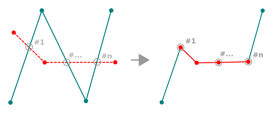
12.93. ábra Reshape line
Javaslat
Extend linestring geometries with reshape tool
Use the Reshape Features tool to extend existing linestring
geometries: snap to the first or last vertex of the line and draw a new one.
Validate and the feature’s geometry becomes the combination of the two lines.
For polygons, it will reshape the polygon’s boundary. For it to work, the reshape tool’s line must cross the polygon’s boundary at least twice. To draw the line, click on the map canvas to add vertices. To finish it, just right-click. Like with the lines, only the segment between the first and the last intersections is considered. The reshape line’s segments that are inside the polygon will result in cropping it, where the ones outside the polygon will extend it.
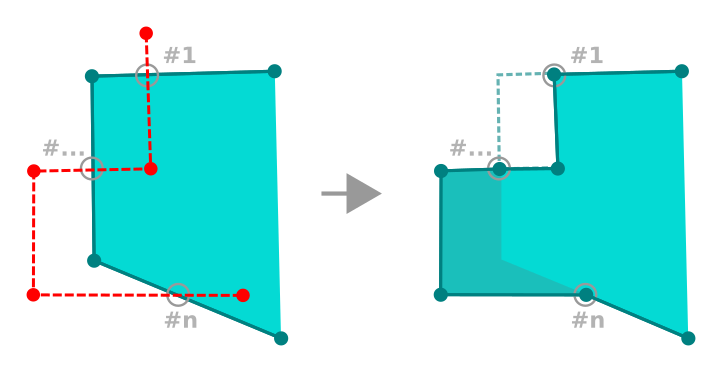
12.94. ábra Reshape polygon
With polygons, reshaping can sometimes lead to unintended results. It is mainly useful to replace smaller parts of a polygon, not for major overhauls, and the reshape line is not allowed to cross several polygon rings, as this would generate an invalid polygon.
Megjegyzés
The reshape tool may alter the starting position of a polygon ring or a closed line. So, the point that is represented «twice» will not be the same any more. This may not be a problem for most applications, but it is something to consider.
12.3.5.11. Offset Curves
The  Offset Curve tool creates parallel shifts of
line layers.
The tool can be applied to the edited layer (the geometries are modified)
or also to background layers (in which case it creates copies of the lines /
rings and adds them to the edited layer).
It is thus ideally suited for the creation of distance line layers.
The User Input dialog pops-up, showing the displacement distance
and other settings.
Offset Curve tool creates parallel shifts of
line layers.
The tool can be applied to the edited layer (the geometries are modified)
or also to background layers (in which case it creates copies of the lines /
rings and adds them to the edited layer).
It is thus ideally suited for the creation of distance line layers.
The User Input dialog pops-up, showing the displacement distance
and other settings.
To create a shift of a line or polygon layer, you must first go into editing mode
and activate the Offset Curve tool.
Then click on a feature to shift it.
Move the mouse and click where wanted or enter the desired distance in
the user input widget. Holding Ctrl during the 2nd click will make an offset copy.
Your changes may then be saved with the
Save Layer Edits tool.
For geometries on background layers make sure that snapping is on and hold Ctrl to select the geometry from the background. Also hold Ctrl when doing the second click. Geometries will be converted to the target layer geometry type.
QGIS options dialog (Digitizing tab then Curve offset tools section) or
the  icon in the User Input dialog allows
you to configure some parameters like Join style,
Quadrant segments, Miter limit and End cap style.
icon in the User Input dialog allows
you to configure some parameters like Join style,
Quadrant segments, Miter limit and End cap style.
12.3.5.12. Reverse Line
Changing the direction of a line geometry can be useful for cartographical purposes (e.g., for orienting symbols or labels that follow the line direction) or when preparing for network analysis where the direction of flow or travel matters.
This tool works only on line layers. For multipart lines, you can reverse individual parts without affecting the other parts of the feature.
To change a line direction:
Select a line layer in the Layers panel and make it editable.
Activate the reverse line tool by clicking
 Reverse line in the Advanced Digitizing toolbar.
Move the pointer over a line feature. The part under the cursor is highlighted.
Click on the line: the direction of the line (or part) is reversed.
You can reverse other lines by clicking on them.
Javaslat
For bulk line direction changes, use the Reverse line direction processing algorithm which can reverse all lines in a layer or a selection at once.
12.3.5.13. Split Features
Use the  Split Features tool to split a feature into two
or more new and independent features, ie. each geometry corresponding to a new
row in the attribute table.
Split Features tool to split a feature into two
or more new and independent features, ie. each geometry corresponding to a new
row in the attribute table.
To split line or polygon features:
Select the
Split Features tool.Draw a line across the feature(s) you want to split. If a selection is active, only selected features are split. The original feature is then assigned the biggest geometry resulting from the splitting, and new features are created for the remaining parts. Fields of the features are filled/updated according to the datasource provider rules or their splitting policy.
You can then as usual modify any of the attributes of any resulting feature.
Javaslat
Split a polyline into new features in one-click
Using the Split Features tool, snap and click on an
existing vertex of a polyline feature to split that feature into two new features.
12.3.5.14. Split parts
In QGIS it is possible to split the parts of a multi part feature so that the
number of parts is increased. Just draw a line across the part you want to split using
the  Split Parts icon.
Javaslat
Split a polyline into new parts in one-click
Using the Split Parts tool, snap and click on an
existing vertex of a polyline feature to split the feature into two new
polylines belonging to the same feature.
12.3.5.15. Merge selected features
The  Merge Selected Features tool allows you to create
a new feature by merging existing ones: their geometries are merged to generate
a new one. If features don’t have common boundaries,
a multipolygon/multipolyline/multipoint feature is created.
Merge Selected Features tool allows you to create
a new feature by merging existing ones: their geometries are merged to generate
a new one. If features don’t have common boundaries,
a multipolygon/multipolyline/multipoint feature is created.
First, select the features you’d like to combine.
Then press the
Merge Selected Features button.In the new dialog, the Merge line at the bottom of the table shows the attributes of the resulting feature. If any Merge policy have been defined, they are automatically applied to populate this row. However, you can override these values manually. Modify the values in the following ways:
manually replacing the value in the corresponding cell;
selecting a row in the table and pressing Take attributes from selected feature to use the values of this initial feature;
pressing the Take attributes from the largest geometry to use the attributes from the longest line feature, the largest polygon, or the multipoints with the most parts;
pressing Skip all fields to use empty attributes;
expanding the drop down menu at the top of the table, select any of the above options to apply to the corresponding field only. There, you can also choose to aggregate the initial features attributes (Minimum, Maximum, Median, Sum, Count, Concatenation… depending on the type of the field. see Statisztikai összegzés panel for the full list of functions).
Megjegyzés
If the layer has default values or clauses present on fields, these are used as the initial value for the merged feature.
Press OK to apply the modifications. A single (multi)feature is created in the layer, replacing the previously selected ones.
12.3.5.16. Kiválasztott elemek attribútumainak összevonása
The  Merge Attributes of Selected Features tool
allows you to apply same attributes to features without merging their boundaries.
The dialog is the same as the
Merge Attributes of Selected Features tool
allows you to apply same attributes to features without merging their boundaries.
The dialog is the same as the Merge Selected Features tool’s except that
unlike that tool, selected objects are kept with their geometry while some of their
attributes are made identical.
12.3.5.17. Rotate Point Symbols
The  Rotate Point Symbols allows you to individually
change the rotation of point symbols in the map canvas.
Rotate Point Symbols allows you to individually
change the rotation of point symbols in the map canvas.
First, you need to indicate the field to store the rotation value in. This is made by assigning a field to the symbol data-defined rotation property:
In the dialog, browse to the symbol editor dialog.
Click the
 Data-defined override widget near the
Rotation option of the top Marker level (preferably)
of the symbol layers.
Data-defined override widget near the
Rotation option of the top Marker level (preferably)
of the symbol layers.Choose a field in the Field Type combobox. Values of this field are hence used to rotate each feature’s symbol accordingly.
You can also check the Store data in project entry to generate an auxiliary data storage field to control the rotation value.
Megjegyzés
Make sure that the same field is assigned to all the symbol layers
Setting the data-defined rotation field at the topmost level of the symbol tree automatically propagates it to all the symbol layers, a prerequisite to perform graphical symbol rotation with the Rotate Point Symbols tool. Indeed, if a symbol layer does not have the same field attached to its rotation property, the tool will not work.
12.95. ábra Pontszimbólum forgatása
Then click on a point symbol in the map canvas with the
Rotate Point Symbols toolMove the mouse around. A red arrow with the rotation value will be visualized (see 12.95. ábra). If you hold the Ctrl key while moving, the rotation will be done in 15 degree steps.
When you get the expected angle value, click again. The symbol is rendered with this new rotation and the associated field is updated accordingly.
You can right-click to abort symbol rotation.
12.3.5.18. Offset Point Symbols
The  Offset Point Symbols allows you to interactively
change the rendered position of point symbols in the map canvas. This tool behaves
like the Rotate Point Symbols tool except that it
requires you to connect a field to the data-defined Offset (X,Y)
property of each layer of the symbol. The field will then be populated with the
offset coordinates for the features whose symbol is moved in the map canvas.
Offset Point Symbols allows you to interactively
change the rendered position of point symbols in the map canvas. This tool behaves
like the Rotate Point Symbols tool except that it
requires you to connect a field to the data-defined Offset (X,Y)
property of each layer of the symbol. The field will then be populated with the
offset coordinates for the features whose symbol is moved in the map canvas.
Associate a field to the data-defined widget of the Offset (X,Y) property of the symbol. If the symbol is made with many layers, you may want to assign the field to each of them
Select the
Offset Point Symbols toolClick a point symbol
Move to a new location
Click again. The symbol is moved to the new place. Offset values from the original position are stored in the linked field.
You can right-click to abort symbol offset.
Megjegyzés
The Offset Point Symbols tool doesn’t
move the point feature itself; you should use the
Vertex Tool (Current Layer) or  Move Feature
tool for this purpose.
Move Feature
tool for this purpose.
12.3.5.19. Trim/Extend Feature
The  Trim/Extend tool allows you to shorten or lengthen
segments of a (multi)line or (multi)polygon geometry to converge with a
selected segment (the cutting line). This results in a modified geometry
with a vertex snapped to a reference segment or in its prolongation.
Depending on how the selected geometries are placed in relation to each
other, the tool will either:
Trim/Extend tool allows you to shorten or lengthen
segments of a (multi)line or (multi)polygon geometry to converge with a
selected segment (the cutting line). This results in a modified geometry
with a vertex snapped to a reference segment or in its prolongation.
Depending on how the selected geometries are placed in relation to each
other, the tool will either:
Trim: removes parts of the line segment or polygon boundary, beyond the cutting line
Extend: extends polygon boundaries or line segments so that they can snap to the cutting line.
In order to trim or extend existing geometries:
Select the
Trim/Extend toolClick the reference segment, i.e., the segment with respect to which you want to extend or trim another segment. It doesn’t need to be on the active layer. A red dotted line appears, visually extending the reference segment across the map canvas according to the active layer’s CRS.
Hover over the target segment, i.e., the one you want to trim or extend. It does not need to be the last segment of the geometry, but has to be on the active layer. QGIS displays a preview of the feature’s geometry with the segment limited to its intersection with the highlighted red dotted extending line.
If an extension of the segment is required, click anywhere on the segment.
In the case of a trim, click the part that should remain.
In either case, the feature’s geometry is updated accordingly. When both segments are in 3D, the tool performs an interpolation on the limit segment to get the Z value.
If you need to use the same reference segment for trimming or extending many features:
Press Shift while selecting the reference segment.
Click consecutively on the segments to modify and each will be trimmed or extended accordingly.

12.96. ábra Trimming and extending multiple lines from different layers in different CRS
Megjegyzés
Snapping is automatically enabled when this tool is activated. Your original snapping settings will be restored once the tool is deactivated.
Figyelem
Pay attention to the modified geometry while using the
Trim/Extend tool. Depending on the inputs, it can create invalid
geometries, potentially resulting in failure at layer saving.
12.3.6. Shape digitizing
The Shape Digitizing toolbar offers a set of tools to draw lines
or polygons features of regular shape.
It is synchronized with the Digitize Shape
geometry drawing method you can select on the Digitizing Toolbar.
To use it:
Display the toolbar:
Select a tool that creates or modifies the shape of a geometry, e.g.
Add line feature, Add polygon feature,
Add part, Add ring, Reshape Features, …The
Digitize with segment button
on the Digitizing Toolbar is enabled.
The first time, you may need to switch it to the Digitize Shape
in order to enable tools on the Shape Digitizing toolbar.Pick a shape digitizing tool and draw.
12.3.6.1. Circular string by radius
The  Circular string by radius button allows
to add line or polygon features with a circular geometry, given two nodes
on the curve and a radius:
Circular string by radius button allows
to add line or polygon features with a circular geometry, given two nodes
on the curve and a radius:
Left click twice to place the two points on the geometry.
A Radius widget in the top right corner of the map canvas displays current radius (corresponding to distance between the points). Edit that field to the value you want.
An overview of the arcs matching these constraints is displayed while moving around the cursor. Right-click to validate when the expected arc is shown.
Add a new point to start shaping another arc.
Megjegyzés
Curved geometries are stored as such only in compatible data provider
Although QGIS allows to digitize curved geometries within any editable data format, you need to be using a data provider (e.g. PostgreSQL, Oracle Spatial, memory layer, GML or WFS) that supports curves to have features stored as curved, otherwise QGIS segmentizes the circular arcs.
12.3.6.2. Draw Circles
There is a set of tools for drawing circles. The tools are described below.
Circles are converted into circular strings. Therefore, as explained in Circular string by radius, if allowed by the data provider, it will be saved as a curved geometry, if not, QGIS will segmentize the circular arcs.
 Circle from 2 points: The two points define the diameter
and the orientation of the circle. (Left-click, right-click)
Circle from 2 points: The two points define the diameter
and the orientation of the circle. (Left-click, right-click) Circle from 3 points: Draws a circle from three
known points on the circle. (Left-click, left-click, right-click)
Circle from 3 points: Draws a circle from three
known points on the circle. (Left-click, left-click, right-click) Circle by a center point and another point: Draws a circle
with a given center and a point on the circle (Left-click, right-click).
When used with the The Advanced Digitizing panel this tool can become a
„Add circle from center and radius” tool by setting and locking the distance
value after first click.
Circle by a center point and another point: Draws a circle
with a given center and a point on the circle (Left-click, right-click).
When used with the The Advanced Digitizing panel this tool can become a
„Add circle from center and radius” tool by setting and locking the distance
value after first click. Circle from 3 tangents: Draws a circle that is
tangential to three segments. Note that you must activate snapping to
segments (See Illesztési tolerancia és keresési sugár beállítása). Click on a segment to add a
tangent. If two tangents are parallel, the coordinates of the click on the
first parallel tangent are used to determine the positioning of the circle.
If three tangents are parallel, an error message appears and the input
is cleared. (Left-click, left-click, right-click)
Circle from 3 tangents: Draws a circle that is
tangential to three segments. Note that you must activate snapping to
segments (See Illesztési tolerancia és keresési sugár beállítása). Click on a segment to add a
tangent. If two tangents are parallel, the coordinates of the click on the
first parallel tangent are used to determine the positioning of the circle.
If three tangents are parallel, an error message appears and the input
is cleared. (Left-click, left-click, right-click) Circle from 2 tangents and a point: Similar
to circle from 3 tangents, except that you have to select two tangents, enter
a radius and select the desired center.
Circle from 2 tangents and a point: Similar
to circle from 3 tangents, except that you have to select two tangents, enter
a radius and select the desired center.
12.3.6.3. Draw Ellipses
There is a set of tools for drawing ellipses. The tools are described below.
Ellipses cannot be converted as circular strings, so they will always be segmented.
 Ellipse from center and two points: Draws an
ellipse with a given center, major axis and minor axis. (Left-click,
left-click, right-click)
Ellipse from center and two points: Draws an
ellipse with a given center, major axis and minor axis. (Left-click,
left-click, right-click) Ellipse from center and a point: Draws an
ellipse into a bounding box with the center and a corner. (Left-click,
right-click)
Ellipse from center and a point: Draws an
ellipse into a bounding box with the center and a corner. (Left-click,
right-click) Ellipse from extent: Draws an ellipse into a bounding
box with two opposite corners. (Left-click, right-click)
Ellipse from extent: Draws an ellipse into a bounding
box with two opposite corners. (Left-click, right-click) Ellipse from foci: Draws an ellipse by 2 points for
foci and a point on the ellipse. (Left-click, left-click, right-click)
Ellipse from foci: Draws an ellipse by 2 points for
foci and a point on the ellipse. (Left-click, left-click, right-click)
12.3.6.4. Draw Rectangles
There is a set of tools for drawing rectangles. The tools are described below.
 Rectangle from center and a point: Draws a
rectangle from the center and a corner. (Left-click, right-click)
Rectangle from center and a point: Draws a
rectangle from the center and a corner. (Left-click, right-click) Rectangle from extent: Draws a rectangle from two
opposite corners. (Left-click, right-click)
Rectangle from extent: Draws a rectangle from two
opposite corners. (Left-click, right-click) Rectangle from 3 points (distance): Draws an
oriented rectangle from three points. The first and second points determine the
length and angle of the first edge. The third point determines the length of the
other edge. One can use The Advanced Digitizing panel to set the length of the
edges. (Left-click, left-click, right-click)
Rectangle from 3 points (distance): Draws an
oriented rectangle from three points. The first and second points determine the
length and angle of the first edge. The third point determines the length of the
other edge. One can use The Advanced Digitizing panel to set the length of the
edges. (Left-click, left-click, right-click) Rectangle from 3 points (projected): Same as
the preceding tool, but the length of the second edge is computed from the
projection of the third point on the first edge. (Left-click, left-click,
right-click)
Rectangle from 3 points (projected): Same as
the preceding tool, but the length of the second edge is computed from the
projection of the third point on the first edge. (Left-click, left-click,
right-click)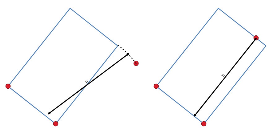
12.97. ábra Draw rectangle from 3 points using distance (right) and projected (left)
12.3.6.5. Draw Regular Polygons
There is a set of tools for drawing regular polygons. The tools are described below. Left-click to place the first point. A dialog appears, where you can set the number of polygon edges. Right-click to finish the regular polygon.
 Regular polygon from two points: Draws a regular
polygon where the two points determine the length and angle of the first edge.
Regular polygon from two points: Draws a regular
polygon where the two points determine the length and angle of the first edge. Regular polygon from center and a point:
Draws a regular polygon from the provided center point. The second point determines the
angle and distance to the middle of an edge.
Regular polygon from center and a point:
Draws a regular polygon from the provided center point. The second point determines the
angle and distance to the middle of an edge. Regular polygon from center and a corner:
Same as the preceding tool, but the second point determines the angle and
distante to a vertex.
Regular polygon from center and a corner:
Same as the preceding tool, but the second point determines the angle and
distante to a vertex.
12.3.7. The Advanced Digitizing panel
When capturing, reshaping, splitting new or existing geometries you also have the possibility to use the Advanced Digitizing panel. You can digitize lines exactly parallel or perpendicular to a particular angle or lock lines to specific angles. Furthermore, you can make a precise definition of your new geometry by entering X and Y coordinates as well as Z for 3D features, or M values.
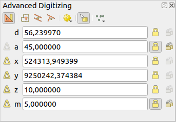
12.98. ábra The Advanced Digitizing panel
The Advanced Digitizing panel can be opened either with a right-click
on the toolbar, from menu or pressing
Ctrl+4. Once the panel is visible, click the Enable advanced
digitizing tools button to activate the set of tools.
Megjegyzés
The tools are not enabled if the map view is in geographic coordinates.
The aim of the Advanced Digitizing tool is to lock coordinates, lengths, and angles when moving the mouse during the digitizing in the map canvas.
You can also create constraints with relative or absolute reference. Relative reference means that the next vertex constraints» values will be relative to the previous vertex or segment.
12.3.7.1. The toolbar
At the top of the Digitizing panel, you find the following buttons:
- Enable advanced digitizing tools
 Construction mode: allows to capture the clicks»
positions to reuse as reference points to lock distance, angle, X, Y, Z or M
relative values. More details at Construction mode.
Construction mode: allows to capture the clicks»
positions to reuse as reference points to lock distance, angle, X, Y, Z or M
relative values. More details at Construction mode. Parallel to draw a line parallel to an existing one
(more at Parallel and perpendicular lines)
Parallel to draw a line parallel to an existing one
(more at Parallel and perpendicular lines) Perpendicular to draw a line perpendicular to an
existing one (more at Parallel and perpendicular lines)
Perpendicular to draw a line perpendicular to an
existing one (more at Parallel and perpendicular lines) Construction Tools provides a couple of options that
constrain the vertices placement based on extrapolated coordinates of
existing elements:
Construction Tools provides a couple of options that
constrain the vertices placement based on extrapolated coordinates of
existing elements:- Line Extension: hover over a segment and you get
a purple dotted line extending the segment across the map canvas.
You can snap the vertex anywhere on this virtual line.
- X/Y Point: hover over a vertex and you get
a purple dotted line along its X or Y coordinate, across the map canvas.
You can snap the vertex anywhere on this virtual line.
It is even possible to hover over two different vertices, generating virtual
coordinate lines for both, and snap to their intersection.
 2-circle Point Intersection: allows you to
digitize a point or vertex at the intersection of two circles.
(more at 2-circle point intersection).
2-circle Point Intersection: allows you to
digitize a point or vertex at the intersection of two circles.
(more at 2-circle point intersection).- Snap to common angles: when moving the cursor,
displays a virtual line that you can snap to to add the next vertex.
The snapping line is defined by the last added vertex
and an (absolute or relative to previous segment) angle from a preset list
(following steps of 0.1°, 0.5°, 1°, 5°, 10°, 15°, 18°, 22.5°, 30°, 45° or 90°).
Choose Do not snap to common angles to disable this feature.
Snapping to features can be used along with snapping to common angles for accurate digitizing. For a fine-grained control on how the target element to snap to is retained, you can indicate whether to prioritize snapping to features over common angles, and vice-versa under the Snapping priority entry. You can switch from one method to the other during the digitizing operation, and this avoids disabling any of the snapping options in the meantime. Press N (or Shift+N) during a digitizing operation to cycle through the angles list.
 Floater settings: if the Show floater item is checked,
a contextual menu with digitizing information follows the cursor during digitizing.
The values can be accessed using the panel’s shortcuts,
edited and Locked after validation (pressing Enter).
The type of information to display can be selected in the bottom part of the menu:
Floater settings: if the Show floater item is checked,
a contextual menu with digitizing information follows the cursor during digitizing.
The values can be accessed using the panel’s shortcuts,
edited and Locked after validation (pressing Enter).
The type of information to display can be selected in the bottom part of the menu:Show distance
Show angle
Show XY coordinates
Show Z value
Show M value
Show bearing/azimuth
Show common snapping angle
Below the toolbar, you will find a number of text boxes whose value reflects by default the position or movement of the cursor in the map canvas. Editing these values helps you constrain the position of the items you edit:
d for the distance from a reference position, usually the last edited vertex
a for the angle (absolute or relative) from a reference position, usually the last edited segment
x for the X coordinate of the pointer
y for the Y coordinate of the pointer
z for the default Z value or the Z coordinate of the vertex or segment under the pointer
m for the default M value or the M value of the vertex or segment under the pointer
12.3.7.2. Keyboard shortcuts
To speed up the use of Advanced Digitizing Panel, there are a couple of keyboard shortcuts available:
Key |
Simple |
Ctrl+ or Alt+ |
Shift+ |
|---|---|---|---|
D |
Set distance |
Lock distance |
|
A |
Set angle |
Lock angle |
Toggle relative angle to last segment |
X |
Set X coordinate |
Lock X coordinate |
Toggle relative X to last vertex |
Y |
Set Y coordinate |
Lock Y coordinate |
Toggle relative Y to last vertex |
Z |
Set Z coordinate |
Lock Z coordinate |
Toggle relative Z to last vertex |
M |
Set M value |
Lock M value |
Toggle relative M to last vertex |
C |
Toggle construction mode |
||
P |
Toggle perpendicular and parallel modes |
||
Megjegyzés
Z coordinate and M value options are available only if compatible with the layer geometry dimension.
12.3.7.3. Absolute reference digitizing
When drawing a new geometry from scratch, it is very useful to have the possibility to start digitizing vertices at given coordinates.
For example, to add a new feature to a polygonal layer, click the
button. You can enter the exact coordinates where you want
to start editing the feature, i.e.:
Click the x text box (or use the X keyboard shortcut).
Type the X coordinate value you want and press Enter or click the
button to their right to lock the mouse to the X axis on the map
canvas.Click the y text box (or use the Y keyboard shortcut).
Type the Y coordinate value you want and press Enter or click the
button to their right to lock the mouse to the Y axis on the map
canvas.If the layer has Z coordinate or M values, the corresponding z or m widget is enabled and displays its default value, as set in tab.
Click the z or m text box (or use respectively the Z or M keyboard shortcut).
Type the coordinate value you want and press Enter or click the
button to their right to lock the value in the widget.
Megjegyzés
Read Z koordináta és M érték hozzárendelésének szabályai for details on how Z coordinate and M values are automatically determined from existing features.
Two blue dotted lines and a green cross identify the exact coordinates you entered. Click on the map canvas to add a vertex at the green cross position.
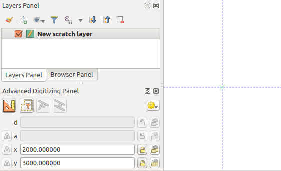
12.99. ábra Start drawing at given coordinates
You can proceed as above, adding a new set of coordinates for the next vertex, or switch to another mode of digitizing (e.g. segment, curve or stream).
If you want to draw a segment of a given length:
Click the d (distance) text box (keyboard shortcut D)
Type the distance value (in map units)
Press Enter or click the
button on the right to
lock the mouse in the map canvas to the length of the segment.
In the map canvas, the latest vertex is surrounded by a circle whose
radius is the value entered in the distance text box.
A cross on the circle shows the position of the next vertex if you click.
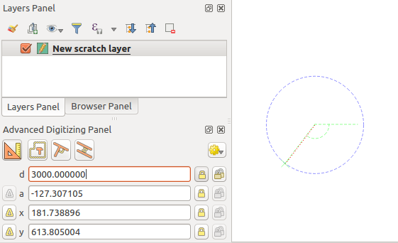
12.100. ábra Fixed length segment
You can also constrain the vertex position, setting the angle of the segment. As described before:
Click the a (angle) text box (keyboard shortcut A)
Type the angle value (in degrees)
Press Enter or click the
button on the right to lock it.
A line going through the latest vertex and rotated based on the set angle
appears in the map canvas and a cross on it shows the next vertex
position if you click.
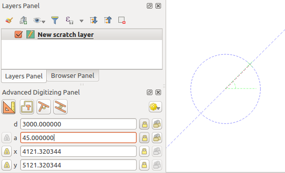
12.101. ábra Fixed angle segment
Tipp
Pressing Ctrl+<key> or Alt+<key> automatically locks
the target property and puts its value into edit. Modify, press Enter
and you are done. Combined with the Toggle floater,
this can be a real time saver, with keyboard digitizing.
12.3.7.4. Relative reference digitizing
Instead of using absolute values of angles or coordinates, you can also use values relative to the last digitized vertex or segment.
For angles, you can click the  button on the left of the a
text box (or press Shift+A) to toggle relative angles to the previous
segment. With that option on, angles are measured between the last segment
and the mouse pointer.
button on the left of the a
text box (or press Shift+A) to toggle relative angles to the previous
segment. With that option on, angles are measured between the last segment
and the mouse pointer.
For coordinates, click the buttons to the left of the x,
y, z or m text boxes (or press Shift+<key>)
to toggle relative coordinates to the previous vertex. With these options on,
coordinates measurement will consider the last vertex to be the origin of
the set coordinates.
12.3.7.5. Continuous lock
Both in absolute or relative reference digitizing, angle, distance, X, Y, Z
and M constraints can be locked continuously by clicking the  Continuous lock buttons. Using continuous lock allows you to
digitize several points or vertices using the same constraints.
Continuous lock buttons. Using continuous lock allows you to
digitize several points or vertices using the same constraints.
12.3.7.6. Construction mode
You can enable and disable construction mode by clicking on the
Construction mode icon or with the C keyboard
shortcut. While in construction mode, clicking the map canvas won’t add new
vertices, but will capture the clicks» positions so that you can use them as
reference points to then lock distance, angle or X, Y, Z, M relative values.
In the Construction mode you will find a drop-down menu
where you can choose to:
- Record Construction Guides: All construction steps are
rendered as dashed lines. Each step that you perform is visually represented,
allowing you to trace the construction process. The guides are displayed as
long as Advanced Digitizing remains active.
- Show Construction Guides: Allows you to make construction
guides visible or hidden on the canvas. When enabled, all active guides are displayed,
offering better spatial orientation and precision during the digitizing process.
- Snap to Visible Construction Guides: The guides are snap-able,
allowing you to start new construction steps from any point along the existing guides.
Choose Clear Construction Guides to remove all the guides from the canvas.
As an example, the construction mode can be used to draw some point at an exact distance from an existing point.
With an existing point in the map canvas and the snapping mode correctly
activated, you can easily draw other points at given distances and angles from
it. In addition to the button, you have to activate also the
construction mode by clicking the Construction mode
icon or with the C keyboard shortcut.
Click next to the point from which you want to calculate the distance and click on the d box (D shortcut) type the desired distance and press Enter to lock the mouse position in the map canvas:
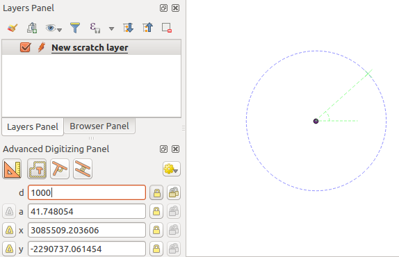
12.102. ábra Distance from point
Before adding the new point, press C to exit the construction mode. Now, you can click on the map canvas, and the point will be placed at the distance entered.
You can also use the angle constraint to, for example, create another point at
the same distance of the original one, but at a particular angle from the newly
added point. Click the Construction mode icon or with the
C keyboard shortcut to enter construction mode. Click the recently added
point, and then the other one to set a direction segment. Then, click on the
d text box (D shortcut) type the desired distance and press
Enter. Click the a text box (A shortcut) type the
angle you want and press Enter. The mouse position will be locked both in
distance and angle.
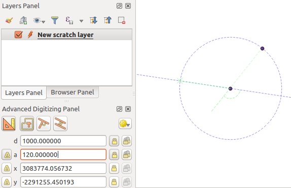
12.103. ábra Distance and angle from points
Before adding the new point, press C to exit the construction mode. Now, you can click on the map canvas, and the point will be placed at the distance and angle entered. Repeating the process, several points can be added.
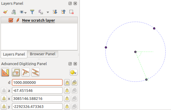
12.104. ábra Points at given distance and angle
12.3.7.7. Parallel and perpendicular lines
All the tools described above can be combined with the
Perpendicular and Parallel tools. These two tools
allow drawing segments perfectly perpendicular or parallel to another segment.
The target segment can be on another layer, another feature within the layer or
the feature being digitized (requires self-snapping option).
To draw a perpendicular segment:
First add one of the segment vertices.
Click the
Perpendicular icon
(keyboard shortcut P) to activate it.Click on the segment that you want to be perpendicular to.
A virtual dotted line perpendicular to the segment through the previous vertex appears. The angle property is locked, constraining the next vertex on that line and, a cross indicates the projected position of the cursor on the line. Click to place the new vertex.
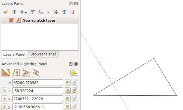
12.105. ábra Perpendicular digitizing
To draw a parallel segment, the steps are the same except that you need to
click on the Parallel icon (keyboard shortcut P twice).
12.106. ábra Parallel digitizing
These two tools just find the right angle of the perpendicular and parallel angle and lock this parameter during your editing. Unlock the angle parameter to cancel their use in the middle of the process.
12.3.7.8. 2-circle point intersection
To add a vertex at the intersection of two circles, follow these steps:
Click the
2-circle Point Intersection icon.A dialog will open where you can define the parameters for Circle #1 and Circle #2.
Click on the map canvas, and the tool will automatically calculate the X and Y coordinates for the centers of both circles.
Enter the distance d for each circle.
The tool will calculate and display the two intersection points of the circles.
Click one of the intersection points to add the new vertex.

12.107. ábra 2-circle Point Intersection
12.3.8. The Processing in-place layer modifier
The Processing menu provides access to a large set of tools to analyze and create new features based on the properties of the input features or their relations with other features (within the same layer or not). While the common behavior is to create new layers as outputs, some algorithms also allow modifications to the input layer. This is a handy way to automate multiple features modification using advanced and complex operations.
To edit features in-place:
Select the layer to edit in the Layers panel.
Select the concerned features. You can skip this step, in which case the modification will apply to the whole layer.
Press the
 Edit Features In-Place button at the top
of the Processing toolbox. The list of algorithms
is filtered, showing only those compatible with in-place modifications, i.e.:
Edit Features In-Place button at the top
of the Processing toolbox. The list of algorithms
is filtered, showing only those compatible with in-place modifications, i.e.:They work at the feature source and not at the layer level.
They do not change the layer structure, e.g. adding or removing fields.
They do not change the geometry type, e.g. from line to point layer.
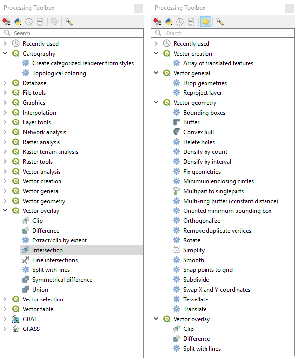
12.108. ábra Processing algorithms: all (left) vs polygon in-place editors (right)
Find the algorithm you’d like to run and double-click it.
Megjegyzés
If the algorithm does not need any additional user-set parameters (excluding the usual input and output layer parameters), then the algorithm is run immediately without any dialog popup.
If parameters other than the usual input or output layers are needed, the algorithm dialog pops up. Fill in the required information.
Click Modify Selected Features or Modify All Features depending on whether there’s an active selection.
Changes are applied to the layer and placed in the edit buffer: the layer is indeed toggled to editing mode with unsaved modification as indicated by the
 icon next to the layer name.
As usual, press
Save layer edits to commit the changes in
the layer. You can also press Undo to rollback the whole
modification.