Wichtig
Übersetzen ist eine Gemeinschaftsleistung Sie können mitmachen. Diese Seite ist aktuell zu 100.00% übersetzt.
16.4. Verbinden und Bearbeiten von Daten auf verschiedenen Layern
Die Fähigkeit, Daten aus verschiedenen Layern zu verbinden, ist eine der Aufgaben einer GIS-Software. Eine solche Verbindung kann auf der räumlichen Beziehung zwischen den Objekten oder auf ihren gemeinsamen Attributen beruhen. QGIS bietet Werkzeuge, um jede dieser Verbindungen zu handhaben, wie zum Beispiel:
Verarbeitungsalgorithmen, die als Ergebnis der Verbindung einen neuen Layer erzeugen können, nämlich Join attributes by location, Join attributes by nearest, Join attributes by field value, …
SQL-Abfragen zur Erstellung eines neuen Layers aus dem DB Manager oder als virtueller Layer
Verknüpfungseigenschaften oder Beziehungseinstellungen, die Attribute von Objekten in einem bestimmten Layer vorübergehend mit denen von Objekten in einem anderen Layer auf der Grundlage eines oder mehrerer übereinstimmender Attribute erweitern.
Verknüpfungen und Beziehungen sind technische Konzepte, die aus Datenbanken übernommen wurden, um die in Tabellen gespeicherten Daten durch die Kombination ihrer Inhalte optimal zu nutzen. Die Idee ist, dass Objekte (Zeilen) aus verschiedenen Layern (Tabellen) miteinander verbunden werden können. Die Anzahl der Zeilen, die miteinander übereinstimmen, kann einen beliebigen Wert haben (null, eins, viele).
16.4.1. Verknüpfung von Objekten zwischen zwei Layern
Verknüpfungen in QGIS erlauben es, Objekte des aktuellen Layers mit Objekten aus einem anderen geladenen Layer zu verknüpfen. Dabei spielt es keine Rolle, ob sie räumlich Daten enthalten und um welche Art von Geometrie es sich handelt. Die Verknüpfung basiert auf einem Attribut, das von den Layern in einer Eins-zu-Eins-Beziehung gemeinsam genutzt wird.
Um eine Verknüpfung auf einem Layer (im folgenden als Ziellayer bezeichnet) zu erstellen:
Klicken Sie auf die Schaltfläche
 Neue Verknüpfung hinzufügen. Der Dialog Vektorverknüpfung hinzufügen erscheint.
Wählen Sie unter Layer verknüpfen, den Layer aus, den Sie mit dem Ziellayer verbinden wollen
Geben Sie das Verknüpfungsfeld (aus
Layer verknüpfen) und das Zielfeld (aus demZiellayer) an. Diese Felder werden für die Suche nach übereinstimmenden Objekten in beiden Layern verwendet und sollten daher gemeinsame Werte haben.Drücken Sie OK und eine Zusammenfassung der ausgewählten Parameter wird auf dem Reiter Verknüpfungen hinzugefügt.
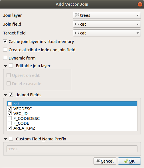
Abb. 16.101 Verknüpfe eine Attributtabelle zu einem vorhandenen Vektorlayer
Mit den obigen Schritten wird eine Verknüpfung erstellt, bei der alle Attribute des ersten übereinstimmenden Objekts im Layer der Verknüpfung zum Objekt des Ziellayers hinzugefügt werden. Die folgende Logik wird für die Paarung von Objekten während eines Verknüpfungsprozesses verwendet:
Alle Objekte im Ziellayer werden zurückgegeben, unabhängig davon, ob sie eine Übereinstimmung aufweisen
Wenn das Zielfeld doppelte Werte enthält, wird diesen Objekten dasselbe Objekt aus dem verknüpften Layer zugewiesen.
Wenn das Verknüpfungsfeld doppelte übereinstimmende Werte enthält, wird nur das erste abgefragte Objekt ausgewählt.
Bemerkung
Die Verknüpfungen in QGIS basieren auf einem Einzelfeldabgleich, so dass Sie in den meisten Fällen sicherstellen möchten, dass die Werte in den abgleichbaren Feldern eindeutig sind.
QGIS bietet einige weitere Optionen, um die Verknüpfung zu optimieren:
 Verknüpfung im Speicher cachen: ermöglicht das Zwischenspeichern von Werten im Speicher (ohne Geometrien) aus dem verbundenen Layer, um die Suchvorgänge zu beschleunigen.
 Attributindex auf Verknüpfungsfeld erzeugen um Suchvorgänge zu beschleunigen
 Dynamische Form: hilft, Verknüpfungsfelder laufend zu synchronisieren, entsprechend dem Zielfeld. Auf diese Weise werden auch die Beschränkungen („constrains“) für Verknüpfungsfelder korrekt aktualisiert. Beachten Sie, dass diese Funktion standardmäßig deaktiviert ist, da sie bei vielen Objekten oder zahlreichen Verknüpfungen sehr zeitaufwändig sein kann.
Wenn der Ziellayer bearbeitbar ist, werden in der Attributtabelle neben den Feldern einige Symbole angezeigt, um über ihren Status zu informieren:
 : Der Verknüpfungslayer ist nicht als bearbeitbar konfiguriert. Wenn Sie Verknüpfungs-Objekte in der Zielattributtabelle bearbeiten möchten, müssen Sie die Option
  Änderbarer verknüpfter Layer aktivieren.
 : Der Verknüpfungslayer ist so konfiguriert, dass er bearbeitet werden kann, aber sein aktueller Status ist nur lesbar.
 : Der Layer ist bearbeitbar, aber die Synchronisierungsmechanismen sind nicht aktiviert. Wenn Sie ein Objekt automatisch in den Join Layer einfügen wollen, wenn ein Objekt im Ziel Layer erstellt wird, dann müssen Sie die Option
  Einfügen/Aktualisieren bei Änderung aktivieren. Umgekehrt kann die Option
  Kaskadierendes Löschen aktiviert werden, wenn Sie Verknüpfungs-Objekte automatisch löschen wollen.
 Verknüpfte Felder: Anstatt alle Felder des verknüpften Layers hinzuzufügen, können Sie eine Teilmenge angeben.
 Benutzerfeldnamenpräfix für verbundene Felder, um Namenskollisionen zu vermeiden
16.4.2. Festlegung von Beziehungen zwischen mehreren Layern
Im Gegensatz zu Verknüpfungen, die eine Eins-zu-Eins-Verbindung zwischen Objekten auf zwei Layern definieren, können Sie mit Beziehungen Verbindungen zwischen mehreren Objekten auf zwei oder mehr Layern herstellen. Beziehungen sind Einstellungen auf Projektebene und werden unter  auf dem Reiter Beziehungen festgelegt. Von dort aus können Sie:
 Beziehung hinzufügen deren Typ sein kann:
polymorphe Beziehung die Sie mit den entsprechenden Werkzeugen im Dropdown-Menü der Aktion hinzufügen oder bearbeiten können.
Bemerkung
Es gibt noch keine einfache Möglichkeit, eine nicht polymorphe Beziehung zu bearbeiten, nachdem sie erstellt wurde. Nur der Name kann mit einem Doppelklick bearbeitet werden. Für alle anderen Parameter einer solchen Beziehung müssen Sie diese entfernen und neu erstellen.
 Beziehungen laden: QGIS ist in der Lage, bestehende Beziehungen aus unterstützten Datenbankformaten (PostgreSQL, GeoPackage, ESRI File Geodatabase, …) zu ermitteln. Dies kann eine gute Möglichkeit sein, die Definition von Beziehungen zu erleichtern.
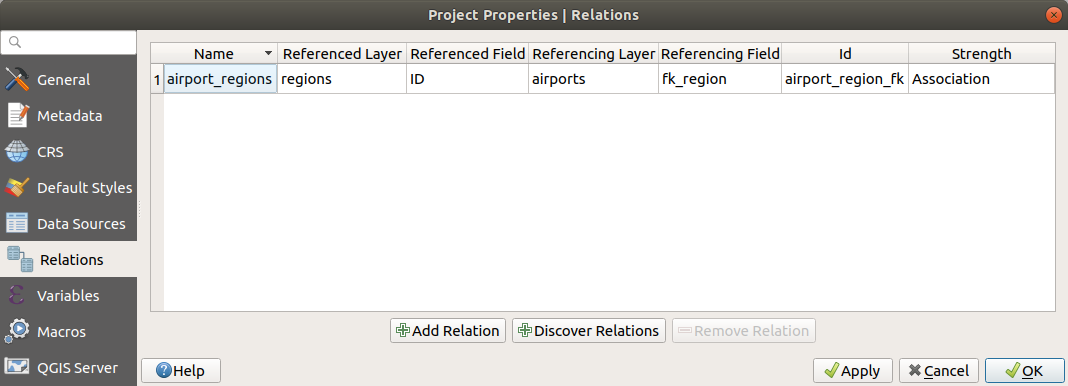
Abb. 16.102 Der Beziehungen Reiter
16.4.2.1. Eins-zu-viele-Beziehungen (1:n)
Als Beispiel haben Sie einen Layer mit allen Regionen Alaskas (Polygon), der einige Attribute über seinen Namen und Regionstyp sowie eine eindeutige ID (die als Primärschlüssel dient) enthält.
Dann erhalten Sie einen weiteren Layer oder eine Tabelle mit Informationen über Flughäfen, die sich in den Regionen befinden und die Sie ebenfalls verfolgen möchten. Wenn Sie diese zum Layer „Regionen“ hinzufügen möchten, müssen Sie eine Eins-zu-viele-Beziehung mit Fremdschlüsseln erstellen, da es in den meisten Regionen mehrere Flughäfen gibt.
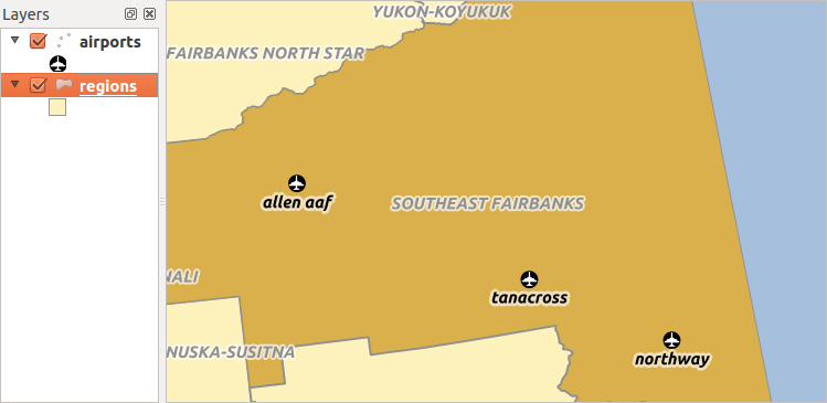
Abb. 16.103 Die Region Alaska mit Flughäfen
Layer und Schlüssel
QGIS macht keinen Unterschied zwischen einer Tabelle und einem Vektorlayer. Grundsätzlich ist ein Vektorlayer eine Tabelle mit einer Geometrie. Sie können also Ihre Tabelle als Vektorlayer hinzufügen. Um die 1:n-Beziehung zu demonstrieren, können Sie die Layer regions und airports aus den Beispieldatensatz laden. In der Praxis gehört jeder Flughafen zu genau einer Region, während jede Region eine beliebige Anzahl von Flughäfen haben kann (eine typische 1:n-Beziehung).
die ein Fremdschlüsselfeld (fk_region) zu den Regionen hat.
Zusätzlich zu den Attributen, die die Flughäfen beschreiben, hat der Layer aiports ein weiteres Feld fk_region, das als Fremdschlüssel fungiert (wenn Sie eine Datenbank haben, werden Sie wahrscheinlich eine Einschränkung für dieses Feld definieren wollen). Dieses fk_region-Feld enthält immer eine ID einer Region. Es kann als Zeiger auf die Region gesehen werden, zu der es gehört.
Alles, was Sie tun müssen, ist, QGIS die Beziehung zwischen den Layern mitzuteilen, damit Sie ein benutzerdefiniertes Formular für die Bearbeitung entwerfen können, und QGIS kümmert sich um die Einrichtung. Es ist auch möglich, verschiedenen Datenquellen in Beziehung zu setzen, Sie können also auch z.B. eine Shape-Datei und eine CSV-Datei verwenden.
Definieren von 1:n-Beziehungen
Als erstes müssen wir QGIS über die Beziehungen zwischen den Layern informieren. Dies geschieht unter . Öffnen Sie den Reiter Beziehungen und klicken Sie auf  Beziehung hinzufügen.
Name wird als Titel verwendet. Es sollte eine vom Menschen lesbare Zeichenfolge sein, die beschreibt, wofür die Beziehung verwendet wird. In diesem Fall nennen wir sie einfach airport_relation.
Referenziert (Elter), auch als Eltern-Layer bezeichnet, ist der Layer mit dem Primärschlüssel, auf den verwiesen wird, hier also der Layer
regions. Sie müssen den Primärschlüssel des referenzierten Layers definieren, in diesem Fall ist esID.Der Referenzierend (Kind), der auch als Kind-Layer bezeichnet wird, ist der Layer, auf dem sich das Fremdschlüsselfeld befindet. In unserem Fall ist dies der Layer
airports. Für diesen Layer müssen Sie ein referenzierendes Feld hinzufügen, das auf den anderen Layer verweist, alsofk_region.Bemerkung
Manchmal benötigen Sie mehr als ein einzelnes Feld, um Objekte in einem Layer eindeutig zu identifizieren. Das Erstellen einer Beziehung mit einem solchen Layer erfordert einen zusammengesetzten Schlüssel, d. h. mehr als ein einzelnes Paar übereinstimmender Felder. Verwenden Sie die Schaltfläche
 Neues Feldpaar als Teil eines zusammengesetzten Fremdschlüssels hinzufügen, um so viele Paare wie nötig hinzuzufügen.
Id wird für interne Zwecke verwendet und muss eindeutig sein. Sie benötigen sie möglicherweise, um Benutzerdefinierte Formulare zu erstellen. Wenn Sie sie leer lassen, wird eine für Sie generiert, aber Sie können selbst eine zuweisen, um eine einfacher zu handhabende zu erhalten
Beziehungsstärke legt die Stärke der Beziehung zwischen dem übergeordneten und dem untergeordneten Layer fest. Der Standardtyp Assoziation bedeutet, dass der übergeordnete Layer einfach mit dem untergeordneten Layer verknüpft ist, während der Typ Zusammenstellung es ermöglicht, beim Duplizieren des übergeordneten Layers auch die untergeordneten Objekte zu duplizieren und beim Löschen eines Objekts auch die untergeordneten Objekte zu löschen, was zu einer Kaskade über alle Ebenen führt (d.h. Kinder von Kindern von… werden ebenfalls gelöscht).
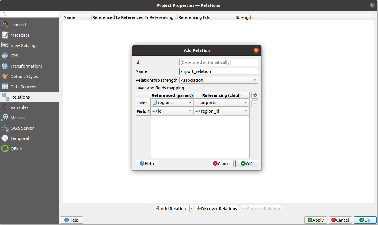
Abb. 16.104 Hinzufügen einer Beziehung zwischen den Layern regions und airports
Auf der Registerkarte Beziehungen können Sie auch auf die Schaltfläche  Beziehungen laden klicken, um die verfügbaren Beziehungen von den Providern der geladenen Layer abzurufen. Dies ist möglich für Layer, die in Datenprovidern wie PostgreSQL oder SpatiaLite gespeichert sind.
Formulare für 1:n-Beziehungen
Da QGIS nun über die Beziehung Bescheid weiß, werden in den entsprechenden Dialogen weitere Informationen angezeigt. Wenn z.B. die Standardmethode zur Erstellung des Objektformulars (automatisch generiert) nicht geändert wurde, wird einfach ein neuer Bereich in diesem Formular einfügt. Wählen Sie also den Layer regions in der Legende aus und verwenden das Objekte-abfragen-Werkzeug, um auf eine Region zu klicken, die mehrere Flughäfen enthält. Je nach Ihren Einstellungen wird das Formular direkt geöffnet oder Sie müssen es im Identifizierungsdialog unter Aktionen auswählen.
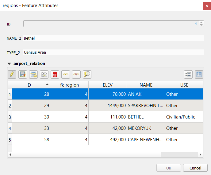
Abb. 16.105 Identifikationsergebnis-Dialog von einem Objekt aus dem Layer regions mit Beziehung zu airports
Wie Sie sehen können, werden die Flughäfen, die dieser Region zugeordnet sind, in einer Tabelle angezeigt. Außerdem gibt es einige Schaltflächen. Schauen wir sie uns kurz an:
Mit dem
 Knopf kann in den Bearbeitungsmodus umgeschaltet werden. Seien Sie sich bewusst, dass der Bearbeitungsmodus des ‚airports‘ Layers umschaltet wird, obwohl wir uns im Objektformular eines Objektes aus dem ‚regions‘ Layer befinden. Die Tabelle jedoch stellt Objekte des ‚aiports‘ Layer dar.
Mit der Schaltfläche
 werden alle Bearbeitungen im untergeordneten Layer (airports) gespeichert.
Mit der Schaltfläche
 können Sie die Flughafengeometrie in der Kartenansicht digitalisieren und das neue Objekt standardmäßig der aktuellen Region zuordnen. Beachten Sie, dass sich das Symbol je nach Geometrietyp ändert.
Die Schaltfläche
 fügt einen neuen Datensatz zur Attributtabelle des airports-Layers hinzu und weist das neue Objekt standardmäßig der aktuellen Region zu. Die Geometrie kann später mit dem Digitalisierwerkzeug Teil hinzufügen gezeichnet werden.
Mit der Schaltfläche
 können Sie ein oder mehrere untergeordnete Objekte innerhalb des untergeordneten Layers kopieren und einfügen. Sie können später einem anderen übergeordneten Objekt zugewiesen oder ihre Attribute geändert werden.
Die Schaltfläche
 löscht den/die ausgewählten Flughafen endgültig.
Das Symbol
 öffnet ein neues Dialogfeld, in dem Sie einen beliebigen bestehenden Flughafen auswählen können, der dann der aktuellen Region zugewiesen wird. Dies kann praktisch sein, wenn Sie den Flughafen versehentlich in der falschen Region angelegt haben.
Das Symbol
 hebt die Verknüpfung des/der ausgewählten Flughafens/Flughäfen mit der aktuellen Region auf, so dass sie nicht mehr zugewiesen sind (der Fremdschlüssel wird auf NULL gesetzt).
Mit der Schaltfläche
 können Sie die Karte auf die ausgewählten untergeordneten Objekte zoomen.
Die beiden Schaltflächen
 und
und  auf der rechten Seite schalten zwischen der Tabellenansicht und der Formularansicht der entsprechenden untergeordneten Objekte um.
Wenn Sie den Drag and Drop Designer 1 für das Objekt Regionen verwenden, können Sie auswählen, welche Werkzeuge verfügbar sind. Sie können sogar entscheiden, ob ein neues Formular geöffnet werden soll, wenn ein neues Objekt hinzugefügt wird, indem Sie die Option Formular beim Hinzufügen von Objekts verbergen verwenden. Seien Sie sich jedoch bewusst, dass diese Option voraussetzt, dass nicht-Null-Attribute automatisch ein gültiger Standardwert zugewiesen wird, damit sie den Vorgaben entsprechen.
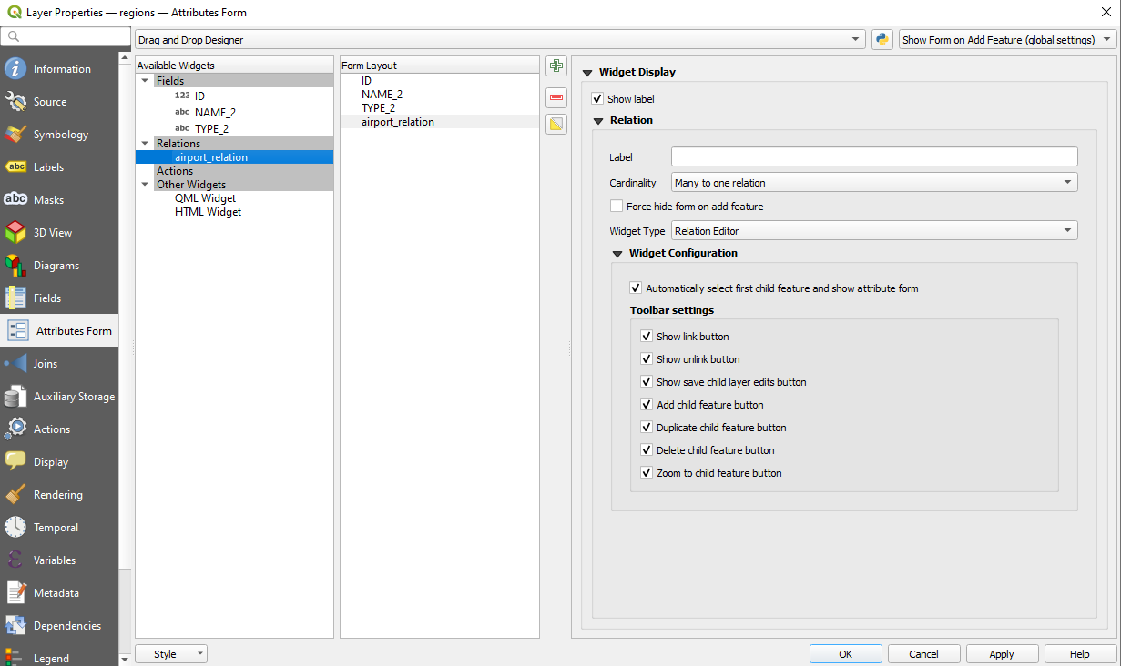
Abb. 16.106 Drag and Drop Designer für die Konfiguration der regions-airports-Beziehung
Im obigen Beispiel hat der referenzierende Layer Geometrien (es handelt sich also nicht nur um eine Tabelle), sodass die obigen Schritte einen Eintrag in der Layer-Attribut-Tabelle erzeugen, der kein entsprechendes geometrisches Objekt hat. So fügen Sie die Geometrie hinzu:
Wählen Sie den Datensatz aus, der zuvor im Objektformular des referenzierten Layers hinzugefügt wurde.
Verwenden Sie das Digitalisierungswerkzeug
 Teil hinzufügen, um eine Geometrie an den ausgewählten Datensatz der Attributtabelle anzuhängen.
Wenn Sie mit der Flughafentabelle arbeiten, wird das Widget Relation Reference automatisch für das Feld fk_region (das Feld, mit dem die Relation erstellt wurde) eingerichtet, siehe Relation Reference widget.
Im Formular des airports-Layers sehen Sie rechts neben dem Feld fk_region die Schaltfläche  : Wenn Sie auf die Schaltfläche klicken, wird das Formular des regions-Layers geöffnet. Mit diesem Widget können Sie einfach und schnell die Formulare der verknüpften übergeordneten Objekte öffnen.
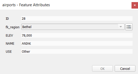
Abb. 16.107 Objekte abfragen Dialog von ‚airport‘ mit Beziehung zu ‚regions‘
Das Relation Reference Widget hat auch eine Option, um das Formular des übergeordneten Layers in den untergeordneten Layer einzubetten. Sie ist im Menü des airports-Layers verfügbar: Wählen Sie das Feld fk_region und aktivieren Sie die Option Eingebettetes Formular anzeigen.
Wenn Sie sich jetzt den Objektdialog ansehen, werden Sie sehen, dass das Formular für die Region in das Formular für die Flughäfen eingebettet ist und sogar eine Combobox enthält, mit der Sie den aktuellen Flughafen einer anderen Region zuweisen können.
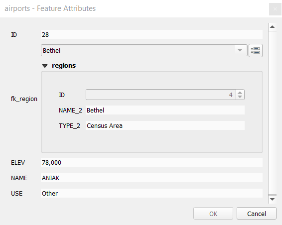
Wenn Sie den Editiermodus des airports-Layers umschalten, hat das Feld fk_region außerdem eine Autovervollständigungsfunktion: während der Eingabe sehen Sie alle Werte des Feldes id des regions-Layers. Hier ist es möglich, ein Polygon für den regions-Layer mit dem  Knopf zu digitalisieren, wenn Sie die Option
 Hinzufügen neuer Objekte erlauben im Menü des airports-Layers gewählt haben.
Der untergeordnete Layer kann auch im Werkzeug Objekte nach Wert auswählen verwendet werden, um Objekte des übergeordneten Layers anhand der Attribute der untergeordneten Layer auszuwählen.
In Abb. 16.108 werden alle Regionen ausgewählt, in denen die mittlere Höhe der Flughäfen mehr als 500 Meter über dem Meeresspiegel beträgt.
Sie werden feststellen, dass im Formular viele verschiedene Aggregationsfunktionen zur Verfügung stehen.
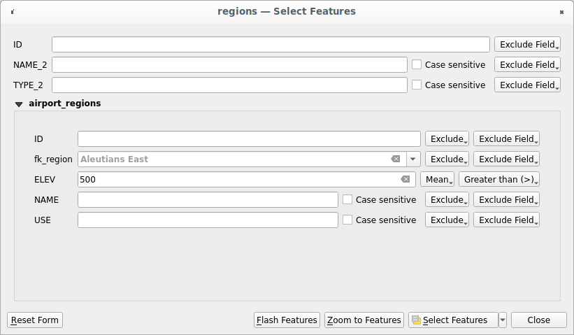
Abb. 16.108 Übergeordnete Objekte mit den Werten der untergeordneten Objekte auswählen
16.4.2.2. Viele-zu-viele-Beziehungen (n:m)
n:m-Beziehungen sind viele-zu-viele-Beziehungen zwischen zwei Tabellen. Zum Beispiel die Layer airports und airlines: an ein Flughafen landen mehrere Fluggesellschaften und eine Fluggesellschaft fliegt mehrere Flughäfen an.
Dieser SQL-Code erstellt die drei Tabellen, die wir für eine n:m-Beziehung in einem PostgreSQL/PostGIS-Schema namens locations benötigen. Sie können den Code mit der für PostGIS oder mit externen Tools wie pgAdmin ausführen. Die Flughafentabelle speichert den Layer airports und die Fluglinientabelle den Layer airlines. In beiden Tabellen werden aus Gründen der Übersichtlichkeit nur wenige Felder verwendet. Der schwierige Teil ist die airports_airlines Tabelle. Wir benötigen sie, um alle Fluggesellschaften für alle Flughäfen aufzulisten (oder umgekehrt). Diese Art von Tabelle ist als Pivot-Tabelle bekannt. Die Einschränkungen in dieser Tabelle erzwingen, dass ein Flughafen nur dann mit einer Fluggesellschaft verknüpft werden kann, wenn beide bereits in ihren Layern existieren.
CREATE SCHEMA locations;

CREATE TABLE locations.airports
(
   id serial NOT NULL,
   geom geometry(Point, 4326) NOT NULL,
   airport_name text NOT NULL,
   CONSTRAINT airports_pkey PRIMARY KEY (id)
);

CREATE INDEX airports_geom_idx ON locations.airports USING gist (geom);

CREATE TABLE locations.airlines
(
   id serial NOT NULL,
   geom geometry(Point, 4326) NOT NULL,
   airline_name text NOT NULL,
   CONSTRAINT airlines_pkey PRIMARY KEY (id)
);

CREATE INDEX airlines_geom_idx ON locations.airlines USING gist (geom);

CREATE TABLE locations.airports_airlines
(
   id serial NOT NULL,
   airport_fk integer NOT NULL,
   airline_fk integer NOT NULL,
   CONSTRAINT airports_airlines_pkey PRIMARY KEY (id),
   CONSTRAINT airports_airlines_airport_fk_fkey FOREIGN KEY (airport_fk)
      REFERENCES locations.airports (id)
      ON DELETE CASCADE
      ON UPDATE CASCADE
      DEFERRABLE INITIALLY DEFERRED,
   CONSTRAINT airports_airlines_airline_fk_fkey FOREIGN KEY (airline_fk)
      REFERENCES locations.airlines (id)
      ON DELETE CASCADE
      ON UPDATE CASCADE
      DEFERRABLE INITIALLY DEFERRED
 );
Anstelle von PostgreSQL können Sie auch GeoPackage verwenden. In diesem Fall können die drei Tabellen manuell über die erstellt werden. In GeoPackage gibt es keine Schemata, sodass das Präfix locations nicht benötigt wird.
Fremdschlüssel-Beschränkungen (constrains) in der Tabelle airports_airlines können nicht mit oder erstellt werden, daher sollten sie über erstellt werden. GeoPackage unterstützt keine ADD CONSTRAINT Anweisungen, daher sollte die Tabelle airports_airlines in zwei Schritten erstellt werden:
Richten Sie die Tabelle nur mit dem Feld
idein mitGeben Sie mit diesen SQL-Code ein und führen Sie ihn aus:
ALTER TABLE airports_airlines
   ADD COLUMN airport_fk INTEGER
   REFERENCES airports (id)
   ON DELETE CASCADE
   ON UPDATE CASCADE
   DEFERRABLE INITIALLY DEFERRED;

ALTER TABLE airports_airlines
   ADD COLUMN airline_fk INTEGER
   REFERENCES airlines (id)
   ON DELETE CASCADE
   ON UPDATE CASCADE
   DEFERRABLE INITIALLY DEFERRED;
Dann sollten Sie in QGIS zwei eins-zu-viele-Beziehungen einrichten, wie oben erklärt:
eine Beziehung zwischen der Tabelle
airlinesund der Pivot-Tabelle;und eine zweite zwischen der Tabelle
airportsund der Pivot-Tabelle.
Eine einfachere Methode (nur für PostgreSQL) ist die Verwendung des Discover Beziehungen laden in . QGIS wird automatisch alle Beziehungen in Ihrer Datenbank lesen und Sie müssen nur die zwei auswählen, die Sie benötigen. Denken Sie daran, die drei Tabellen zuerst in das QGIS-Projekt zu laden.
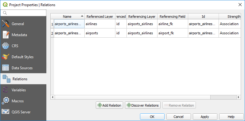
Abb. 16.109 Beziehungen laden
Falls Sie einen airport oder eine airline entfernen wollen, wird QGIS den/die zugehörigen Datensatz/-sätze in der Tabelle airports_airlines nicht entfernen. Diese Aufgabe wird von der Datenbank übernommen, wenn man die richtigen Einschränkungen bei der Erstellung der Pivot-Tabelle angibt, wie in diesem Beispiel.
Bemerkung
Kombinierte n:m-Beziehung mit automatischer Transaktionsgruppe
Sie sollten den Transaktionsmodus in aktivieren, wenn Sie in einem solchen Kontext arbeiten. QGIS sollte in der Lage sein, Zeilen in allen Tabellen (Fluggesellschaften, Flughäfen und den Pivot-Tabellen) hinzuzufügen oder zu aktualisieren.
Schließlich müssen wir unter für die Layer airports und airlines die richtige Kardinalität auswählen. Für den ersten Layer sollten wir die Option airlines (id) und für den zweiten die Option airports (id) wählen.
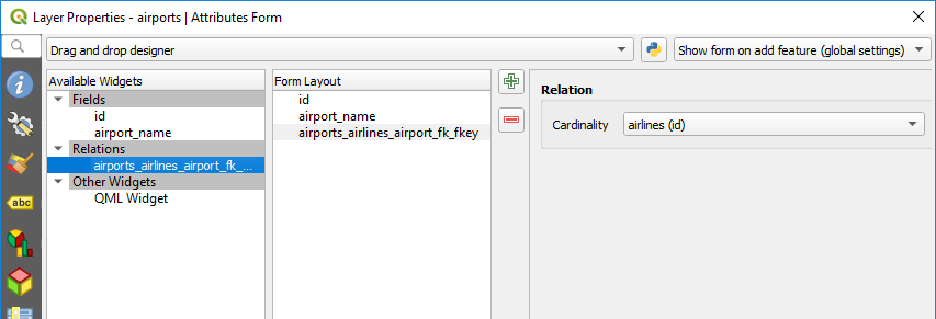
Abb. 16.110 Kardinalität der Beziehung festlegen
Jetzt können Sie einen Flughafen mit einer Fluggesellschaft (oder eine Fluggesellschaft mit einem Flughafen) verknüpfen, indem Sie Kind-Objekt hinzufügen oder Vorhandenes Kind-Objekt verknüpfen in den Unterformularen verwenden. Ein Datensatz wird automatisch in die Tabelle airports_airlines eingefügt.
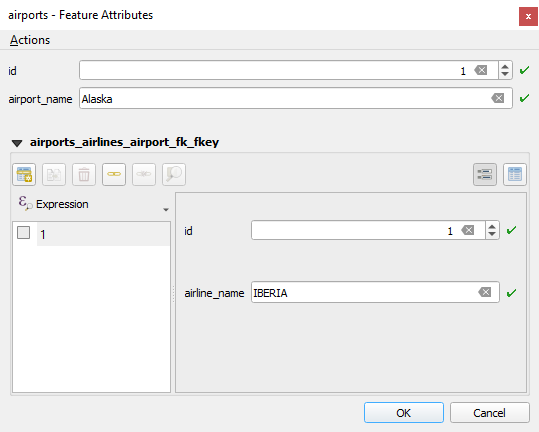
Abb. 16.111 n:m-Beziehung zwischen airports und airlines
Bemerkung
Verwendung der Kardinalität Viele-zu-eins-Beziehung
Manchmal ist es nicht wünschenswert, die Pivot-Tabelle in einer n:m-Beziehung auszublenden. Hauptsächlich deshalb, weil es in der Beziehung Attribute gibt, die nur dann Werte haben können, wenn eine Beziehung hergestellt ist. Wenn Ihre Tabellen ein Geometriefeld haben, könnte es interessant sein, die Option Auf der Karte auswählen zu aktivieren () für die Fremdschlüsselfelder in der Pivot-Tabelle.
Bemerkung
Pivot-Tabelle Primärschlüssel
Vermeiden Sie die Verwendung mehrerer Felder im Primärschlüssel einer Pivot-Tabelle. QGIS geht von einem einzigen Primärschlüssel aus, so dass eine Einschränkung wie constraint airports_airlines_pkey primary key (airport_fk, airline_fk) nicht funktionieren wird.
16.4.2.3. Polymorphe Beziehungen
Der Zweck
Polymorphe Beziehungen sind ein Spezialfall von 1:n-Beziehungen, bei denen ein einziger referenzierender Layer die Objekte für mehrere referenzierte Layer enthält. Dies unterscheidet sich von normalen Beziehungen, die für jeden referenzierten Layer einen anderen referenzierenden Layer erfordern. Ein einziger referenzierender Layer wird durch Hinzufügen einer zusätzlichen Spalte layer_field im referenzierenden Layer erreicht, die Informationen zur Identifizierung des referenzierten Layers enthält. In seiner einfachsten Form fügt der referenzierende Layer einfach den Layernamen des referenzierten Layers in dieses Feld ein.
Genauer gesagt ist eine polymorphe Beziehung eine Reihe normaler Beziehungen mit demselben referenzierenden Layer, wobei der referenzierte Layer dynamisch definiert ist. Die polymorphe Einstellung des Layers wird durch die Verwendung eines Ausdrucks gelöst, der mit einigen Eigenschaften des referenzierten Layers übereinstimmen muss, z. B. Tabellenname, Layer-ID, Layer-Name.
Stellen Sie sich vor, wir gehen in den Park und wollen Bilder von verschiedenen Arten von Pflanzen plants und Tieren animals machen, die wir dort sehen. Jeder Pflanze oder jedem Tier sind mehrere Bilder zugeordnet. Wenn wir also die normalen 1:n-Beziehung verwenden, um Bilder zu speichern, brauchen wir zwei separate Tabellen, animal_images und plant_images. Das mag für zwei Tabellen kein Problem sein, aber stellen Sie sich vor, wir wollen separate Bilder für Pilze, Vögel usw. aufnehmen.
Polymorphe Beziehungen lösen dieses Problem, da alle referenzierenden Objekte in derselben Tabelle documents gespeichert werden. Für jedes Objekt wird der referenzierte Layer im Feld referenced_layer und die referenzierte Objekt-ID im Feld referenced_fk gespeichert.
Eine polymorphe Beziehung definieren
Zunächst müssen Sie QGIS die polymorphen Beziehungen zwischen den Layern mitteilen. Dies geschieht unter . Öffnen Sie die Registerkarte Beziehungen und klicken Sie auf den kleinen Abwärtspfeil neben der Schaltfläche  Beziehung hinzufügen, sodass Sie die Option Polymorphe Beziehung hinzufügen aus dem neu erscheinenden Dropdown auswählen können.
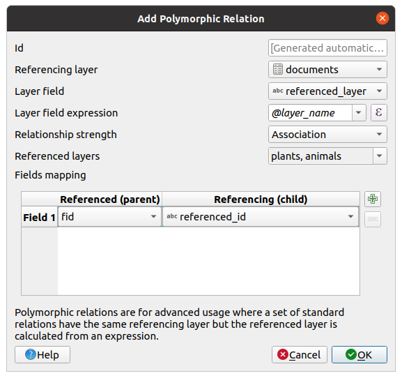
Abb. 16.112 Hinzufügen einer polymorphen Beziehung mit dem Layer documents als Referenz und den Layern animals und plants als referenzierte Layer.
Id wird für interne Zwecke verwendet und muss eindeutig sein. Sie benötigen sie möglicherweise, um Benutzerdefinierte Formulare zu erstellen. Wenn Sie sie leer lassen, wird eine für Sie generiert, aber Sie können selbst eine zuweisen, um eine einfacher zu handhabende zu erhalten
Der Referenzierender Layer, der auch als Kind-Layer bezeichnet wird, ist der Layer, in dem sich das Fremdschlüsselfeld befindet. In unserem Fall ist dies der Layer
documents. Für diesen Layer müssen Sie ein referenzierendes Feld hinzufügen, das auf den anderen Layer verweist, alsoreferenced_fk.Bemerkung
Manchmal benötigen Sie mehr als ein einzelnes Feld, um Objekte in einem Layer eindeutig zu identifizieren. Das Erstellen einer Beziehung mit einem solchen Layer erfordert einen zusammengesetzten Schlüssel, d. h. mehr als ein einzelnes Paar übereinstimmender Felder. Verwenden Sie die Schaltfläche
 Neues Feldpaar als Teil eines zusammengesetzten Fremdschlüssels hinzufügen, um so viele Paare wie nötig hinzuzufügen.
Layerfeld ist das Feld in der Referenztabelle, in dem das Ergebnis des ausgewerteten Layer-Ausdrucks gespeichert wird, d. h. die Referenztabelle, zu der dieses Objekt gehört. In unserem Beispiel wäre dies das Feld
referenced_layer.Layerfeldausdruck ergibt einen eindeutigen Bezeichner des Layers. Dies kann der Layer-Name
@layer_name, die Layer-ID@layer_id, der Tabellenname des Layersdecode_uri(@layer, 'table')oder etwas anderes sein, das einen Layer eindeutig identifiziert.Beziehungsstärke legt die Stärke der erzeugten Beziehungen zwischen dem übergeordneten und dem untergeordneten Layer fest. Der Standardtyp Assoziation bedeutet, dass der übergeordnete Layer einfach mit dem untergeordneten Layer verknüpft ist, während der Typ Zusammenstellung es ermöglicht, beim Duplizieren des übergeordneten Layers auch die untergeordneten Objekte zu duplizieren und beim Löschen eines Objekts auch die untergeordneten Objekte zu löschen, was zu einer Kaskade über alle Ebenen führt (d.h. Kinder von Kindern von… werden ebenfalls gelöscht).
Referenzierte Layer, die auch als übergeordnete Layer betrachtet werden, sind diejenigen, auf die der Primärschlüssel zeigt, in diesem Fall wären das die Layer
plantsundanimals. Sie müssen den Primärschlüssel der referenzierten Layer aus dem Dropdown-Menü definieren, hier ist esfid. Beachten Sie, dass die Definition eines gültigen Primärschlüssels voraussetzt, dass alle referenzierten Layer ein Feld mit diesem Namen haben. Wenn es kein solches Feld gibt, können Sie keine polymorphe Beziehung speichern.
Einmal hinzugefügt, kann die polymorphe Beziehung über den Menüeintrag Polymorphe Beziehung bearbeiten bearbeitet werden.
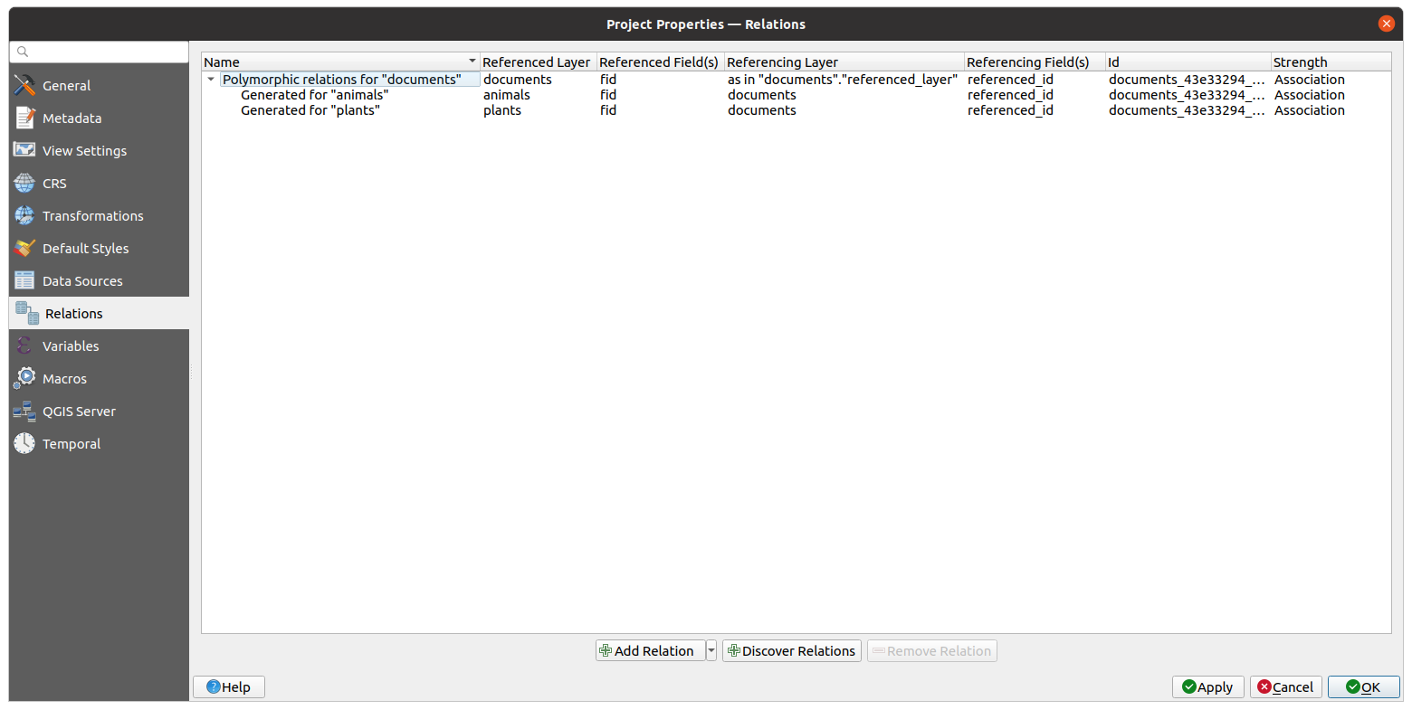
Abb. 16.113 Vorschau auf die neu erstellte polymorphe Beziehung und ihre untergeordneten Beziehungen für Tiere und Pflanzen.
Das oben genannte Beispiel verwendet das folgende Datenbankschema:
CREATE SCHEMA park;

CREATE TABLE park.animals
(
   fid serial NOT NULL,
   geom geometry(Point, 4326) NOT NULL,
   animal_species text NOT NULL,
   CONSTRAINT animals_pkey PRIMARY KEY (fid)
);

CREATE INDEX animals_geom_idx ON park.animals USING gist (geom);

CREATE TABLE park.plants
(
   fid serial NOT NULL,
   geom geometry(Point, 4326) NOT NULL,
   plant_species text NOT NULL,
   CONSTRAINT plants_pkey PRIMARY KEY (fid)
);

CREATE INDEX plants_geom_idx ON park.plants USING gist (geom);

CREATE TABLE park.documents
(
   fid serial NOT NULL,
   referenced_layer text NOT NULL,
   referenced_fk integer NOT NULL,
   image_filename text NOT NULL,
   CONSTRAINT documents_pkey PRIMARY KEY (fid)
);

