` `
レイヤーを作成する
Layers can be created in many ways, including:
- empty layers from scratch;
- layers from existing layers;
- layers from the clipboard;
- layers as a result of an SQL-like query based on one or many layers: the virtual layer.
QGIS also provides tools to import/export different formats.
Creating new vector layers
QGIS allows you to create new Shapefile layers, new SpatiaLite layers, new GPX layers and new Temporary Scratch layers. Creation of a new GRASS layer is supported within the GRASS plugin. (Please refer to section 新しいGRASSベクターレイヤーを作成する for more information on creating GRASS vector layers.)
新しいシェープファイルレイヤーを作成する
To create a new Shapefile layer, choose Create
Layer ‣  New Shapefile Layer... from the
Layer menu. The New Shapefile Layer dialog will be
displayed as shown in figure_create_shapefile. Choose the type of layer
(point, line or polygon) and the CRS (coordinate reference system).
New Shapefile Layer... from the
Layer menu. The New Shapefile Layer dialog will be
displayed as shown in figure_create_shapefile. Choose the type of layer
(point, line or polygon) and the CRS (coordinate reference system).
Note that QGIS does not yet support creation of 2.5D features (i.e., features with X,Y,Z coordinates).
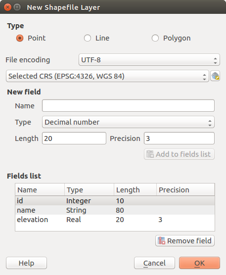
新しいシェープファイルレイヤーを作成するダイアログ
To complete the creation of the new Shapefile layer, add the desired attributes
by specifying a name and type for each attribute and clicking on the
[Add to fields list] button.
A first ‘id’ column is added by default but can be
removed, if not wanted. Only Decimal number  ,
Whole number , Text data
and Date attributes are
supported. Additionally, depending on the attribute type, you can also define
the length and precision of the new attribute column. Once you are happy with the
attributes, click [OK] and provide a name for the Shapefile. QGIS will
automatically add the .shp extension to the name you specify. Once the
Shapefile has been created, it will be added to the map as a new layer, and you can
edit it in the same way as described in section 既存レイヤーのデジタイズ.
,
Whole number , Text data
and Date attributes are
supported. Additionally, depending on the attribute type, you can also define
the length and precision of the new attribute column. Once you are happy with the
attributes, click [OK] and provide a name for the Shapefile. QGIS will
automatically add the .shp extension to the name you specify. Once the
Shapefile has been created, it will be added to the map as a new layer, and you can
edit it in the same way as described in section 既存レイヤーのデジタイズ.
新しいSpatiaLiteレイヤーを作成する
To create a new SpatiaLite layer for editing, choose New ‣
 New SpatiaLite Layer... from the
Layer menu. The New SpatiaLite Layer dialog will
be displayed as shown in Figure_create_spatialite.
New SpatiaLite Layer... from the
Layer menu. The New SpatiaLite Layer dialog will
be displayed as shown in Figure_create_spatialite.
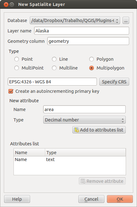
新SpatiaLiteレイヤーダイアログを作成する
The first step is to select an existing SpatiaLite database or to create a new
SpatiaLite database. This can be done with the browse button  to
the right of the database field. Then, add a name for the new layer, define
the layer type, and specify the coordinate reference system with [Specify CRS].
If desired, you can select
to
the right of the database field. Then, add a name for the new layer, define
the layer type, and specify the coordinate reference system with [Specify CRS].
If desired, you can select  Create an autoincrementing primary key.
To define an attribute table for the new SpatiaLite layer, add the names of the attribute columns you want to create with the corresponding column type, and click on the [Add to attribute list] button. Once you are happy with the attributes, click [OK]. QGIS will automatically add the new layer to the legend, and you can edit it in the same way as described in section 既存レイヤーのデジタイズ.
DBマネージャを使用するとSpatiaLiteレイヤーの高度な管理を実行できます。 DB マネージャプラグイン 参照。
Creating a new GeoPackage layer
To create a new GeoPackage layer go to Layer ‣ New ‣
 New GeoPackage Layer....
The New GeoPackage Layer dialog will
be displayed as shown in figure_create_geopackage.
New GeoPackage Layer....
The New GeoPackage Layer dialog will
be displayed as shown in figure_create_geopackage.
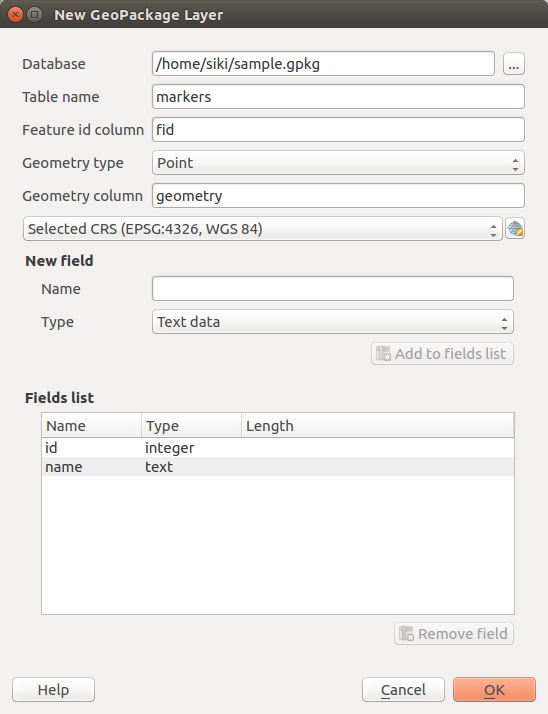
Creating a New GeoPackage layer dialog
The first step is to select an existing GeoPackage or create a new one. This can be done by pressing the ellipses [...] button at the right of the Database field. Then, give a name for the new layer, define the layer type and specify the coordinate reference system with [Specify CRS].
To define an attribute table for the new GeoPackage layer, add the names of the attribute columns you want to create with the corresponding column type, and click on the [Add to fields list] button. Once you are happy with the attributes, click [OK]. QGIS will automatically add the new layer to the legend, and you can edit it in the same way as described in section 既存レイヤーのデジタイズ.
新しいGPXレイヤーを作成する
新しいGPXファイルを作成するには、まずGPSプラグインをロードする必要があります。 プラグイン ‣  プラグインマネージャ... プラグインマネージャ]ダイアログが開きます。 GPSツール チェックボックスを有効にします。
When this plugin is loaded, choose New ‣  Create new GPX Layer... from the Layer menu.
In the Save new GPX file as dialog, choose where to save the
new file and press [Save]. Three new layers are added to the
Layers Panel: waypoints, routes and tracks with
predefined structure.
Create new GPX Layer... from the Layer menu.
In the Save new GPX file as dialog, choose where to save the
new file and press [Save]. Three new layers are added to the
Layers Panel: waypoints, routes and tracks with
predefined structure.
新しい一時的な落書きレイヤーを作成する
Temporary Scratch Layers are in-memory layers, meaning that they are not saved on disk and will be discarded when QGIS is closed. They can be handy to store features you temporarily need or as intermediate layers during geoprocessing operations.
Empty, editable temporary scratch layers can be defined using Layer ‣
Create Layer ‣ New Temporary Scratch Layer. Here you can create
 Multipoint, Multiline
and Multipolygon Layers beneath
Multipoint, Multiline
and Multipolygon Layers beneath
 Point, Line and
Polygon layers.
Point, Line and
Polygon layers.
You can also create Temporary Scratch Layers from the clipboard. See Creating new layers from the clipboard.
Creating new layers from an existing layer
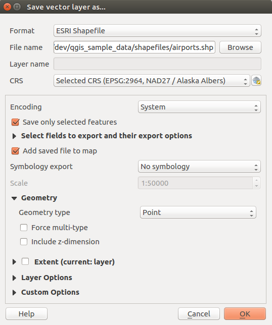
Both raster and vector layers can be saved in a different format and/or reprojected to a different coordinate reference system (CRS) using the Save As... function in the layer context menu (by right-clicking in the layer in the layer tree) or in the Layer ‣ Save As... menu.
一般的なパラメーター
The Save As dialog shows several parameters to change the behavior when saving the layer. Common parameters for raster and vector are:
- Format
ファイル名
- CRS can be changed to reproject the data
- Add saved file to map to add the new layer to the canvas
範囲 (可能な値は レイヤー 、 地図ビュー または ユーザー定義 範囲)
しかし、ラスター形式とベクター形式に固有のパラメーターもあります:
ラスター特定のパラメーター
出力モード (それができる 生データ または レンダリングされた画像 )
解像度
- Create Options: advanced options (file compression, block sizes, colorimetry...) to fine tune the output file. See the gdal-ogr driver documentation.
ピラミッド 作成
- VRT Tiles
データ値なし
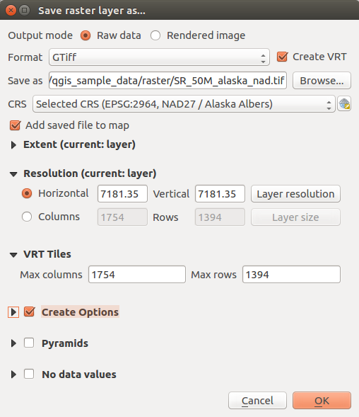
新しいラスターレイヤーとして保存する
ベクター固有のパラメーター
エクスポートの形式によっては、これらのオプションの一部が利用できますかどうか:
エンコード
選択地物のみ保存
エクスポートするフィールドとそのエクスポートオプションを選択 : 編集ウィジェット ケースでは、いくつかのフィールドの動作を設定します、例えば 値マップ 、チェックすることにより、レイヤー中に表示される値を保つことができます
値を表示 によって選択されたすべての生のフィールドの値を交換してください。シンボルをエクスポート :主にDXFのエクスポートのためと、DXF、KML、タブのファイル形式としてOGR地物のスタイル(下記の注を参照)を管理するすべてのファイル形式のために使用できます:
シンボルなし :データを読み込み、アプリケーションのデフォルトのスタイル
地物シンボル :OGR地物スタイルによるスタイルの保存(下記を参照)
シンボルレイヤーシンボル :OGR地物スタイルで保存(下記の注を参照)が、使用される複数のシンボルのシンボルレイヤーが存在する場合、同じジオメトリを複数回エクスポート
縮尺 値は、最新のオプションにも適用できます。
ノート
OGR Feature Styles are a way to store style directly in the data as a hidden attribute. Only some formats can handle this kind of information. KML, DXF and TAB file formats are such formats. For advanced users, you can read the OGR Feature Styles specification document.
ジオメトリ :出力レイヤーの幾何学的機能を設定できます
- geometry type: keep the original geometry of the features when set to Automatic, otherwise removes or overrides it with any type. You can add an empty geometry column to an attribute table, remove the geometry column of a spatial layer.
- Force multi-type: force creation of multi-geometry features in the layer
ジオメトリに Z次元を含める 。
ちなみに
Overriding layer geometry type makes it possible to do things like save a
geometryless table (e.g. .csv file) into a shapefile WITH any type of
geometry (point, line, polygon), so that geometries can then be manually added
to rows with the  Add Part tool .
- Datasources Options, Layer Options or Custom Options which allow you to configure some advanced parameters. See the gdal-ogr driver documentation.
新しいベクターレイヤーとして保存する
出力形式の能力(Geopackage、SpatiaLite、FileGDB ...)に応じて、既存のファイルへのベクターレイヤーを保存するとき、ユーザーは以下にするかどうかを決めることができます:
全体のファイルを上書き
ターゲットレイヤーだけを上書き(レイヤー名は設定可能です)
既存のターゲットレイヤーに地物を追加
地物を追加し、いずれかが存在する場合、新しいフィールドを追加します。
ESRIシェープファイル、のMapInfo .TABのような形式の場合、地物追記も可能です。
Creating new DXF files
Besides the Save As... dialog which provides options to export a single layer to another format, including *.DXF, QGIS provides another tool to export multiple layers as a single DXF layers. It’s accessible in the Project ‣ DXF Export... menu.
The DXF Export dialog allows the user to:
indicate the destination layer file;
choose the symbology mode and scale (see the OGR Feature Styles note);
select the encoding and CRS;
check the loaded layers to include in the DXF files or pick them from an existing visibility preset.
For each layer, you can choose a field whose values are used to split features in generated destination layers in the DXF output. You can also choose to
Use the layer title as name if set and keep features
grouped.choose to only Export features intersecting the current map extent.
Creating new layers from the clipboard
クリップボードにある地物は、新しいレイヤーに貼り付けできます。これを行うには、いくつかの地物を選択し、クリップボードにコピーし、 編集 ‣ 形式を選択して地物を貼り付け ‣ を使用して新しいレイヤーに貼り付け、以下を選択します:
- New Vector Layer...: you need to select the layer CRS, poping up the Save vector layer as... dialog from which you can select any supported data format (see Creating new layers from an existing layer for parameters);
- or Temporary Scratch Layer...: you need to select the layer CRS and give a name.
選択した地物とその属性で満たされた新しいレイヤーは、作成され、依頼された場合、地図キャンバスに追加されます。
ノート
Creating layers from clipboard applies to features selected and copied within QGIS and also to features from another source defined using well-known text (WKT).
Creating virtual layers
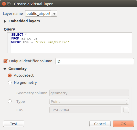
Virtual layers are a special kind of vector layer. They allow you to define a layer as the result of an SQL query involving any number of other vector layers that QGIS is able to open. Virtual layers do not carry data by themselves and can be seen as views to other layers.
To create a virtual layer, open the virtual layer creation dialog by clicking on Add Virtual Layer in the Layer menu or from the corresponding toolbar.
The dialog allows you to specify a Layer name and an SQL Query. The query can use the name (or id) of loaded vector layers as tables, as well as their field names as columns.
airports と呼ばれるレイヤーを持っている場合たとえば、次のようなSQLクエリで public_airports と呼ばれる新しい仮想レイヤーを作成できます。
SELECT *
FROM airports
WHERE USE = "Civilian/Public"
The SQL query will be executed, regardless of the underlying provider of the airports layer, even if this provider does not directly support SQL queries.
仮想レイヤーダイアログを作成します。
Joins and complex queries can also be created, for example, to join airports and country information:
SELECT airports.*, country.population
FROM airports
JOIN country
ON airports.country = country.name
ノート
DB マネージャプラグイン のSQLウィンドウを使用して仮想レイヤーを作成することも可能です。
Embedding layers for use in queries
地図キャンバスで利用可能なベクターレイヤーのほかに、ユーザーが 組み込みレイヤー リストにレイヤーを追加できます。それが地図キャンバスまたはレイヤーパネルに表示されていなくてもクエリで使用できます。
レイヤーを埋め込むには、 追加 をクリックし ローカル名 、 プロバイダー 、 エンコード および ソース へのパスを提供してください。
インポート ボタンが埋め込まれたレイヤーのリストに地図キャンバスにロードされたレイヤーを追加できます。これは、後に任意の既存のクエリを壊すことなく、レイヤーパネルからこれらのレイヤーを除去できます。
Supported query language
基本となるエンジンは動作するSQLiteのとSpatiaLiteを使用しています。
それはSQLiteのローカルインストールが理解SQLのすべてを使用できることを意味します。
SQLiteのとSpatiaLiteから空間関数から関数も仮想レイヤーのクエリで使用できます。例えば、属性のみのレイヤーのうちポイントレイヤーを作成することに類似したクエリを実行できます。
SELECT id, MakePoint(x, y, 4326) as geometry
FROM coordinates
QGIS式の関数 も仮想レイヤーのクエリ中で使用できます。
レイヤーのジオメトリ列を参照するため、名前 geometry を使用します。
純粋なSQLクエリに反して、仮想レイヤークエリのすべてのフィールドは名前を付ける必要があります。列が演算や関数呼び出しの結果である場合は、 as キーワードを使用してに名前を付けることを忘れないでください。
パフォーマンスの問題
デフォルトのパラメーターを設定すると、仮想レイヤーエンジンは1つが存在している場合はジオメトリ列の種類を含むクエリの異なる列の種類を検出するために最善を尽くします。
これは、可能な場合、クエリをイントロスペクトすることによって、または、最後にクエリ(LIMIT 1)の最初の行をフェッチすることによって行われます。ちょうどレイヤーを作成するために、結果の最初の行をフェッチすると、パフォーマンス上の理由で望ましくない場合があります。
作成ダイアログは、異なるパラメーターを指定できます:
一意の識別子列 :このオプションは、クエリのフィールドがQGISは、行識別子として使用できる一意の整数値を表すの指定を可能にします。デフォルトでは、自動増分の整数値が使用されます。一意の識別子列を定義すると、idによる行の選択を高速化できます。
ジオメトリなし :このオプションでは、任意のジオメトリフィールドを無視するように仮想レイヤーを強制します。得られるレイヤーは、属性のみのレイヤーです。
ジオメトリ 列 :このオプションでは、レイヤーのジオメトリとして使用される列の名前を指定できます。
ジオメトリ タイプ :このオプションでは、仮想レイヤーのジオメトリのタイプを指定できます。
ジオメトリ CRS :このオプションでは、仮想レイヤーの座標参照系を指定することを可能にします。
特別のコメント
仮想レイヤーエンジンは、クエリの各列のタイプを決定しようとします。それが失敗した場合、クエリの最初の行は、列の型を決定するためにフェッチされます。
特定の列の種類はいくつかの特別なコメントを使用することでクエリ中で直接指定できます。
構文は次のようです: /*:type*/ 。それはちょうど列の名前の後に配置する必要があります。 type は、整数の int 、浮動小数点数または text ための real のいずれかであり得ます。
例えば:
SELECT id+1 as nid /*:int*/
FROM table
ジオメトリ列の種類と座標参照系はまた、次の構文 /*:gtype:srid*/ を持つ特殊コメントのおかげで設定できます。ここで gtype はジオメトリタイプ( point 、 linestring 、 polygon 、 multipoint 、 multilinestring または multipolygon )であり srid は座標参照系のEPSGコードを表す整数です。
索引の使用
仮想レイヤーを介してレイヤーを要求するとき、このソースレイヤーの索引は次のように使用されるでしょう。
= 述語は、レイヤーの主キー列で使用される場合、基礎となるデータプロバイダーは、特定のID(FilterFid)を要求します
他の述語( > 、 <= 、 != など)または主キーのない列に対しては、式から構築された要求が基礎となるベクターデータプロバイダーを要求するために使用されます。それは、索引が存在する場合にそれらをデータベース・プロバイダーで使用できることを意味します。
具体的な構文が、リクエストで空間述語を処理し、空間索引の使用をトリガするために存在します: _search_frame_ という名前の非表示の列が各仮想レイヤーに対して存在します。この列はバウンディングボックスに等しいかどうかを比較できます。例:
SELECT *
FROM vtab
WHERE _search_frame_=BuildMbr(-2.10,49.38,-1.3,49.99,4326)
この空間索引の構文と組み合わせて使用する場合、 ST_Intersects のような空間バイナリ述語がかなり高速になっています。