` `
編集
QGISはOGR、SpatiaLite、PostGISに、MSSQL SpatialおよびOracle Spatialのベクターレイヤーとテーブルを編集するためのさまざまな機能をサポートしています。
ノート
GRASSレイヤーを編集する手順は異なります - 詳細は GRASSベクターレイヤーをデジタル化して編集する のセクションを参照。
ちなみに
同時編集
他の誰かが同じ時間に同じ地物を編集しているかどうかをQGISのこのバージョンでは追跡しません。その編集内容を保存するには、最後の人が勝ち。
スナップ許容誤差と検索半径の設定
ベクターレイヤーの形状の最適かつ正確な編集のために、地物の頂点のスナップの誤差と検索半径の適切な値を設定する必要があります。
スナップ許容誤差
スナップ許容誤差とは、QGISは新しい頂点を設定するときに接続するか、既存の頂点を移動しようとしている最も近い頂点および/またはセグメントの 検索 に使用する距離です。スナップ許容範囲内にない場合は、QGISではなく、既存の頂点および/またはセグメントにそれを合わせる、マウスボタンを放し頂点を残すだろう。スナップ許容誤差の設定が許容誤差で動作するすべてのツールに影響します。
一般的な、プロジェクト全体のスナップ許容誤差は 設定 ‣
 オプション... デジタル化 タブを選択することによって定義できます。デフォルトのスナップモードとして「頂点およびセグメントに」または「セグメントに」、「頂点に」の間を選択できます。また、デフォルトスナップ許容誤差と頂点の編集のための検索半径を定義できます。許容誤差は、地図単位またはピクセルのいずれかに設定できます。ピクセルを選択する利点は、ズーム操作の後にスナップ許容誤差を変更する必要がないことです。(アラスカデータセットを扱う)私たちの小さなデジタル化プロジェクトでは、フィートのスナップ単位を定義します。結果は異なる場合がありますが、1:10000の縮尺で300フィートのために何かは、合理的に設定する必要があります。
- A layer-based snapping tolerance that overrides the global snapping options
can be defined by choosing Settings ‣ Snapping options.
It enables and adjusts snapping mode
and tolerance on a layer basis (see figure_edit_snapping ). This dialog offers
three different modes to select the layer(s) to snap to:
現在レイヤー :アクティブなレイヤーだけが使用されます、レイヤー内のトポロジが編集されることを確実にする便利な方法です
すべてのレイヤー :プロジェクト内のすべての可視レイヤーのための迅速かつ簡単な設定ポインタはすべての頂点および/またはセグメントに収まるようになっています。ほとんどの場合、このスナップモードを使用すれば十分です。
高度な :レイヤーを編集し、別のレイヤーにその頂点をスナップ、ターゲットレイヤーが確認されていることを確認し、より大きな値にスナップ許容値を増やす必要がある場合。さらに、スナップは関係なく、グローバルなスナップ許容値の、スナップオプション]ダイアログボックスでチェックされていないレイヤーに発生することはありません。ですからにスナップする必要がこれらのレイヤーのチェックボックスをマークしてください。
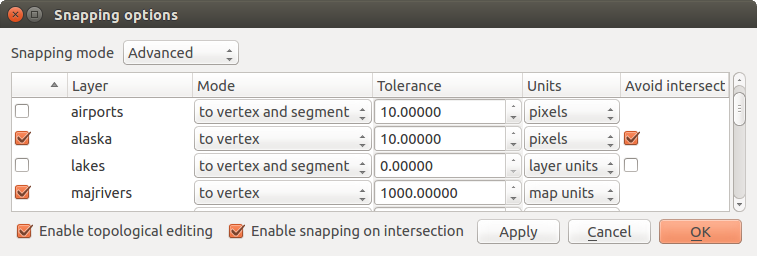
レイヤー単位での編集スナップオプション(高度なモード)
ちなみに
スナップするレイヤーのリストを制御
スナップオプション ダイアログにはデフォルトでグローバル デジタル化 タブに設定されたパラメーター(モード、許容誤差、単位)が入っています。 高度な モードでデフォルトでレイヤーがチェックされる、したがってスナップ可能に設定されるのを避けるには、 デフォルトのスナップモード を Off に定義してください。
スナップ許容誤差は ピクセル または 地図単位 (地図ビューの単位)で設定できます。 高度な レイヤー選択モードでは、 レイヤー単位 、「その場で」CRS変換が有効なとき再投影レイヤーの単位、を指すスナップ許容誤差を使用することが可能です。
検索半径
Search radius is the distance QGIS uses to search for the closest vertex
you are trying to select when you click on the map. If you aren’t within the
search radius, QGIS won’t find and select any vertex for editing.
The search radius for vertex edits can be defined under Settings ‣
Options ‣ Digitizing tab. This is the same
place where you define the general, project-wide snapping tolerance.
Snap tolerance and search radius are set in map units or pixels, so you may find you need to experiment to get them set right. If you specify too big of a tolerance, QGIS may snap to the wrong vertex, especially if you are dealing with a large number of vertices in close proximity. Set search radius too small, and it won’t find anything to move.
トポロジ編集
設定 (または ファイル )メニューの オプションをスナップ... ダイアログレイヤーベースのスナップオプションに加えて、またトポロジ的な機能を定義できます。ここでは、  トポロジの編集を有効にする を定義、および/または、ポリゴンのレイヤーについて 交差を回避 オプションを有効にできます。
トポロジ編集を有効にする
オプション トポロジの編集を有効 は、地物のモザイク中で共通の境界を編集および維持するためです。QGISは地物によって共有される境界を「検出」し、共通の頂点/セグメントを移動する必要は一度だけであり、QGISは隣接する地物を更新する世話をします。
新規ポリゴンの重なりの禁止
交差を避ける と呼ばれる2つめのトポロジ的オプションは、既存のものと重複する新しい地物を描画できないようにします。これは、隣接するポリゴンを迅速にデジタル化するためです。既に1つ目のポリゴンを使用している場合は、このオプションにより、両方が交差するように2つ目をデジタル化すると、QGISでは既存の1つ目の境界に2つ目のポリゴンをカットすることが可能です。利点は、共通の境界のすべての頂点をデジタル化する必要がないことです。
ノート
新しいジオメトリが完全に既存のもので覆われている場合は、それがクリアされますと、新しい地物では、それ以外の変更を保存し、プロバイダーによって許可された何のジオメトリを持ちませんQGISポップアップエラーメッセージになります。
警告
交差を回避 オプション は 慎重に使用 してください
オプションのカットまたは任意のポリゴンレイヤーからの任意の重なるoverlaping地物のジオメトリをクリアしているので、もはやそうでない場合、それを必要とすると、予期しないジオメトリを得ることができ、このオプションをオフにすることを忘れないでください。
交差に対するスナッピングを有効にする
交差部でスナップを有効にする という別のオプションがあります。これを利用すると背景図レイヤーとの交差にスナップできます。その場合交差部に頂点がなくてもスナップ可能です。
ジオメトリチェッカー
コアプラグインはジオメトリ無効を見つけるためにユーザーを助けることができます。このプラグインの詳細情報は ジオメトリチェッカープラグイン に見つかります。
既存レイヤーのデジタイズ
デフォルトでは、QGISはレイヤーを読み取り専用でロードします。これは、マウスが滑ってしまった場合に誤ってレイヤーを編集することを避けるための安全装置です。しかし、どんなレイヤーでも、データプロバイダーがサポートしていて( データフォーマットとフィールドを書き出す 参照)かつ基礎となるデータソースが書き込み可能である(すなわち、そのファイルが読み取り専用でない)限り、編集を選択できます。
ちなみに
プロジェクト内のレイヤーに対する編集権限を制限する
From the Project ‣ Project properties ‣ Identify tab, You can choose to set any layer read-only regardless the provider permission. This can be a handy way, in a multi-users environment to avoid unauthorized users to mistakenly edit layers (e.g., shapefile), hence potentially corrupt data. Note that this setting only applies inside the current project.
ベクターレイヤーを編集するツールは、デジタイズと高度なデジタイズという二つのツールバーにわけてまとめられています。高度なデジタイズについては 高度なデジタイジング によって解説されています。 このツールの選択/非選択は ビュー ‣ ツールバー ‣ によって行います。基本的なデジタイズのツールでは次のような機能を使用できます。
アイコン |
目的 |
アイコン |
目的 |
|---|---|---|---|
 |
現在の編集 |
 |
編集切り替え |
 |
地物を追加:ポイントをキャプチャ |
 |
地物を追加:ラインをキャプチャ |
 |
地物を追加:ポリゴンをキャプチャ |
 |
Move Feature |
 |
Add Circular String |  |
Add Circular String By Radius |
 |
Node Tool |  |
選択したものの削除 |
 |
地物の切り取り |
 |
地物のコピー |
 |
地物の貼り付け |
 |
レイヤー編集の保存 |
テーブル編集:ベクターレイヤー基本編集ツールバー
デジタル化のツールを何か使用している間も、ツールにフォーカスを失うことなく地図キャンバス内で ズームやパン ができることに注意してください。
すべての編集セッションは所定のレイヤーのコンテキストメニューにある 編集切替 オプション選択することによって開始、属性テーブル]ダイアログ、デジタル化のツールバー、または 編集 メニューボックスから。
レイヤーが編集モードになると、編集ツールバー上に追加のツールボタンが利用可能になり、マーカーは 設定 ‣ オプション... ‣ デジタル化 メニュー下 選択した地物だけにマーカー表示 オプションがチェックされない限り、すべての地物の頂点に表示されます。
ちなみに
定期的に保存する
定期的に レイヤー編集を保存 することを忘れないでください。また、これはデータソースがすべての変更を受け入れることができることを確認します。
地物を追加する
You can use the Add Feature,
Add Feature or
Add Feature icons on the toolbar to add new feature (point, line and
polygon) into the current layer.
The next buttons Add circular string or
Add circular string by radius allow users to add
line or polygon features with a circular geometry.
To create features with these tools, you first digitize the geometry then enter its attributes. To digitize the geometry, left-click on the map area to create the first point of your new feature.
For linear or curved geometries, keep on left-clicking for each additional point you wish to capture or use automatic tracing capability to accelerate the digitization. You can switch back and forth between linear Add feature tool and curved Add circular string... tools to create compound curved geometry. Pressing Delete or Backspace key reverts the last node you add. When you have finished adding points, right-click anywhere on the map area to confirm you have finished entering the geometry of that feature.
ノート
湾曲形状は互換性のあるデータプロバイダーにおいてだけそのようなものとして記憶
Although QGIS allows to digitize curved geometries within any editable data format, you need to be using a data provider (e.g. PostGIS, GML or WFS) that supports curves to have features stored as curved, otherwise QGIS segmentizes the circular arcs. The memory layer provider also supports curves.
ちなみに
デジタル化ゴムバンドをカスタマイズ
ポリゴンをキャプチャしながら、デフォルトの赤いゴムバンドを使用すると、ポイントをキャプチャしたいのですが、基礎となる地物や場所を非表示にできます。 設定 ‣ オプション ‣ デジタル化 メニュー内の 塗りつぶし色 このゴムバンドの下に不透明度(またはアルファチャンネル)を設定することによって固定できます。 ノード編集中にゴムバンドを更新しない をチェックすることにより、ゴムバンドの使用を避けることもできます。
属性ウィンドウが表示され、新しい地物のための情報を入力できます。 Figure_edit_values は、アラスカの架空の新しい川の属性を設定することを示しています。しかし、 設定 ‣ オプション メニュー下の デジタル化 メニューの中で、以下もアクティブにできます。
- Suppress attributes pop-up windows after each created
feature to avoid the form opening
または
最後に入力された属性値を再利用 で、フォームが開いたときにフィールドが自動的に満たされ変化する値を入力する必要があるだけにします。
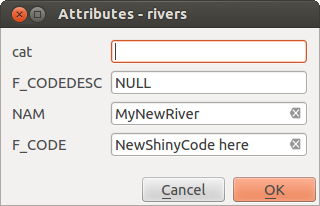
属性を入力すると、新しいベクター地物をデジタル化した後、ダイアログ値
With the Move Feature(s) icon on the toolbar, you can
move existing features.
Node Tool
For shapefile-based or MapInfo layers as well as SpatiaLite, PostgreSQL/PostGIS,
MSSQL Spatial, and Oracle Spatial tables, the
Node Tool provides manipulation capabilities of
feature vertices similar to CAD programs. It is possible to simply select
multiple vertices at once and to move, add or delete them altogether.
The node tool also works with ‘on the fly’ projection turned on and supports
the topological editing feature. This tool is, unlike other tools in
QGIS, persistent, so when some operation is done, selection stays
active for this feature and tool.
プロパティ 設定 ‣ オプション ‣ デジタル化 ‣ 検索半径:  をゼロより大きい数に設定することが重要です。そうでない場合は、QGISではどの頂点が編集されているか伝えることができなくなり、警告が表示されます。
ちなみに
頂点マーカー
「半透明の円」、「十字架」と「なし」:QGISの現在のバージョンは、頂点マーカーの3種類をサポートしています。マーカーのスタイルを変更するには 設定 メニューから オプション 選択し、 デジタル化 タブをクリックして、適切なエントリを選択します。
基本操作
Start by activating the Node Tool and selecting a
feature by clicking on it. Red boxes will appear at each vertex of this feature.
- Selecting vertices: You can select vertices by clicking on them one at a time, by clicking on an edge to select the vertices at both ends, or by clicking and dragging a rectangle around some vertices. When a vertex is selected, its color changes to blue. To add more vertices to the current selection, hold down the Ctrl key while clicking. Hold down Ctrl when clicking to toggle the selection state of vertices (vertices that are currently unselected will be selected as usual, but also vertices that are already selected will become unselected).
- Adding vertices: To add a vertex, simply double click near an edge and a new vertex will appear on the edge near to the cursor. Note that the vertex will appear on the edge, not at the cursor position; therefore, it should be moved if necessary.
頂点を削除する:頂点を選択し、クリックしてください DELETE キーを。地物のすべての頂点を削除すると、データソースと互換性がある場合は、ジオメトリなし地物が作成されます。これは、完全に地物を削除せず、ジオメトリ部分だけを削除することに注意してください。完全に地物を削除するには、
選択を削除 ツールを使用します。- Moving vertices: Select all the vertices you want to move, click on a selected vertex or edge and drag in the direction you wish to move. All the selected vertices will move together. If snapping is enabled, the whole selection can jump to the nearest vertex or line.
Each change made with the node tool is stored as a separate entry in the Undo dialog. Remember that all operations support topological editing when this is turned on. On-the-fly projection is also supported, and the node tool provides tooltips to identify a vertex by hovering the pointer over it.
ちなみに
Move features with precision
The Move Feature tool doesn’t currently allow to
snap features while moving. Using the Node Tool, select ALL
the vertices of the feature, click a vertex, drag and snap it to a target vertex:
the whole feature is moved and snapped to the other feature.
The Vertex Editor
With activating the Node Tool on a feature, QGIS opens the Vertex Editor panel listing all the vertices of the feature with their x, y (z, m if applicable) coordinates and r (for the radius, in case of circular geometry). Simply select a row in the table does select the corresponding vertex in the map canvas, and vice versa. Simply change a coordinate in the table and your vertex position is updated. You can also select multiple rows and delete them altogether.
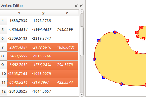
選択したノードを示す頂点エディタパネル
地物の切り取り、コピーと貼り付け
選択した地物が、同じQGISプロジェクトのレイヤーの間に、カット、コピー&ペーストできる限り、先のレイヤーが設定されているように事前に 編集切り替え 。
ちなみに
コピー/ペーストを使用して行およびその逆にポリゴンを変換
ポリゴンレイヤーにライン地物をコピーして貼り付け:QGISでは貼り付け先レイヤーにその境界、ライン地物の閉じた形状に対応したポリゴンを貼り付けます。これは、同じデータの異なる形状を生成する簡単な方法です。
地物はテキストなどの外部アプリケーションに貼り付けできます。これは、地物はジオメトリデータはOGC well-knownテキスト(WKT)形式に登場すると、CSV形式で表現されています。外部QGISからのWKTおよびGeoJSON地物もQGIS内のレイヤーに貼り付けできます。
どんなときであればコピー&ペースト機能が便利になるのでしょうか?まあ、それはあなたがレイヤーの間の一度にコピー/貼り付け機能で複数のレイヤーを編集できることが判明しました。なぜ我々はこれをしたいのでしょうか?私たちは big_lakes レイヤーの上に5000、ない新しいレイヤーの上にいくつかの作業を行う必要があるが、1つのまたは2つの湖を必要とします。新しいレイヤーを作成し、コピー/貼り付けを使用して必要な湖をそこにポトンと落とすことができます。
例として新しいレイヤーにいくつかの湖沼をコピーします:
コピーしたいレイヤーをロードします (元レイヤー)
コピー先にしたいレイヤーをロードまたは作成します(先レイヤー)
先レイヤーの編集を開始します
凡例をクリックして元レイヤーをアクティブにします
 領域またはシングルクリックで地物を選択 ツールを使用して、ソースレイヤー上の地物(複数可)を選択します
- 地物をコピー ツールをクリックして
凡例をクリックしてコピー先レイヤーをアクティブにします
- 地物を貼り付け ツールをクリックして
編集モードを終了して変更内容を保存して下さい
コピー元とコピー先レイヤーでスキーマが異なる(フィールド名とタイプが同じではない)場合はどうなりますか?QGISは一致するものを投入し、残りは無視します。コピー先レイヤーにコピーされる属性は気にしないのであれば、フィールドとデータ型を設計する方法は重要ではありません。すべて、つまり地物とその属性、が必ずコピーされるようにしたい場合は、スキーマが一致していることを確認してください。
ノート
貼り付け地物の一致
コピー元とコピー先のレイヤーが同じ投影を使用する場合は、貼り付けられた地物はソースレイヤーと同一の形状になるでしょう。しかし、コピー先のレイヤーの投影が異なる場合、QGISでは形状が同一であることを保証できません。これは単に、投影間で変換する時に小さな丸め誤差が入ってくるためです。
ちなみに
文字列属性を他にコピー
タイプ「文字列」を使用して属性テーブルに新しい列を作成し、より大きな長さを持つ別の属性列から値を貼り付けたい場合、列のサイズの長さは同じ量に拡張されるでしょう。GDAL / OGR 1.10始まるGDALシェープファイルドライバが動的に挿入されるデータの長さに適応するように、文字列と整数フィールドを自動的に拡張することを知っているからです。
選択地物の削除
地物全体(属性とジオメトリ)を削除したい場合は、正規 エリアやシングルクリックで地物を選択 ツールを使用して最初にジオメトリを選択することによって行うことができます。選択は属性テーブルからも行うことができます。選択セットを得たら、 DELETE か Backspace キーを押すか、または 選択を削除 ツールを使用して地物を削除します。選択した複数の地物を一度に削除できます。
デジタル化ツールバーの 地物を切り取り ツールは、地物を削除するために使用できます。これは効果的に地物が削除されますが、それらをまた「空間クリップボード」上に置きます。そこで、削除する地物をカット。その後、 地物を貼り付け ツールを使用できます、1レベルの取り消し機能を与え、それを戻すために。一度に複数の上で動作させることができることを意味し、現在選択されている地物の切り取り、コピー、貼り付け作業。
編集レイヤーの保存
レイヤーが編集モードである場合、すべての変更は、QGISのメモリに残ります。したがって、それらはすぐにデータソースまたはディスクにコミット/保存されるわけではありません。現在のレイヤーに編集内容を保存したいが、編集モードを離れることなく、編集を続けたい場合は、クリックできます レイヤー編集を保存 ボタン。 編集を切り替え で編集モードを無効にする(またはそのことについてQGISを終了する)と、変更を保存するか破棄するか尋ねられます。
変更が保存できない場合(例えば、ディスクがいっぱい、または属性が範囲外の値を持つ)、QGISメモリ内の状態は保持されます。これにより、編集を調整して、やり直しできます。
ちなみに
データの整合性
編集を開始する前には常に、データソースをバックアップすることをお勧めします。QGISの著者はデータの整合性を維持するためにあらゆる努力をしていますが、我々はこの点において保証を提供しません。
一度に複数のレイヤーを保存する
この機能は、複数のレイヤーのデジタル化できます。複数のレイヤーで作られたすべての変更を保存するためには、  選択したレイヤーについて保存 を選択してください。また
  選択レイヤーについてロールバック の機会を持っている、選択されたすべてのレイヤーについてデジタル化が撤回できるようになっています。選択したレイヤーを編集を中止したい場合
  選択されたレイヤー(複数可)についてキャンセル が簡単な方法です。
同じ機能がプロジェクトの全レイヤーの編集で可能です.
ちなみに
複数のレイヤーの変更を一度に編集、保存、またはロールバックするためにトランザクショングループを使用する
When working with layers from the same PostGreSQL database, activate the Automatically create transaction groups where possible option in Project ‣ Project Properties ‣ Data Sources to sync their behavior (enter or exit the edit mode, save or rollback changes at the same time).
高度なデジタイジング
アイコン |
目的 |
アイコン |
目的 |
|---|---|---|---|
 |
高度なデジタル化ツールを有効にします |
 |
トレースを有効にします |
 |
元に戻す |
 |
やり直し |
 |
地物(群)の回転 |
 |
地物の簡素化 |
 |
リングの追加 |
 |
パートの追加 |
 |
リングの塗りつぶし |
||
 |
リングの削除 |
 |
パートの削除 |
 |
オフセットカーブ |
 |
地物の変形 |
 |
部分の分割 |
 |
地物の分割 |
 |
選択地物の属性の結合 |
 |
選択地物の結合 |
 |
ポイントシンボルの回転 |
 |
ポイントシンボルのオフセット |
高度なテーブル編集: ベクターレイヤーの高度な編集ツールバー
元に戻すとやり直し
元に戻す と やり直し ツールを使用すると、ベクタ-の編集操作を元に戻すか、やり直すことができます( Figure_edit_undo を参照)。元に戻す/やり直しの履歴の中ですべての操作を示しドッキング可能なウィジェットもあります。このウィジェットは、デフォルトでは表示されません。それはツールバーを右クリックすると、 元に戻す/やり直しパネル チェックボックスをアクティブにして表示できます。しかしながら[元に戻す/やり直し]は、ウィジェットが表示されていない場合でもアクティブです。
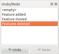
デジタル化のステップを元に戻すかやり直しします
「元に戻す」が押されるか Ctrlキー+Z (または Cmd+Z )が押された場合、すべての地物および属性の状態が、戻される操作が起こった前の状態に戻ります。通常のベクターの編集操作以外の変更(例えば、プラグインによって行われた変更)は、どのように変更が行われたかに応じて、戻ることも戻らないこともあります。
元に戻す/やり直し 履歴ウィジェットを利用する場合単純に操作の履歴リストをクリックして下さい。すべての操作は選択操作のあとであった状態に戻されます。
地物(群)の回転
Use Rotate Feature(s) to rotate one or multiple features
in the map canvas. Press the Rotate Feature(s) icon and then
click on the feature to rotate. Either click on the map to place the rotated feature or
enter an angle in the user input widget. If you want to rotate several features,
they shall be selected first.
If you enable the map tool with feature(s) selected, its (their) centroid appears and will be the rotation anchor point. If you want to move the anchor point, hold the Ctrl button and click on the map to place it.
地図上をクリックする前に Shift を保持している場合、回転が45度の段階で行われます、ユーザー入力ウィジェットの中で後で変更できます。
To abort feature rotation, you need to click on Rotate
Feature(s) icon.
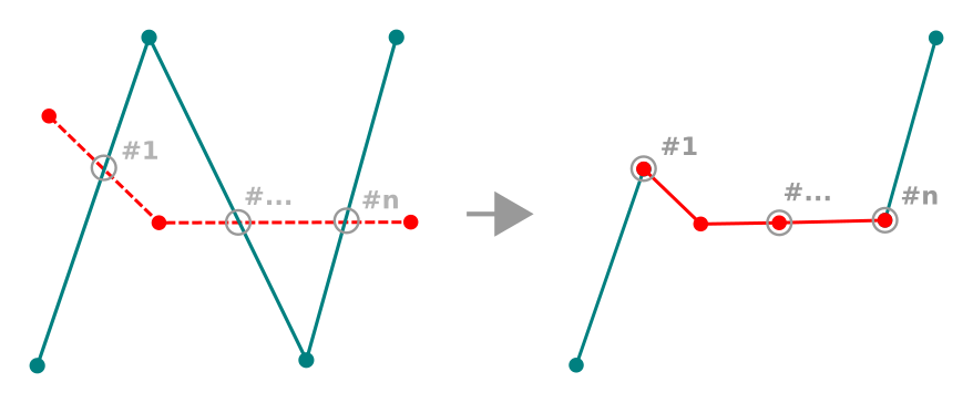
地物の簡素化
The Simplify Feature tool allows you to reduce the
number of vertices of a feature, as long as the geometry remains valid. With the
tool you can also simplify many features at once or multi-part features.
First, click on the feature or drag a rectangle over the features. A dialog where you can define a tolerance in map units, layer units or pixels pops up and a colored and simplified copy of the feature(s), using the given tolerance, appears over them. QGIS calculates the amount of vertices that can be deleted while maintaining the geometry. The higher the tolerance is the more vertices can be deleted. When the expected geometry fits your needs just click the [OK] button. The tolerance you used will be saved when leaving a project or when leaving an edit session. So you can go back to the same tolerance the next time when simplifying a feature.
To abort feature simplification, you need to click on
Simplify Feature icon.
ノート
レンダリングするためだけにジオメトリを簡素化する 設定 ‣ オプション ‣ レンダリング メニュー中の地物の簡素化オプションとは異なり、 地物を簡素化 ツールでは、永遠にデータソース内の地物のジオメトリを変更します。
パートの追加
選択された地物に 部分を追加 して、マルチポイント、マルチラインまたはマルチポリゴン地物を生成します。新しい部分は、事前に選択する必要のある既存のものの外にデジタル化する必要があります。
部分を追加 は、ジオメトリのない地物にジオメトリを追加するためにも使用できます。まず、属性テーブルで地物を選択し、 部分を追加 ツールで新しいジオメトリを数値化します。
パートの削除
部分を削除 ツールは、複数部分地物から部分を削除できます(例えば、マルチポリゴン地物からポリゴンを削除する)。ポイント、ラインとポリゴン:このツールは、すべての複数部分ジオメトリで動作します。さらに、完全な地物の幾何的構成要素を除去するために使用できます。一部を削除するには、単に対象の部分内をクリックします。
リングの追加
ツールバーの リングを追加 アイコンを使用してリングポリゴンを作成できます。これは、既存の領域の内部、外側と内側の多角形の境界の間の領域のみがリングポリゴンとして残るように、「穴」として発生する更なるポリゴンをデジタル化することが可能であることを意味します。
リングの塗りつぶし
You can use the Fill Ring function to add a ring to
a polygon and add a new feature to the layer at the same time. Using this tool,
you simply have to digitize a polygon within an existing one. Thus you need not
first use the Add Ring icon and then the
Add feature function anymore.
リングの削除
リングを削除 ツールでは、穴の内側をクリックすることで、既存のポリゴン内のリングを削除できます。このツールは、ポリゴンとマルチポリゴンの地物に対応しています。それはポリゴンの外側のリング上で使用されているとき、それは何も変わりません。
地物の変形
ツールバーの 地物を変形 ツールを使用するとラインやポリゴンの形状を変更できます。ラインの場合は、最初のラインからのライン部分を元のラインとの最後の交差まで置き換えます。
ラインを変形
ちなみに
変形ツールでラインストリングジオメトリを延長
地物を変形 を使用する、ツール既存のラインストリングジオメトリを拡張する:ラインの最初または最後の頂点にスナップして、新しいラインを描画します。検証すると、地物のジオメトリは2つのラインの組み合わせになります。
ポリゴンの場合は、ポリゴンの境界を再形成します。それが動作するためには、変形ツールの線はポリゴンの境界を少なくとも2回横切る必要があります。ラインを描画するには、地図キャンバスをクリックして頂点を追加します。終了するには、右クリックしてください。ラインと同様に、最初の交差点と最後の交差点の間のセグメントのみが考慮されます。ポリゴンの内側にあるリシェイプラインのセグメントは、ポリゴンの外側にあるものがポリゴンの外側にある部分を切り取るようになります。

ポリゴンを変形
ポリゴンでは、変形によって意図しない結果が生じることがあります。これは、ポリゴンの小さな部分を置換することが主なオーバーホールではなく、主に有効です。また、変形ラインは、無効なポリゴンを生成するので、いくつかのポリゴンリングを横切ることはできません。
ノート
変形ツールは、ポリゴンのリングまたは閉じた線の開始位置を変更することができます。だから、「二回」表されるポイントはこれ以上同じにはなりません。これは、ほとんどのアプリケーションでは問題ではないかもしれないが、考慮すべきものです。
オフセットカーブ
オフセット曲線 ツールは、ラインレイヤーの平行移動を作成します。ツールは、編集されたレイヤー(ジオメトリが変更された)に適用し、あるいはまた(それはライン/リングのコピーを作成し、編集したレイヤーに追加した場合)、背景レイヤーにできます。したがって、距離線レイヤーの作成に最適です。 ユーザー入力 ダイアログポップアップ、変位距離を示します。
ラインレイヤーのシフトを作成するには、まず編集モードに入るとアクティブにする必要があります オフセット曲線 ツール。そして、それをシフトする地物をクリックしてください。マウスを移動し、望んでいたか、ユーザー入力ウィジェットに所望の距離を入力する場所をクリックします。変更は、その後一緒に保存できます レイヤー編集を保存 ツール。
QGISのオプション]ダイアログボックス([デジタル化]タブの後 曲線ツールをオフセット セクション) 結合スタイル 、 クアドラントセグメント 、マイターリミット のようないくつかのパラメーターを設定できます。
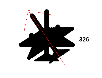
地物の分割
You can split features using the Split Features
icon on the toolbar. Just draw a line across the feature you want to split.
部分の分割
QGISでは、部分数が増加するように複数部分地物の部分を分割することが可能です。ちょうど使用して分割したい部分全体に線を引きます 部分を分割 アイコン。
ちなみに
Split a polyline feature in one-click
A single click on a snapped vertex of a line feature with the
Split Features or Split Parts tool is enough to have it
split into new features or parts.
選択地物のマージ
選択された地物をマージ ツールは、既存の地物をマージして新しい地物を作成することを可能にします。それらのジオメトリをマージして新しい地物を生成します。地物に共通の境界がない場合、マルチポリゴン/マルチライン/マルチポイント地物が作成されます。
First, select several features. Then press the Merge Selected
Features button. In the new dialog, you can select at the top of the dialog which value to
apply to each field of the new feature. That value can be:
- picked from the attributes of the initial features,
- an aggregation of the initial features attributes (Minimum, Maximum, Median, Sum, Count Concatenation... depending on the type of the field. see 統計の概要パネル for the full list of functions),
- skipped, meaning that the field will be empty,
- or manually entered, at the bottom of the rows.
選択地物の属性マージ
選択した地物の属性をマージする ツールを使用すると、地物に境界をマージせずに同じ属性を適用できます。このダイアログは、「選択された地物のマージ」ツールとは異なり、そのツールと異なり、選択されたオブジェクトは、その属性の一部は同一になりますが、ジオメトリは保持されます。
ポイントシンボルの回転
The Rotate Point Symbols allows you to change the rotation
of point symbols in the map canvas. First of all, you must apply to the symbol a
data-defined rotation: in the Layer Properties
‣ Style dialog, click the  Data-defined override widget
near the Rotation option of the highest level (preferably) of the symbol
layers and choose a field in the Field Type combobox. Values of this
field are hence used to rotate each feature’s symbol accordingly.
Data-defined override widget
near the Rotation option of the highest level (preferably) of the symbol
layers and choose a field in the Field Type combobox. Values of this
field are hence used to rotate each feature’s symbol accordingly.
ノート
As a global option, setting the rotation field at the first level of the symbol applies it to all the underlying levels while setting it at a lower level will rotate only this symbol layer (unless you have a single symbol layer).
ポイントシンボルの回転
To change the rotation of a symbol, click on a point feature in the map canvas
with the Rotate Point Symbols and move the mouse around,
holding the left button pressed. A red arrow with the rotation value
will be visualized (see Figure_rotate_point). When you release the left mouse
button again, the symbol is defined with this new rotation and the rotation
field is updated in the layer’s attribute table.
ちなみに
Ctrl キーを押し続けると回転は15度単位で実行されます。
ポイントシンボルのオフセット
ポイントシンボルをオフセット は、地図キャンバス内のポイントシンボルのレンダリングされた位置を対話的に変更することを可能にします。このツールは、 のように動作します。 ポイントシンボルを回転 ツールは、フィールドをシンボルのデータ定義の Offset(X,Y) プロパティに接続する必要がある点を除いて、オフセット座標で設定されます。地図キャンバスでシンボルを移動します。
ノート
The Offset Point Symbols tool doesn’t
move the point feature itself; you should use the Node Tool
or Move Feature tool for this purpose.
警告
Ensure to assign the same field to all symbol layers
If at least two layers of the symbol have different fields assigned to their data-defined property (e.g. rotation), the corresponding tool will consider that no field is assigned to the symbol property and won’t perform the action.
自動トレース
Usually, when using capturing map tools (add feature, add part, add ring, reshape and split), you need to click each vertex of the feature.
Using the automatic tracing mode you can speed up the digitization process.
Enable the Tracing tool by pushing the icon or pressing
t key and snap to a vertex or segment of a
feature you want to trace along. Move the mouse over another vertex or segment
you’d like to snap and instead of an usual straight line, the digitizing rubber
band represents a path from the last point you snapped to the current position.
QGIS actually uses the underlying features topology to build the shortest path
between the two points. Click and QGIS places the intermediate vertices following
the path. You no longer need to manually place all the vertices during digitization.
Tracing requires snapping to be activated in traceable layers to build the path. You should also snap to an existing vertex or segment while digitizing and ensure that the two nodes are topologically connectable following existing features, otherwise QGIS is unable to connect them and thus traces a single straight line.
ノート
最適なトレースのための地図の縮尺やスナップ設定を調整します
地図表示中にあまりにも多くの地物がある場合、トレースは、長いトレース構造の準備と大容量メモリのオーバーヘッドの可能性を回避するために、無効になります。いくつかのレイヤーをズームインまたは無効にした後、トレースは再び有効になります。
ちなみに
Quickly enable or disable automatic tracing by pressing t key
By pressing t key, tracing can be enabled/disabled anytime even while digitizing one feature, so it is possible to digitize some parts of the feature with tracing enabled and other parts with tracing disabled. Tools behave as usual when tracing is disabled.
高度なデジタル化パネル
新規または既存のジオメトリをキャプチャ、再シェーピング、分割するときには、高度なデジタル化パネルを使用できます。特定の角度に対して線を正確に平行または垂直にデジタイズするか、線を特定の角度にロックできます。さらに、新しいジオメトリを正確に定義できるように、座標を直接入力することもできます。
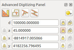
高度なデジタル化パネル
ノート
地図ビューは、地理座標系である場合のツールが有効になっていません。
The Advanced Digitizing panel can be open either with a right-click on the
toolbar and choose Advanced Digitizing panel or in View ‣
Panels ‣ Advanced Digitizing Panel. Once the panel is visible, click the
enable advanced digitizing tool button to activate the Advanced
Digitizing tool.
概念
高度なデジタル化ツールの目的は、地図キャンバスのデジタル化中にマウスを動かすときの座標、長さ、および角度をロックすることです。
相対参照または絶対参照を使用して、制約を作成することもできます。相対参照とは、次の頂点制約の値が前の頂点またはセグメントを基準とすることを意味します。
スナップ設定
 ボタンを押して、高度なデジタル化ツールのスナップ設定を設定します。ツールを共通の角度にスナップできます。オプションは次のとおりです。
共通角にスナップしない
30º度にスナップ
45º度にスナップ
90º度にスナップ
地物のスナップを制御することもできます。オプションは次のとおりです。
頂点または線分にスナップしない
プロジェクト設定に応じてスナップする
すべてのレイヤーにスナップ
キーボードショートカット
[高度なデジタイズ]パネルの使用をスピードアップするために、いくつかのキーボードショートカットがあります:
キー |
シンプル |
Ctrl + or Alt + | Shift + |
|---|---|---|---|
| d | 距離を設定 |
距離をロック |
|
| a | 角度を設定 |
角度をロック |
最後のセグメントに対する相対的な角度に切り替え |
| x | Set x coordinate | Lock x coordinate | Toggle relative x to last vertex |
| y | Set y coordinate | Lock y coordinate | Toggle relative y to last vertex |
| c | 作図モードを切り替え |
||
| p | 垂直と水平モードを切り替え |
||
絶対参照デジタイジング
新しいジオメトリを最初から描画するときは、与えられた座標で頂点をデジタル化することが可能です。
たとえば、ポリゴンレイヤーに新しい地物を追加するには、 ボタンをクリックします。地物の編集を開始するX座標とY座標を選択してから、次の操作を実行できます。
- Click the x text box (or use the x keyboard shortcuts).
必要なX座標値を入力し、 Enter を押すか、
 ボタンを右に移動して、地図キャンバス上でマウスをX軸にロックします。
- Click the y text box (or use the y keyboard shortcuts).
必要なY座標値を入力し、 Enter を押すか、
ボタンを右に移動して、地図キャンバス上でマウスをY軸にロックします。
2つの青い点線と緑の十字は、入力した正確な座標を示します。地図キャンバスをクリックしてデジタイズを開始します。マウスの位置は緑の十字でロックされます。
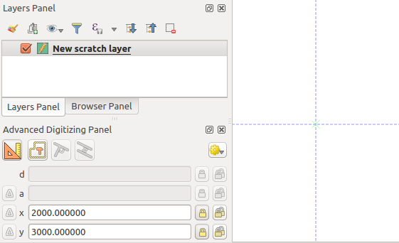
与えられた座標で描画を開始
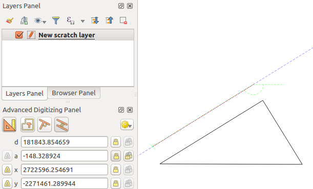
フリーハンドでデジタル化を続行したり、新しい座標ペアを追加したり、セグメントの 長さ (距離)と 角度 を入力できます。
If you want to draw a segment of a given length, click the d
(distance) text box (keyboard shortcut d), type the distance value (in
map units) and press Enter or click the button on the right to
lock the mouse in the map canvas to the length of the segment.
In the map canvas, the clicked point is surrounded by a circle whose radius is
the value entered in the distance text box.
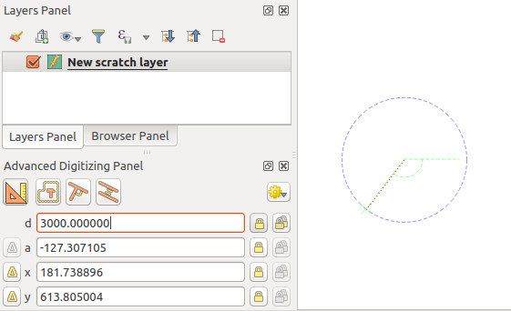
固定長セグメント
Finally, you can also choose the angle of the segment. As described before ,
click the a (angle) text box (keyboard shortcut a), type the
angle value (in degrees), and press Enter or click the buttons
on the right to lock it. In this way the segment will follow the desired angle:
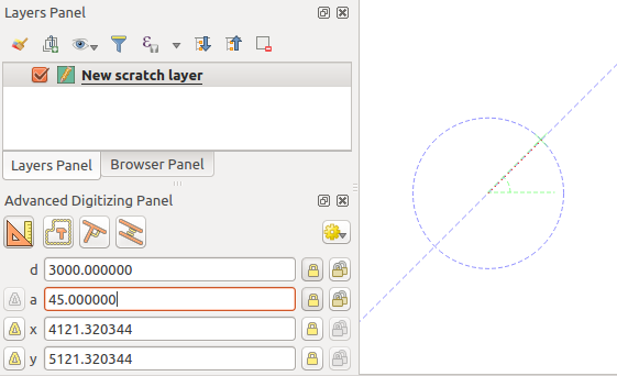
固定角セグメント
相対参照デジタイジング
角度または座標の絶対値を使用する代わりに、最後のデジタル化された頂点またはセグメントを基準にした値を使用することもできます。
For angles, you can click the  button on the left of the a
text box (or press Shift + a) to toggle relative angles to the previous
segment. With that option on, angles are measured between the last segment
and the mouse pointer.
button on the left of the a
text box (or press Shift + a) to toggle relative angles to the previous
segment. With that option on, angles are measured between the last segment
and the mouse pointer.
For coordinates, click the buttons to the left of the x or
y text boxes (or press Shift + x or Shift + y) to
toggle relative coordinates to the previous vertex. With these options on,
coordinates measurement will consider the last vertex to be the x and y axes
origin.
連続的ロック
Both in absolute or relative reference digitizing, angle, distance, x and y
constraints can be locked continuously by clicking the  Continuous lock buttons. Using continuous lock allows you to
digitize several points or vertexes using the same constraints.
Continuous lock buttons. Using continuous lock allows you to
digitize several points or vertexes using the same constraints.
Parallel and perpendiculars line
上記のすべてのツールは、  垂直 および
  平行 ツールと組み合わせできます。これらの2つのツールでは、描画セグメントを別のセグメントと完全に垂直または平行にできます。
To draw a perpendicular segment, during the editing click the
Perpendicular icon (keyboard shortcut p) to
activate it. Before drawing the perpendicular line,
click on the segment of an existing feature that you want to be perpendicular
to (the line of the existing feature will be colored in light orange); you
should see a blue dotted line where your feature will be snapped:
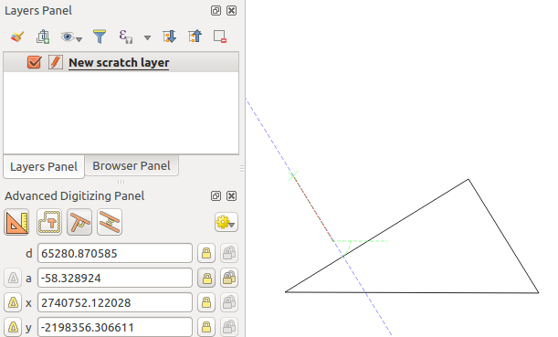
垂直デジタイズ
To draw a parallel feature, the steps are the same: click on the
Parallel icon (keyboard shortcut p twice), click on
the segment you want to use as reference and start drawing your feature:
平行デジタイジング
これらの2つのツールは、直角と平行な角度の直角を見つけて、編集中にこのパラメーターをロックします。
作図モード
You can enable and disable construction mode by clicking on the
 Construction icon or with the c keyboard
shortcut. While in construction mode, clicking the map canvas won’t add new
vertexes, but will capture the clicks’ positions so that you can use them as
reference points to then lock distance, angle or x and y relative values.
Construction icon or with the c keyboard
shortcut. While in construction mode, clicking the map canvas won’t add new
vertexes, but will capture the clicks’ positions so that you can use them as
reference points to then lock distance, angle or x and y relative values.
一例として、構築モードを使用して、ある点を既存の点から正確な距離に描画できます。
With an existing point in the map canvas and the snapping mode correctly
activated, you can easily draw other points at given distances and angles from
it. In addition to the button, you have to activate also the
construction mode by clicking the Construction
icon or with the c keyboard shortcut.
Click next to the point from which you want to calculate the distance and click on the d box (d shortcut) type the desired distance and press Enter to lock the mouse position in the map canvas:
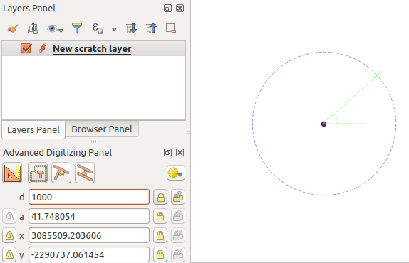
点からの距離
Before adding the new point, press c to exit the construction mode. Now, you can click on the map canvas, and the point will be placed at the distance entered.
You can also use the angle constraint to, for example, create another point at
the same distance of the original one, but at a particular angle from the newly
added point. Click the Construction icon or with the
c keyboard shortcut to enter construction mode. Click the recently added
point, and then the other one to set a direction segment. Then, click on the
d text box (d shortcut) type the desired distance and press
Enter. Click the a text box (a shortcut) type the
angle you want and press Enter. The mouse position will be locked both in
distance and angle.

点からの距離と角度
Before adding the new point, press c to exit the construction mode. Now, you can click on the map canvas, and the point will be placed at the distance and angle entered. Repeating the process, several points can be added.
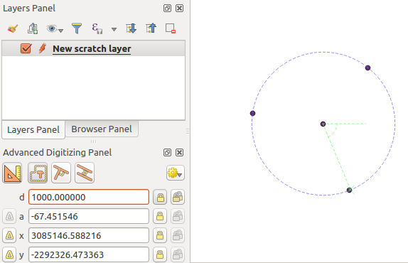
所与の距離と角度の点