` `
Creare Layer
Layers can be created in many ways, including:
- empty layers from scratch;
- layers from existing layers;
- layers from the clipboard;
- layers as a result of an SQL-like query based on one or many layers: the virtual layer.
QGIS also provides tools to import/export different formats.
Creating new vector layers
QGIS allows you to create new Shapefile layers, new SpatiaLite layers, new GPX layers and new Temporary Scratch layers. Creation of a new GRASS layer is supported within the GRASS plugin. (Please refer to section Creare un nuovo layer vettoriale GRASS for more information on creating GRASS vector layers.)
Creare un nuovo layer Shapefile
To create a new Shapefile layer, choose Create
Layer ‣  New Shapefile Layer... from the
Layer menu. The New Shapefile Layer dialog will be
displayed as shown in figure_create_shapefile. Choose the type of layer
(point, line or polygon) and the CRS (coordinate reference system).
New Shapefile Layer... from the
Layer menu. The New Shapefile Layer dialog will be
displayed as shown in figure_create_shapefile. Choose the type of layer
(point, line or polygon) and the CRS (coordinate reference system).
Note that QGIS does not yet support creation of 2.5D features (i.e., features with X,Y,Z coordinates).
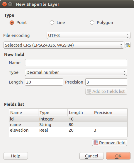
Finestra di dialogo creazione nuovo Layer Shapefile
To complete the creation of the new Shapefile layer, add the desired attributes
by specifying a name and type for each attribute and clicking on the
[Add to fields list] button.
A first ‘id’ column is added by default but can be
removed, if not wanted. Only Decimal number  ,
Whole number , Text data
and Date attributes are
supported. Additionally, depending on the attribute type, you can also define
the length and precision of the new attribute column. Once you are happy with the
attributes, click [OK] and provide a name for the Shapefile. QGIS will
automatically add the .shp extension to the name you specify. Once the
Shapefile has been created, it will be added to the map as a new layer, and you can
edit it in the same way as described in section Modifica di un layer esistente.
,
Whole number , Text data
and Date attributes are
supported. Additionally, depending on the attribute type, you can also define
the length and precision of the new attribute column. Once you are happy with the
attributes, click [OK] and provide a name for the Shapefile. QGIS will
automatically add the .shp extension to the name you specify. Once the
Shapefile has been created, it will be added to the map as a new layer, and you can
edit it in the same way as described in section Modifica di un layer esistente.
Creare un nuovo layer SpatiaLite
To create a new SpatiaLite layer for editing, choose New ‣
 New SpatiaLite Layer... from the
Layer menu. The New SpatiaLite Layer dialog will
be displayed as shown in Figure_create_spatialite.
New SpatiaLite Layer... from the
Layer menu. The New SpatiaLite Layer dialog will
be displayed as shown in Figure_create_spatialite.
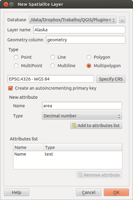
Finestra di dialogo creazione Nuovo layer SpatiaLite
The first step is to select an existing SpatiaLite database or to create a new
SpatiaLite database. This can be done with the browse button  to
the right of the database field. Then, add a name for the new layer, define
the layer type, and specify the coordinate reference system with [Specify CRS].
If desired, you can select
to
the right of the database field. Then, add a name for the new layer, define
the layer type, and specify the coordinate reference system with [Specify CRS].
If desired, you can select  Create an autoincrementing primary key.
To define an attribute table for the new SpatiaLite layer, add the names of the attribute columns you want to create with the corresponding column type, and click on the [Add to attribute list] button. Once you are happy with the attributes, click [OK]. QGIS will automatically add the new layer to the legend, and you can edit it in the same way as described in section Modifica di un layer esistente.
Ulteriore gestione dei layers di SpatiaLite può essere eseguita con il DB Manager. Vedi Plugin DB Manager.
Creating a new GeoPackage layer
To create a new GeoPackage layer go to Layer ‣ New ‣
 New GeoPackage Layer....
The New GeoPackage Layer dialog will
be displayed as shown in figure_create_geopackage.
New GeoPackage Layer....
The New GeoPackage Layer dialog will
be displayed as shown in figure_create_geopackage.
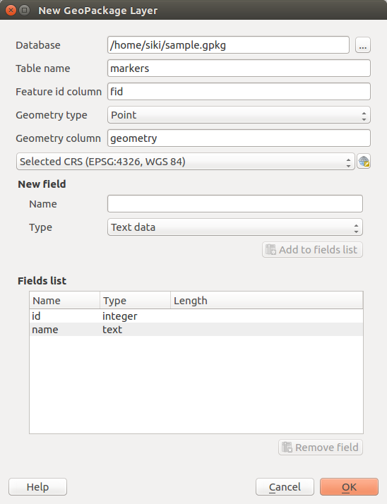
Creating a New GeoPackage layer dialog
The first step is to select an existing GeoPackage or create a new one. This can be done by pressing the ellipses [...] button at the right of the Database field. Then, give a name for the new layer, define the layer type and specify the coordinate reference system with [Specify CRS].
To define an attribute table for the new GeoPackage layer, add the names of the attribute columns you want to create with the corresponding column type, and click on the [Add to fields list] button. Once you are happy with the attributes, click [OK]. QGIS will automatically add the new layer to the legend, and you can edit it in the same way as described in section Modifica di un layer esistente.
Creare un nuovo layer GPX
Per creare un nuovo file GPX, devi prima aver caricato il plugin GPS. Plugins ‣  Plugin Manager... apre la finestra di dialogo Plugin Manager. Attiva la casella GPS Tools.
When this plugin is loaded, choose New ‣  Create new GPX Layer... from the Layer menu.
In the Save new GPX file as dialog, choose where to save the
new file and press [Save]. Three new layers are added to the
Layers Panel: waypoints, routes and tracks with
predefined structure.
Create new GPX Layer... from the Layer menu.
In the Save new GPX file as dialog, choose where to save the
new file and press [Save]. Three new layers are added to the
Layers Panel: waypoints, routes and tracks with
predefined structure.
Creare un nuovo vettore temporaneo
Temporary Scratch Layers are in-memory layers, meaning that they are not saved on disk and will be discarded when QGIS is closed. They can be handy to store features you temporarily need or as intermediate layers during geoprocessing operations.
Empty, editable temporary scratch layers can be defined using Layer ‣
Create Layer ‣ New Temporary Scratch Layer. Here you can create
 Multipoint, Multiline
and Multipolygon Layers beneath
Multipoint, Multiline
and Multipolygon Layers beneath
 Point, Line and
Polygon layers.
Point, Line and
Polygon layers.
You can also create Temporary Scratch Layers from the clipboard. See Creating new layers from the clipboard.
Creating new layers from an existing layer
Both raster and vector layers can be saved in a different format and/or reprojected to a different coordinate reference system (CRS) using the Save As... function in the layer context menu (by right-clicking in the layer in the layer tree) or in the Layer ‣ Save As... menu.
Parametri comuni
The Save As dialog shows several parameters to change the behavior when saving the layer. Common parameters for raster and vector are:
- Format
Nome del File
- CRS can be changed to reproject the data
- Add saved file to map to add the new layer to the canvas
Estensione (i valori possibili sono Estensione del Layer, Estensione della mappa o Estensione definita dall’utente)
Tuttavia, alcuni parametri sono specifici per i formati raster e vettoriali
Parametri specifici per i Raster
Modalità uscita (può essere Dati grezzi o Immagine visualizzata)
Risoluzione
- Create Options: advanced options (file compression, block sizes, colorimetry...) to fine tune the output file. See the gdal-ogr driver documentation.
Pyramidi creazione
- VRT Tiles
Valori nulli
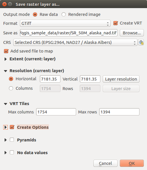
Salvare come un nuovo layer raster
Parametri specifici per i Vettori
A seconda del formato di esportazione, alcune di queste opzioni sono disponibili o meno:
Codifica
Salva solo le geometrie selezionate
Seleziona i campi da esportare e le loro opzioni di esportazione. Nel caso in cui imposti i comportamenti dei campi con alcuni Edit widgets ad esempio “valore”, puoi mantenere i valori visualizzati nel layer scegliendo
Sostituisci tutti i valori grezzi selezionati dai valori mostrati.Esporta simbologia: opzione che puoi utilizzare principalmente per l’esportazione del formato DXF e per tutti i formati di file che gestiscono le tipologie di file OGR (vedi nota di seguito) come i formati DXF, KML, i formati tabelle:
Nessuna simbologia: stile di default dell’applicazione che legge i dati
Simbologia geometrie: salva lo stile utilizzando gli stili OGR (vedi la nota di seguito)
Simbologia simboli vettore: salva con gli stili OGR (vedi nota di seguito) ma esporta la stessa geometria più volte se sono utilizzati più simboli
Un valore di Scala può essere applicato alle scelte più recenti.
Nota
OGR Feature Styles are a way to store style directly in the data as a hidden attribute. Only some formats can handle this kind of information. KML, DXF and TAB file formats are such formats. For advanced users, you can read the OGR Feature Styles specification document.
Geometria: puoi definire le caratteristiche geometriche del layer in output
- geometry type: keep the original geometry of the features when set to Automatic, otherwise removes or overrides it with any type. You can add an empty geometry column to an attribute table, remove the geometry column of a spatial layer.
- Force multi-type: force creation of multi-geometry features in the layer
Include z-dimension alle geometrie.
Suggerimento
Overriding layer geometry type makes it possible to do things like save a
geometryless table (e.g. .csv file) into a shapefile WITH any type of
geometry (point, line, polygon), so that geometries can then be manually added
to rows with the  Add Part tool .
- Datasources Options, Layer Options or Custom Options which allow you to configure some advanced parameters. See the gdal-ogr driver documentation.
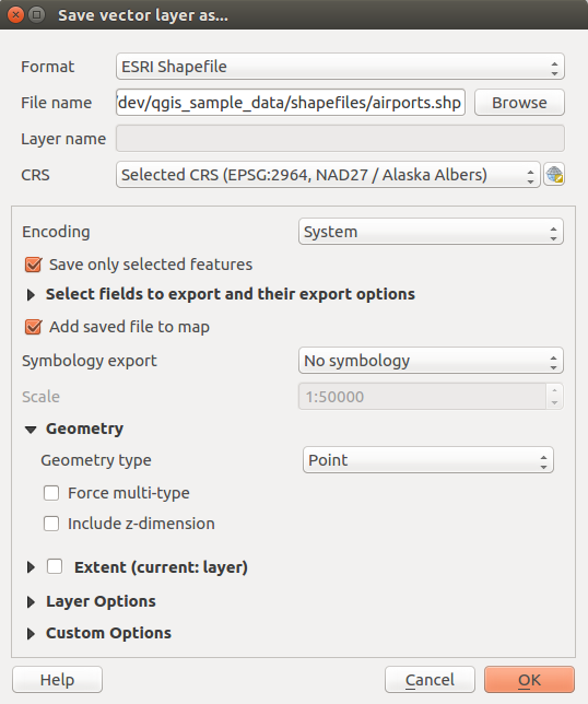
Salvare come un nuovo layer vettoriale
Quando si salva un layer vettoriale in un file esistente, a seconda delle capacità del formato di output (Geopackage, SpatiaLite, FileGDB ...), l’utente può decidere se:
sovrascrivere l’intero file
sovrascrivere solo il layer di destinazione (il nome del layer è configurabile)
aggiungere geometrie ad un layer esistente
aggiungere geometrie, aggiungere nuovi campi se ce ne sono.
Sono disponibili opzioni per aggiungere geometrie ai formati come ESRI Shapefile, MapInfo .tab,.
Creating new DXF files
Besides the Save As... dialog which provides options to export a single layer to another format, including *.DXF, QGIS provides another tool to export multiple layers as a single DXF layers. It’s accessible in the Project ‣ DXF Export... menu.
The DXF Export dialog allows the user to:
indicate the destination layer file;
choose the symbology mode and scale (see the OGR Feature Styles note);
select the encoding and CRS;
check the loaded layers to include in the DXF files or pick them from an existing visibility preset.
For each layer, you can choose a field whose values are used to split features in generated destination layers in the DXF output. You can also choose to
Use the layer title as name if set and keep features
grouped.choose to only Export features intersecting the current map extent.
Creating new layers from the clipboard
Le geometrie che si trovano negli appunti possono essere incollate in un nuovo layer. Seleziona alcune geometrie e poi copiale in un nuovo layer usando Modifica ‣ Incolla geometrie come ‣ e scegliendo:
- New Vector Layer...: you need to select the layer CRS, poping up the Save vector layer as... dialog from which you can select any supported data format (see Creating new layers from an existing layer for parameters);
- or Temporary Scratch Layer...: you need to select the layer CRS and give a name.
Viene creato un nuovo layer, completo delle geometrie selezionate e relativi attributi e aggiunto alla visualizzazione mappa se richiesto.
Nota
Creating layers from clipboard applies to features selected and copied within QGIS and also to features from another source defined using well-known text (WKT).
Creating virtual layers
Virtual layers are a special kind of vector layer. They allow you to define a layer as the result of an SQL query involving any number of other vector layers that QGIS is able to open. Virtual layers do not carry data by themselves and can be seen as views to other layers.
To create a virtual layer, open the virtual layer creation dialog by clicking on Add Virtual Layer in the Layer menu or from the corresponding toolbar.
The dialog allows you to specify a Layer name and an SQL Query. The query can use the name (or id) of loaded vector layers as tables, as well as their field names as columns.
Ad esempio, se hai un layer chiamato airports, puoi creare un nuovo layer virtuale da denominare public_airports con una query SQL del tipo:
SELECT *
FROM airports
WHERE USE = "Civilian/Public"
The SQL query will be executed, regardless of the underlying provider of the airports layer, even if this provider does not directly support SQL queries.
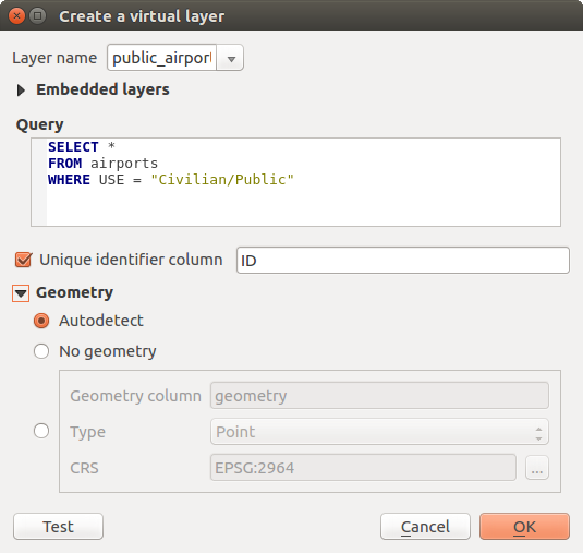
Finestra di dialogo creare layer virtuali
Joins and complex queries can also be created, for example, to join airports and country information:
SELECT airports.*, country.population
FROM airports
JOIN country
ON airports.country = country.name
Nota
Layers virtuali possono essere creati anche usando la finestra di dialogo SQL di Plugin DB Manager.
Embedding layers for use in queries
Oltre ai layers vettoriali disponibili nell’area di visualizzazione della mappa, l’ utente può aggiungere layers alla lista Layers inckusi, layers che può utilizzare nelle query senza doverli mostrare nell’area di visualizzazione della mappa o nel Layers Panel.
Per incorporare un layer, fariclick su Aggiungi e inserisci Nome locale, Sorgente dati, Codifica e il percorso della Sorgente dati.
Il pulsante Importa consente di aggiungere i layer caricati nell’area di disegno della mappa all’elenco dei layer incorporati. Questo consente di rimuovere successivamente questi layers dal Layers Panel senza interrompere alcuna query esistente.
Supported query language
Il motore sottostante utilizza SQLite e SpatiaLite per funzionare.
Ciò significa che è possibile utilizzare tutti l’SQL che l’installazione locale di SQLite comprende.
Funzioni di SQLite e funzioni spaziali di SpatiaLite possono anche essere utilizzate in una query di layer virtuale. Ad esempio, la creazione di un layer di punti da un layer di solo attributo può essere fatto con una query simile a:
SELECT id, MakePoint(x, y, 4326) as geometry
FROM coordinates
Functions of QGIS expressions possono essere utilizzate anche in una query di layer virtuale..
Per fare riferimento alla colonna geometrica di un layer, utilizzare il nome geometria.
Contrariamente a una query SQL pura, devono essere denominati tutti i campi di una query di layer virtuale. Non dimenticare di utilizzare la parola chiave as per indicare le colonne se sono il risultato di un calcolo o di una funzione.
Problemi relativi alle prestazioni
Con parametri predefiniti, il motore del layer virtuale proverà a rilevare il tipo delle diverse colonne della query, incluso il tipo di colonna geometria se presente.
Questo viene fatto analizzando l’interrogazione se possibile o recuperando la prima riga dell’interrogazione (LIMIT 1) in ultima istanza. Il recupero della prima riga del risultato per creare lo strato può essere indesiderabile per motivi di prestazioni
La finestra di dialogo per creare un layer virtuale ti permette di specificare diversi parametri.
Colonna identificativa univoca: questa opzione ti permette di specificare quale campo dell’interrogazione rappresenta i valori interi univoci che QGIS può utilizzare come identificatore di riga. Per default, viene utilizzato un valore intero autoincrementale. Specificando una colonna identificatore univoco potrai velocizzare la selezione delle righe.
Nessuna geometria: questa opzione forza il layer virtuale a ignorare qualsiasi campo geometria. Il layer risultante sarà solamente un layer tabella attributi.
Colonna geometria: questa opzione ti permette di specificare il nome della colonna da utilizzare come geometria del layer.
Tipo: questa opzione ti permette di specificare il tipo di geometria del layer virtuale.
SR: quest’opzione ti permette di specificare il sistema di riferimento delle coordinate del layer virtuale.
Commenti speciali
L’interprete del layer virtuale tenta di determinare il tipo di ogni colonna della query. Se non riesce, viene eseguita la prima riga della query per determinare i tipi colonna.
Il tipo di una particolare colonna può essere specificato direttamente nella query utilizzando alcuni commenti speciali.
La sintassi è la seguente: /*: type*/. Deve essere inserita subito dopo il nome di una colonna. il tipo può essere int per interi, real per numeri a virgola mobile o text.
Ad esempio:
SELECT id+1 as nid /*:int*/
FROM table
Il tipo e il sistema di riferimento della colonna geometrica può essere impostato anche grazie a speciali commenti con la seguente sintassi /*:gtype: srid*/ dove gtype è il tipo geometrico (point, linestring, polygon, multipoint, multilinestring or multipolygon) e srid un intero che rappresenta il codice EPSG di un sistema di riferimento di coordinate.
Uso degli indici
Quando si interagisce con un layer virtuale, gli indici di questo layer vengono utilizzati nei seguenti modi:
se viene usato = nella colonna chiave primaria del layer, al fornitore di dati sottostante verrà richiesto un id particolare (FilterFid)
per tutti gli altri predicati (>, <=, !=, etc.) o per richiesta su una colonna senza chiave primaria, verrà utilizzata una richiesta costruita da un’ espressione per il driver attivo. Ciò significa che gli indici possono essere utilizzati sui drivers di database, se esistono.
Esiste una sintassi specifica per gestire le predicazioni spaziali nelle richieste e innesca l’utilizzo di un indice spaziale: una colonna nascosta denominata _search_frame_ esiste per ogni layer virtuale. Questa colonna può essere paragonata per l’uguaglianza con un riquadro di limitazione. Ad esempio:
SELECT *
FROM vtab
WHERE _search_frame_=BuildMbr(-2.10,49.38,-1.3,49.99,4326)
I predicati binari spaziali come ST_Intersects consentono significative accelerazioni quando utilizzati in combinazione con questa sintassi dell’indice spaziale.