` `
Outils généraux
- Aide contextuelle
- Panneaux
- Rendu
- Sauvegarder et Partager les propriétés d’une couche
- sélecteur de couleur
- Modes de fusion
- Zoomer et se déplacer
- Mesurer
- Sélectionner des entités
- Valeurs définies par des données
- Identify Features
- Outils d’annotation
- Signets spatiaux
- Inclusion de projets
- Décorations
- Authentification
- Variables
Aide contextuelle
When you need help on a specific topic, you can access context help via the [Help] button available in most dialogs — please note that third-party plugins can point to dedicated web pages.
Panneaux
QGIS provides by default many panels to work with. Some of these panels are described below while others may be found in different parts of the document. A complete list of default panels provided by QGIS is available at Panneaux.
Le panneau Couches
The layers Panel lists all the layers in the project and helps you manage their visibility. A layer can be selected and dragged up or down in the legend to change the Z-ordering. Z-ordering means that layers listed nearer the top of the legend are drawn over layers listed lower down in the legend.
Note
Le comportement de l’empilement de couches peut être supplanté par le panneau Ordre des couches.
En haut du panneau de couches, une barre d’outils vous permet de :
 Open the layer styling dock: toggle the layer styling
panel on and off.
 Manage Visibility: control visibility of layers and
preset layers combination.
 Filtrer le contenu de légende par le contenu de la carte: seules les couches qui sont visibles et dont les entités intersectent le canevas de carte actuel ont leur style affiché dans le panneau des couches. Dans les autres cas, un symbole générique NULL est appliqué à la couche. En se basant sur la symbologie de la couche, c’est un moyen pratique pour identifier quel type d’entité de quelles couches sont situées dans votre secteur d’intérêt.
 Filter Legend by Expression: helps you apply an
expression to remove from the selected layer tree styles that have no feature
satisfying the condition. This can be used for example to highlight features
that are within a given area/feature of another layer.
From the drop-down list, you can edit and clear the expression set.
 Étendre tout ou
  Réduire tout, les couches et les groupes du panneau des couches.
- and
 Remove Layer/Group currently selected.

Barre d’outils de couches dans le panneau couches
Note
Tools to manage the layers panel are also available to layout the map and legend items of the print composer
Preset the layers visibility
The button  allows you to add Presets views in the legend.
Presets are a way to save and easily restore a combination of layers with their
current style. To add a preset view, just set visible the layers you want, with
their desired symbology, and click on
  button.
Choose Add Preset... from the drop-down menu and give a name to the preset.
The added preset is listed at the bottom of the drop-down menu and is recalled by
clicking on it.
The Replace Preset ‣ option helps you overwrite a preset content with the current map view while the Remove Current Preset button deletes the active preset.
All the added presets are also present in the map composer in order to allow you to create a map layout based on your specific views (see Propriétés principales).
Interact with Groups and layers
Les couches peuvent être organisées en groupe. Il y a deux manières de procéder :
Appuyez sur l’icône
 pour ajouter un nouveau groupe. Renseignez un nom pour le groupe et appuyez sur Entrée. Cliquez maintenant sur une couche existante et déplacez-là à l’intérieur du groupe.
- Select some layers, right click in the legend window and choose Group Selected. The selected layers will automatically be placed in a new group.
To bring a layer out of a group, you can drag it out, or right click on it and choose Move to top-level; the layer is placed at the same level than the group it was inside. Groups can also be nested inside other groups.
La case à cocher d’un groupe permet d’afficher ou de cacher toutes les couches du groupe en un seul clic.
Enabling the Mutually Exclusive Group option you can make a group have only one layer visible at the same time. Whenever a layer within the group is set visible the others will be toggled not visible.
It is possible to select more than one layer or group at the same time by holding down the Ctrl key while selecting the layers with the left mouse button. You can then move all selected layers to a new group at the same time.
You may also delete more than one layer or group at once by selecting several items with the Ctrl key and pressing Ctrl+D afterwards. This way, all selected layers or groups will be removed from the layers list.
Éditer le style des couches vecteurs
From the Layers panel, you have shortcuts to easily and quickly edit the layer rendering. Right-click on a vector layer and select Styles ‣ in the list in order to:
- see the currently applied styles to the layer. In case you defined many styles for the layer, you can switch from one to another and have your layer rendering automatically updated in the map canvas.
copier le style courant et, lorsque c’est possible, coller un style copié depuis une autre couche.
- rename the current style, add a new one (which is actually a copy of the current one) or delete the current style (when multiple styles available).
Note
The previous options are also available for raster layer.
Whether the features in the vector layer have all the same unique symbol or they are classified (in that case, the layer is displayed in a tree structure with each class as sub-item), the following options are available at layer level or class level:
- a Edit Symbol... button to open the The Symbol Selector dialog and update any property (symbol, size, color...) of the layer or feature symbol. Double-clicking on a feature does also open the Symbol Selector dialog.
- a sélecteur de couleur widget with a Color Wheel from which you can click a color and have it automatically update the symbol fill color. For convenience, Recent colors are available at the bottom of the color wheel.
- a
 Show All Items and
  Hide All
Items to toggle on or off the visibility of all the classes of features. This avoids
(un)checking items one by one.
Astuce
Partager rapidement un style de couche
From the context menu, copy the style of a layer and paste it to a group or a selection of layers: the style is applied to all the layers that are of the same type (vector vs raster) as the original layer and, in case of vector, have the same geometry type (point, line or polygon).
Working with the Legend independent layer order
There is a panel that allows you to define an independent drawing order for
the layers panel. You can activate it in the menu Settings
‣ Panels ‣ Layer Order Panel. This feature allows you to, for instance,
order your layers in order of importance, but still display them in the
correct order (see figure_layer_order; you can notice that the airports
features are displayed over the alaska polygon despite their layers
placement in the Layers panel).
Unchecking the  Control rendering order box underneath
the list of layers will cause a revert to default behavior.
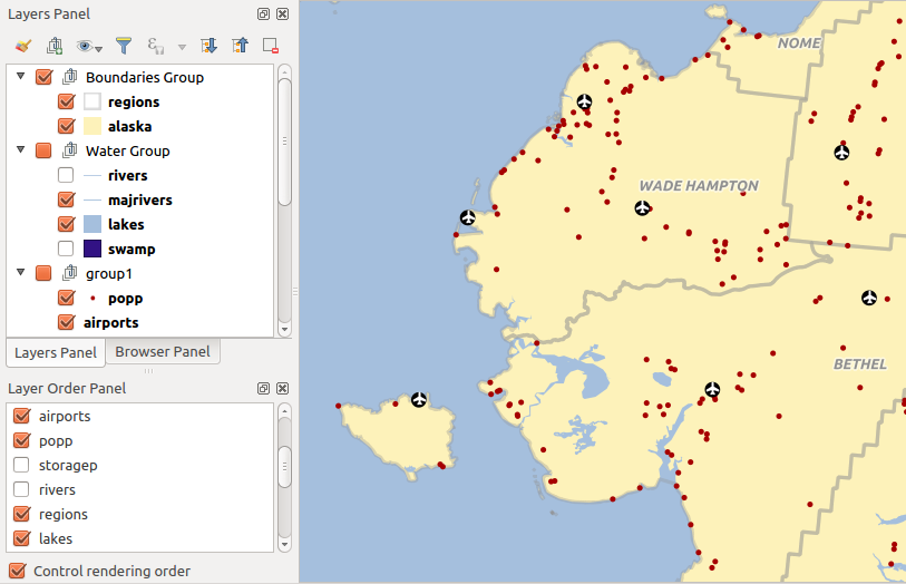
Define a legend independent layer order
Panneau de style de couche
This panel is somehow a shortcut to some of the features of the layer properties dialog. It indeed offers you a quick and handy way to define the rendering and the behavior of a layer, and to visualize its effects without opening the layer properties dialog.
Besides avoiding you dealing with the modal and blocking dialog of the layer properties, it also avoids you cluttering the screen with features dialogs given that it embeds most of them (color selector, effects properties, rule edit, label substitution...): e.g., clicking color buttons inside the layer style panel causes the color selector dialog to be opened inside the layer style panel itself rather than as a separate dialog.
From a drop-down list of current layers in the layer panel, select an item and:
- set its symbology, transparency, and histogram in case of raster layer. These options are the same available in Fenêtre Propriétés de la couche raster
- set its symbology, and labels. These options are the same available in Fenêtre Propriétés d’une couche vecteur
- manage the associated style(s) as described in Gestion des styles personnalisés
- follow the whole history of changes you applied to the layer style in the current project; you can therefore cancel or restore to any state by selecting it in the list and hit [Apply] button.
Another powerful feature of this panel is the Live update checkbox. Tick it and your changes are automatically rendered in the map canvas as you go on. You no longer need to hit the [Apply] button.
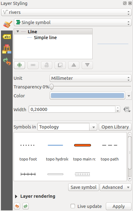
Defining a layer symbology from the layer styling panel
Astuce
Add custom tabs to the Layer Styling panel
Using PyQGIS, you can set new tabs to manage layer properties in the Layer Styling Panel. See https://nathanw.net/2016/06/29/qgis-style-dock-part-2-plugin-panels/ for an example.
Panneau de résumé statistiques
This panel can show some statistics on a specific vector layers. The panel allows users to choose:
- the vector layer;
- the column or the expression;
- filter statistics to selected features;
- refresh the informations;
- the statistics information to display with the bottom right button.
Statistic information available are (depending on the field’s type):
Tableau : statistique disponible pour chaque champ
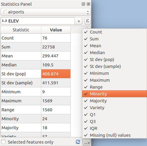
Montrer les statistiques dans le champs
QGIS Overview Panel
In QGIS, you can use an overview panel that provides a full extent view of layers added to it. Within the view is a rectangle showing the current map extent. This allows you to quickly determine which area of the map you are currently viewing. Note that labels are not rendered to the map overview even if the layers in the map overview have been set up for labelling. If you click and drag the red rectangle in the overview that shows your current extent, the main map view will update accordingly.
Gestion des logs
When loading or processing some operations, you can track and follow messages
that appear in different tabs using the  Log Messages Panel.
It can be activated using the most right icon in the bottom status bar.
Panneau Annuler/Refaire
For each layer being edited, this panel shows the list of actions done, allowing to quickly undo a set of actions by simply selecting the action listed above. More details at Undo and Redo edits.
Rendu
Par défaut, QGIS effectue le rendu de toutes les couches visibles à chaque fois que l’affichage de la carte est mis à jour. Les évènements qui déclenchent ce rafraîchissement incluent :
- Adding a layer
- Panning or zooming
- Resizing the QGIS window
- Changing the visibility of a layer or layers
QGIS vous laisse contrôler le processus de rendu de plusieurs manières.
Rendu dépendant de l’échelle
Scale-dependent rendering allows you to specify the minimum and maximum scales
at which a layer (raster or vector) will be visible. To set scale-dependent rendering,
open the Properties dialog by double-clicking on the layer in the legend.
On the General tab, tick the  Scale
dependent visibility checkbox and enter the Minimum (exclusive) and
Maximum (inclusive) scale values.
You can also activate the scale dependent visibility on a layer from the Layers panel. Right-click on the layer and in the context menu, select Set Layer Scale Visibility.
The  Set to current canvas scale button helps you use
the current map canvas scale as boundary of the range visibility.
Note
When a layer is not rendered in the map canvas due to the map scale out of its visibility scale range, the layer is greyed in the Layers panel and a new option Zoom to Visible Scale appears in the layer context menu. Select it and the map is zoomed to the layer’s nearest visibility scale.
Contrôler le rendu
Le rendu de la carte peut être contrôlé de différentes manières, décrites ci-dessous.
Suspendre le rendu
To suspend rendering, click the  Render checkbox in the
lower right corner of the status bar. When the
  Render
checkbox is not checked, QGIS does not redraw the canvas in response to any of
the events described in section Rendu. Examples of when you
might want to suspend rendering include:
- Adding many layers and symbolizing them prior to drawing
- Adding one or more large layers and setting scale dependency before drawing
- Adding one or more large layers and zooming to a specific view before drawing
- Any combination of the above
Cocher la case  Rendu activera de nouveau le rendu et provoquera un rafraîchissement immédiat de la carte.
Définir les options d’ajout de couche
You can set an option to always load new layers without drawing them. This
means the layer will be added to the map, but its visibility checkbox in the
legend will be unchecked by default. To set this option, choose menu option
Settings ‣ Options and click on the Rendering
tab. Uncheck the  By default new layers added to the map
should be displayed checkbox. Any layer subsequently added to the map will be off
(invisible) by default.
Arrêter le rendu
To stop the map drawing, press the ESC key. This will halt the refresh of the map canvas and leave the map partially drawn. It may take a bit of time between pressing ESC and the time the map drawing is halted.
Note
Il n’est maintenant plus possible d’arrêter le rendu — cela a été désactivé dans Qt4 à cause de problèmes et de crashes dans l’interface utilisateur (IHM).
Influencer la qualité du rendu
QGIS dispose d’une option qui permet d’influencer la qualité du rendu de la carte. Dans le menu Préférences ‣ Options puis l’onglet Rendu, sélectionnez ou désélectionnez la case  Les lignes semblent moins déchiquetées aux dépends d’une certaine vitesse d’exécution.
Accéler le rendu
Il y a plusieurs manières d’améliorer la rapidité du rendu de la carte. Dans le menu Préférences ‣ Options puis onglet Rendu, sélectionnez ou désélectionnez les cases suivantes :
 Use render caching where possible to speed up redraws
 Rendu des couches en parallèle en utilisant plusieurs cœurs du processeur puis définissez le
  Nombre de cœurs à utiliser.
Le rendu cartographique est calculé en arrière-plan sur une image distincte et chaque
 Intervalle de rafraîchissement de l’affichage de la carte, le contenu (hors écran) est pris pour mettre à jour la représentation visible. Si le rendu se termine plus rapidement que cette durée, il sera affiché instantanément.
- With
 Enable Feature simplification by default for newly
added layers, you simplify features’ geometry (less nodes) and as a result,
they quickly display.
Be aware that you can also face rendering inconsistencies.
sélecteur de couleur
The select color dialog will appear whenever you push
the  icon to choose a color. The features of this dialog
depends on the state of the Use native color chooser dialogs parameter
checkbox in Settings ‣ Options ‣ General menu.
When checked, the color dialog used is the one of the OS being used. Otherwise,
QGIS custom color chooser is used.
Astuce
Dynamically change the color with the live-updating option
Check the Use live-updating color chooser dialogs option in the Settings ‣ Options ‣ General menu to have the color applied to your items as soon as you pick it in the color chooser dialog.
The custom color chooser dialog has four different tabs which allow you to
select colors by ![]() color ramp,
color ramp, ![]() color wheel,
color wheel,
![]() color swatches or
color swatches or ![]() color picker
(not available under
color picker
(not available under  ).
).
Whatever method you use, the selected color is always described through color sliders for HSV (Hue, Saturation, Value) and RGB (Red, Green, Blue) values. The color is also identifiable as a HTML notation. Finally, there is an opacity slider to set transparency level.
Modifying a color is as simple as clicking in the color wheel or ramp or in any of the color parameters sliders. You can adjust such parameters with the spinbox beside or, handy, scrolling the mouse wheel over the corresponding slider. You can also typeset the color html notation.
The dialog also provides a visual comparison between the current (applied to widget) and the new (being selected) colors. Thanks to drag-and-drop, any of these colors can be saved in a slot for an easy access.
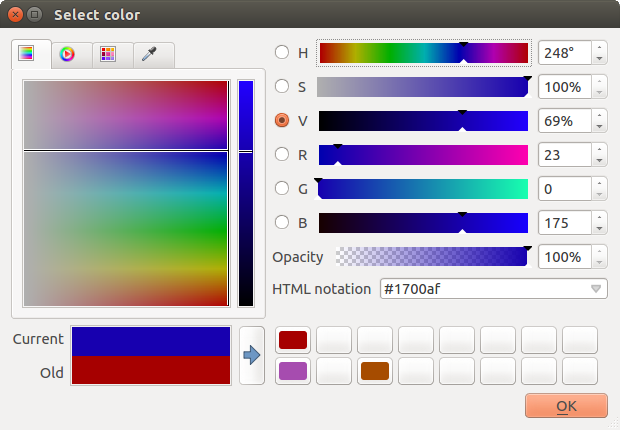
Onglet du sélecteur de couleur
With ![]() color ramp or
color ramp or ![]() color wheel tab,
you can browse to all possible color combinations and apply it to the item.
In the
color wheel tab,
you can browse to all possible color combinations and apply it to the item.
In the ![]() color swatches tab, you can choose from a
preselected list of color palettes:
color swatches tab, you can choose from a
preselected list of color palettes:
- Recent colors,
- Standard colors, a user-defined list of colors set under Settings ‣ Options ‣ Colors menu
- or Project colors, a user-defined list of colors set under Project ‣ Project Properties ‣ Default Styles.
The latest palettes can be modified thanks to the  and
and  buttons at the bottom of the frame.
The ... button nearby the palette combobox also offers several
options to:
Copier, coller, importer ou exporter des couleurs
- create, import or remove color palettes. Check the Show in Color Buttons option to add the custom palette to the color selector widget (see figure_color_selector).
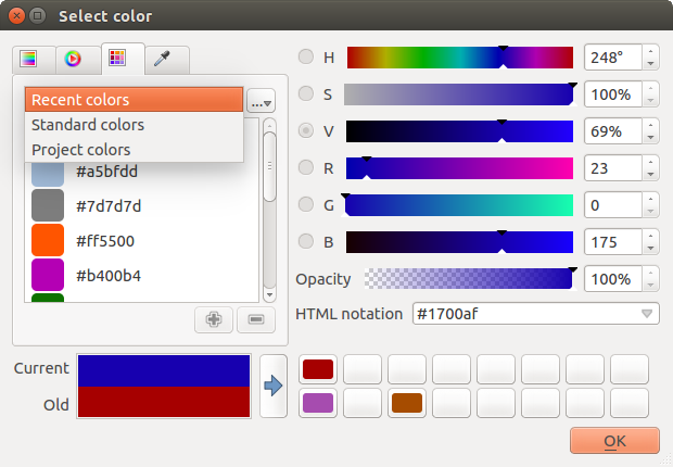
Color selector switcher tab
Another option is to use the ![]() color picker which allows
you to sample a color from under your mouse pointer at any part of
QGIS or even from another application by pressing the space bar. Please note
that the color picker is OS dependent and is currently not supported by macOS.
color picker which allows
you to sample a color from under your mouse pointer at any part of
QGIS or even from another application by pressing the space bar. Please note
that the color picker is OS dependent and is currently not supported by macOS.
Astuce
Modification rapide de la couleur
Click the drop-down arrow at the right of the  color box button
to display a widget for a quick color selection, either in the color wheel or
from existing color palettes. You can also use it to copy or
paste a color.
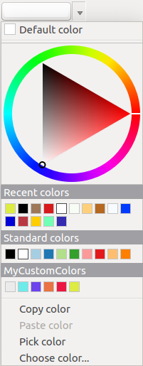
Raccourci pour la sélection de couleur
Modes de fusion
QGIS offers different options for special rendering effects with these tools that you may previously only know from graphics programs. Blending modes can be applied on layers, on features but also on print composer items:
Normal : il s’agit du mode de fusion standard qui utilise la valeur de transparence (canal alpha) du pixel supérieur pour le fusionner avec le pixel sous-jacent, les couleurs ne sont pas mélangées.
Éclaircir : Sélectionne le maximum entre chaque composante depuis les pixels du premier-plan et de l’arrière-plan. Soyez attentif au fait que le résultat obtenu peut présenter un aspect dur et crénelé.
- Screen: Light pixels from the source are painted over the destination, while dark pixels are not. This mode is most useful for mixing the texture of one item with another item (e.g., you can use a hillshade to texture another layer).
- Dodge: Dodge will brighten and saturate underlying pixels based on the lightness of the top pixel. So, brighter top pixels cause the saturation and brightness of the underlying pixels to increase. This works best if the top pixels aren’t too bright; otherwise the effect is too extreme.
- Addition: This blend mode simply adds pixel values of one item with the other. In case of values above one (in the case of RGB), white is displayed. This mode is suitable for highlighting features.
- Darken: This creates a resultant pixel that retains the smallest components of the foreground and background pixels. Like lighten, the results tend to be jagged and harsh.
- Multiply: Here, the numbers for each pixel of the top item are multiplied with the corresponding pixels for the bottom item. The results are darker pictures.
- Burn: Darker colors in the top item cause the underlying items to darken. Burn can be used to tweak and colorise underlying layers.
- Overlay: This mode combines the multiply and screen blending modes. In the resulting picture, light parts become lighter and dark parts become darker.
- Soft light: This is very similar to overlay, but instead of using multiply/screen it uses color burn/dodge. This is supposed to emulate shining a soft light onto an image.
Lumière dure : Ce mode est lui aussi très similaire au mode revêtement. Il est censé émuler une lumière très intense projetée dans l’image.
- Difference: Difference subtracts the top pixel from the bottom pixel, or the other way around, to always get a positive value. Blending with black produces no change, as the difference with all colors is zero.
- Subtract: This blend mode simply subtracts pixel values of one item from the other. In case of negative values, black is displayed.
Zoomer et se déplacer
QGIS fournit des outils pour zoomer et se déplacer vers une zone d’intérêt.
Apart from using the  pan and
  zoom-in /
  zoom-out icons on the toolbar
with the mouse, navigating can also be done with the mouse wheel, spacebar
and the arrow keys. A Zoom factor can be set under the
Settings ‣
  Options ‣ Map tools
menu to define the scale behavior while zooming.
Avec la molette de la souris
You can press the mouse wheel to pan inside of the main window (on macOS, you may need to hold cmd key). You can roll the mouse wheel to zoom in and out on the map; the mouse cursor position will be the center of the zoomed area of interest. Holding down Ctrl while rolling the mouse wheel results in a finer zoom.
Avec les flèches du clavier
Panning the map is possible with the arrow keys. Place the mouse cursor inside the map area, and click on the right arrow key to pan east, left arrow key to pan west, up arrow key to pan north, and down arrow key to pan south.
You can also use the space bar to temporarily cause mouse movements to pan the map. The PgUp and PgDown keys on your keyboard will cause the map display to zoom in or out following the zoom factor set. Pressing Ctrl + or Ctrl - also performs an immediate zoom in/out on the map canvas.
When certain map tools are active (Identify, Measure...), you can perform a zoom by holding down Shift and dragging a rectangle on the map to zoom to that area. This is enabled for the map tools which are not selection tools (since they use Shift for adding to selection) nor edit tools.
Mesurer
Information générale
QGIS propose quatre moyens de mesurer des géométries :
- the interactive measurement tools
 ,
, - measuring in the
 Field Calculator,
 - derived measures in the Identify Features tool,
- and a vector analysis tool: Vector ‣ Geometry Tools ‣ Export/Add Geometry Columns
Les mesures fonctionnent pour les systèmes de coordonnées projetés (par ex. UTM) et non projetés. Les trois premiers outils de mesure utilisent les mêmes options, globales au projet :
- If “on the fly” CRS transformation (see Définir la projection à la volée (ALV)) is enabled, the default measurement metric is - different from most other GIS - ellipsoidal, using the ellipsoid defined in File ‣ Project properties ‣ General. This is true both when geographic and projected coordinate systems are defined for the project.
- If you want to calculate the projected / planimetric area or distance using cartesian maths, the measurement ellipsoid has to be set to “None / Planimetric” (File ‣ Project properties ‣ CRS). However, with a geographic (= unprojected) CRS defined for the data and project, area and distance measurement will be ellipsoidal.
- If “on the fly” CRS transformation is disabled, the measurement metric is planimetric when the project coordinate system is projected and ellipsoidal when the project coordinate system is unprojected / geographic.
However, neither the identify tool nor the field calculator will transform your data to the project CRS before measuring. If you want to achieve this, you have to use the vector analysis tool: Vector ‣ Geometry Tools ‣ Export/Add Geometry Columns. Here, measurement is by default planimetric except if you choose the ellipsoidal measure.
Measure length, areas and angles interactive
Click the  icon in the Attribute toolbar to begin measurements.
The downward arrow near the icon helps you switch to the convenient tool to measure
 length,
  area or
  angle.
The default unit used in the dialog is the one set in Project ‣
Project Properties ‣ General menu.
Note
Configuring the measure tool
While measuring length or area, clicking the Configuration button at the bottom of the widget helps you define in menu Settings ‣ Options ‣ Map Tools the rubberband color, the precision of the measurements and the unit behavior. You can also choose your preferred measurement or angle units but keep in mind that those values are superseded in the current project by options made in Project ‣ Project Properties ‣ General menu.
All measuring modules use the snapping settings from the digitizing module (see section Définir le rayon de tolérance d’accrochage et de recherche). So, if you want to measure exactly along a line feature, or around a polygon feature, first set its layer snapping tolerance. Now, when using the measuring tools, each mouse click (within the tolerance setting) will snap to that layer.
By default,  Measure Line: QGIS measures real distances
between given points according to a defined ellipsoid.
The tool then allows you to click points on the map. Each segment length,
as well as the total, shows up in the measure window.
To stop measuring, click your right mouse button.
Note that you can use the drop-down list near the total to interactively change the measurement units while measuring. This unit is kept for the widget until a new or another project is opened.
The Info section in the dialog explains how calculations are made according to CRS settings available.
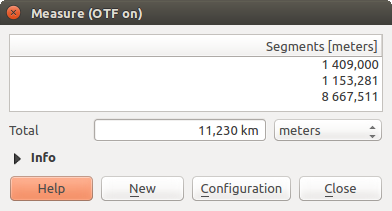
Mesure de distance
 Measure Area: Areas can also be measured. In the
measure window, the accumulated area size appears. Right-click to stop drawing.
The Info section is also available as well as the ability to switch between
different area units.

Mesure d’une aire
 Measure Angle: You can also measure angles. The
cursor becomes cross-shaped. Click to draw the first segment of the angle you
wish to measure, then move the cursor to draw the desired angle. The measure
is displayed in a pop-up dialog.
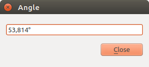
Mesure d’un angle
Sélectionner des entités
QGIS provides several tools to select features in the map canvas. Selection tools are available in View ‣ Select menu or in the Attributes toolbar.
Note
Selection tools work with the currently active layer.
Selecting manually in the map canvas
To select one or several features with the mouse, you can use one of the following tools:
Note
Except the  Select Features by Polygon tool, these
manual selection tools allow you to select feature(s) in the map canvas with a
single click.
While using the  Select Feature(s) tool,
holding Shift or Ctrl toggles whether feature is selected
(ie either adds to the current selection or remove from it).
For the other tools, different behaviors can be performed holding:
- Shift: add features to the current selection
- Ctrl: substract features from the current selection
- Ctrl + Shift: intersect with current selection, ie only keep overlapping features from the current selection
- Alt: select features that are totally within the selection shape. Combined to Shift or Ctrl keys, you can add or substract features to/from the current selection.
Automatic selection
The other selection tools, also available from the Attribute table, perform a selection based on feature’s attribute or its selection state (note that attribute table and map canvas show the same information, so if you select one feature in attribute table, it will be selected in map canvas also):
 Select By Expression... allows user to select
features using expression dialog.
 Deselect Features from All Layers or press
Ctrl+Shift+A to deselect all selected features in all layers.
 Select All Features or press Ctrl+A to select all
features in the current layer.
 Invert Feature Selection to invert the selection in
the current layer.
For example, if you want to find regions that are boroughs from
regions.shp of the QGIS sample data, you can use the ![]() Select features using an Expression icon. Then, you open the
Fields and Values menu and choose the field that you want to query.
Double-click the field ‘TYPE_2’ and also click [Load all unique values]
in the right panel. From the list, choose and double-click ‘Borough’. In the
Expression field, then you’d write the following query:
Select features using an Expression icon. Then, you open the
Fields and Values menu and choose the field that you want to query.
Double-click the field ‘TYPE_2’ and also click [Load all unique values]
in the right panel. From the list, choose and double-click ‘Borough’. In the
Expression field, then you’d write the following query:
"TYPE_2" = 'Borough'
From the expression builder dialog, you can also use the Function list ‣ Recent (Selection) to make a selection that you used before. The dialog remembers the last 20 used expressions. See Expressions chapter for more information and some example.
Astuce
Save your selection into a new file
Users can save selected features into a New Temporary Scratch Layer or a New Vector Layer using Edit ‣ Copy Features and Edit ‣ Paste Features as in the wanted format.
Sélectionner des Entités par Valeur
This selection tool opens the layer’s feature form allowing the user to choose, for each field, which value to look for, if the search should be case sensitive, and the operation that should be used.
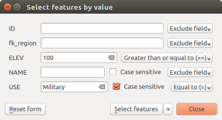
Filter/Select features using form dialog
Alongside each field, there is a drop-down list with the operation options to control the search behaviour. The common options are:
- Exclude Field - The field will not be used for searching
Égal à (=)
- Not equal to
Est manquant (null)
N’est pas manquant (non nul)
For numeric and datetime fields, the additional options are:
Supérieur à (>)
Inférieur à (<)
- Greater than or equal to (>=)
- Less than or equal to (<=)
Entre (inclusif)
- Is not between (inclusive)
For text fields, the additional options are:
Contient
Ne contient pas
For the text options above, it is also possible to use the  Case sensitive option.
After setting all search options, you can use the Select features button to select the matching features. The drop-down options are:
- Select features
Ajouter à la sélection actuelle
Filtrer la sélection courante
Supprimer de la sélection actuelle
You can also clean all search options using the Reset form button.
Valeurs définies par des données
Beside many options in the vector layer properties dialog or settings in the print
composer, you can find a ![]() Data defined override icon.
Thanks to expressions based on layer attributes or item
settings, prebuild or custom functions and variables,
this tool allows you to set dynamic value for the concerned parameter. When enabled,
the value returned by this widget is applied to the parameter regardless its normal
value (checkbox, textbox, slider...).
Data defined override icon.
Thanks to expressions based on layer attributes or item
settings, prebuild or custom functions and variables,
this tool allows you to set dynamic value for the concerned parameter. When enabled,
the value returned by this widget is applied to the parameter regardless its normal
value (checkbox, textbox, slider...).
Clicking the ![]() Data defined override icon shows following entries:
Data defined override icon shows following entries:
- Description... that indicates if the option is enabled, which input is expected, the valid input type and the current definition. Hovering over the widget also pops up these information;
- Field type: an entry to select from the layer’s fields that match the valid input type;
- an entry to list the Variable available;
- Edit... button to create or edit the expression to use;
- Paste and Copy buttons;
le bouton Effacer pour réinitialiser les valeurs.
Parameters that can be used with data-defined tools are:
- Style and symbols parameters
- Labels parameters
- Composer parameters
Identify Features
L’outil Identifier vous permet d’interagir avec le canevas de la carte et d’afficher des informations sur les entités dans un menu contextuel. Pour identifier des entités, vous pouvez :
- View ‣ Identify Features menu,
- or press Ctrl + Shift + I (or
 Cmd + Shift + I),
 - or click the
 Identify Features icon on the Attributes toolbar.
Utiliser l’outil Identifier
QGIS offers two ways to identify features with the  Identify Features tool:
- left click will identify features according to the mode set in the Identify Results panel
- right click will fetch all the snapped features from all the visible layers. This will open a context menu, allowing the user to choose more precisely the features to identify.
Astuce
Choisir les couches à interroger avec l’outil Identifier
Uncheck the Identifiable column in Project ‣
(or  Settings ‣), Project
Properties ‣ Identify layers menu in front of a layer to avoid it
being queried when using the
  Identify Features in a mode
other than Current Layer. This is a handy way to return features from only
layers that are of interest for you.
If you click on feature(s), the Identify Results dialog will list information about the clicked feature(s). The default view is a tree view where the first item is the name of the layer and its children are its identified feature(s). Each feature is described by the name of a field along with its value. This field is the one set in Layer Properties ‣ Display. Then follows all the other information about the feature.
Feature informations
The Identify Results dialog can be customized to display custom fields, but by default it will display three kinds of information:
Actions : Elles sont ajoutées à la fenêtre “Identifier les résultats”. L’action se lance par un clic. Par défaut, une seule action est présente,``Afficher le formulaire de l’entité``. Vous pouvez ajouter d’autres actions à partir de l’onglet des propriétés de la couche (voir Propriétés des Actions).
- Derived: This information is calculated or derived from other information.
This includes:
- general information about the feature and its geometry: feature id, length or perimeter and area in map units depending on its geometry, the count of spatial parts and the number of the clicked part in case of multi-geometry, the count of vertices in the feature and the number of the closest one to the point clicked
- coordinates information: the X and Y (and Z/M if available) coordinate values of the clicked point, the feature closest vertex and its first and last vertices. In case you click on a curved line using the info tool, QGIS will also display the radius of that section in the panel result.
Attributs de données: Il s’agit de la liste des champs et des valeurs de l’entité sur laquelle vous avez cliqué.
Note
Links in feature’s attributes are clickable from the Identify Results panel and will open in your default web browser.
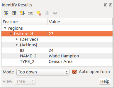
Panneau des résultats de l’identification
Le panneau des résultats de l’identification
At the top of the window, you have seven icons:
 Default behavior to define whether next
identified features information should be collapsed or expanded
 View the feature form
At the bottom of the window, you have the Mode and View comboboxes. With the Mode combobox you can define from which layers features should be identified:
- Current layer : only features from the selected layer are identified. The layer may not be visible in the canvas.
- Top down, stop at first: for only features from the upper visible layer.
- Top down: for all features from the visible layers. The results are shown in the panel.
- and Layer selection: opens a context menu where the user selects the layer to identify features from. Operates like a right-click. Only the chosen features will be shown in the result panel.
Note
Identify tool configuration
You can configure the identify feature in Project ‣ Project Properties in the Identify layers tab. The table allows user to select layer(s) that can be used by this tool to identify features (column Identifiable). You can also put this layer in read-only mode with the checkbox in the last column.
The View can be set as Tree, Table or Graph. ‘Table’ and ‘Graph’ views can only be set for raster layers.
The identify tool allows you to  Auto open a form.
If checked, each time a single feature is identified QGIS will open a form
showing its attributes. This is a handy way to quickly edit a feature’s attributes.
D’autres fonctions peuvent être trouvées dans le menu contextuel d’un élément identifié, via un clic droit. Par exemple, depuis le menu contextuel, vous pouvez :
Voir le formulaire d’entité
Zoomer sur l’entité
Copier l’entité : copie toute la géométrie et les attributs d’une entité
- Toggle feature selection: Adds identified feature to selection
Copier les valeurs d’attributs : copie uniquement les valeurs d’attributs de l’entité identifiée
Copier les attributs de l’entité: Copie les attributs de l’entité
Lâcher les résultats : la fenêtre de résultats est vidée
Masquer la surbrillance : la surbrillance des entités identifiées sur la carte est retirée
Tout mettre en surbrillance
Mettre la couche en surbrillance
Activer une couche : Choisir la couche à activer
Propriétés : ouvre la fenêtre des propriétés de la couche
Tout déplier
Tout replier
Outils d’annotation
The  Text Annotation tool in the attribute
toolbar provides the possibility to place formatted text in a balloon on the
QGIS map canvas. Use the Text Annotation tool and click into the
map canvas.
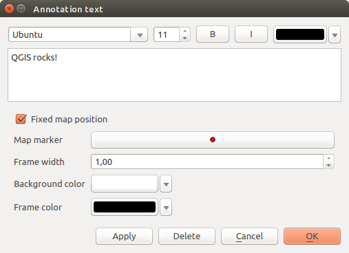
La fenêtre d’annotation de texte
Double clicking on the item opens a dialog with various options. There is the text editor to enter the formatted text and other item settings. For instance, there is the choice of having the item placed on a map position (displayed by a marker symbol) or to have the item on a screen position (not related to the map). The item can be moved by map position (by dragging the map marker) or by moving only the balloon. The icons are part of the GIS theme, and they are used by default in the other themes, too.
The  Move Annotation tool allows you to move the
annotation on the map canvas.
Html annotations
The  Html Annotation tools in the attribute
toolbar provides the possibility to place the content of an html file in a
balloon on the QGIS map canvas. Using the Html Annotation tool,
click into the map canvas and add the path to the html file into the dialog.
SVG annotations
The  SVG Annotation tool in the attribute toolbar
provides the possibility to place an SVG symbol in a balloon on the QGIS map
canvas. Using the SVG Annotation tool, click into the map canvas and
add the path to the SVG file into the dialog.
Form annotations
Additionally, you can also create your own annotation forms. The
 Form Annotation tool is useful to display
attributes of a vector layer in a customized Qt Designer form (see
figure_custom_annotation). This is similar to the designer forms for the
Identify features tool, but displayed in an annotation item.
Also see this video https://youtu.be/0pDBuSbQ02o?t=2m25s from
Tim Sutton for more information.
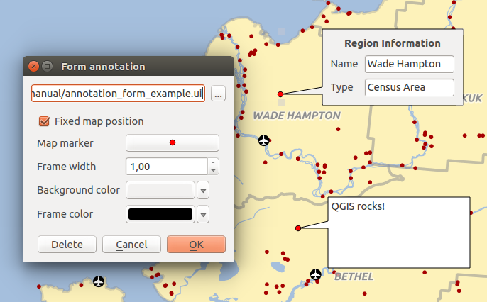
Customized qt designer annotation form
Note
If you press Ctrl+T while an Annotation tool is active (move annotation, text annotation, form annotation), the visibility states of the items are inverted.
Signets spatiaux
Spatial Bookmarks allow you to “bookmark” a geographic location and return to it later. By default, bookmarks are saved on the computer, meaning that they are available from any project in the same computer. If you wish to store the bookmark in the project file (.qgs) then you can do this by selecting the In Project checkbox.
Créer un signet
Pour créer un signet :
Déplacez-vous sur la zone concernée.
- Select the menu option View ‣ New Bookmark or press Ctrl-B. The Spatial Bookmark panel opens with the newly created bookmark.
Entrez un nom pour décrire le signet (jusqu’à 255 caractères).
- Check the In Project box if you wish to save the bookmark in the project file.
Appuyez sur Enter pour ajouter le signet ou cliquer ailleurs.
Notez que vous pouvez avoir plusieurs signets portant le même nom.
Travailler avec les signets
To use or manage bookmarks, select the menu option View ‣ Show Bookmarks. The Spatial Bookmarks panel allows you to:
Zoom sur un signet: sélectionnez le signet souhaité, puis cliquez sur Zoomer jusqu’au signet. Vous pouvez également zoomer sur un signet en double-cliquant dessus.
Supprimer un signet: sélectionnez le signet et cliquez sur Effacer le signet. Confirmez votre choix.
- Import or Export a bookmark: To share or transfer your bookmarks between computers you can use the Import/Export Bookmarks pull down menu in the Spatial Bookmarks dialog. All the bookmarks are transferred.
Inclusion de projets
Sometimes, you’d like to keep in different projects a bunch of layers with the same style. You can either create a default style for these layers or embed them from another project to save you tons of work.
Embed layers and groups from an existing project has some advantages over styling:
- all types of layers (vector or raster, local or online...) can be added
- fetching groups and layers, you can keep the same tree structure of the “background” layers in your different projects
- While the embedded layers are editable, you can’t change their properties such as symbology, labels, forms, default values, actions... This ensures homogeneity throughout the projects
- modify the items in the original project and changes are propagated to all the other projects.
If you want to embed content from other project files into your project, select Layer ‣ Embed Layers and Groups and:
- Press
 to look for a project; you can see the content of the
project (see figure_embed_dialog).
 - Press Ctrl ( or
 Cmd) and click on the layers and
groups you wish to retrieve.
 - Press [OK]. The selected layers and groups are embedded in the Layer panel and can be visualized in the map canvas now. Names of embedded items appear in italic to distinguish them from regular layers and groups.
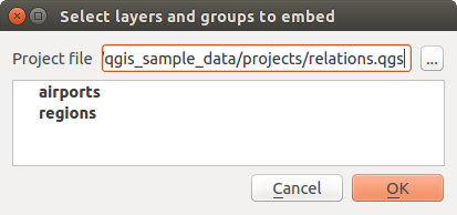
Sélectionner les couches et les groupes à intégrer.
Like any other layer, an embedded layer can be removed from the project by
right-click on the layer and choose  Remove.
Astuce
Change rendering of an embedded layer
It’s not possible to change rendering of an embedded layer, unless you make the changes in the original project file. However, right-click on a layer and select Duplicate creates a layer which is fully-featured and not dependent to the original project. You can then safely remove the linked layer.
Décorations
The Decorations of QGIS include the Grid, the Copyright Label, the North Arrow and the Scale Bar. They are used to ‘decorate’ the map by adding cartographic elements.
Grille
 Grille vous permet d’ajouter un graticule et des coordonnées à la carte.
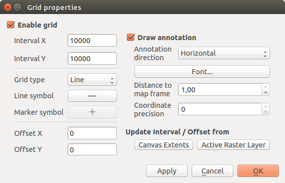
La fenêtre Grille
- Select from menu View ‣ Decorations ‣ Grid. The dialog starts (see figure_decorations_grid).
- Activate the
 Enable grid checkbox and set grid
definitions according to the layers loaded in the map canvas.
 - Activate the
 Draw annotations checkbox and set
annotation definitions according to the layers loaded in the map canvas.
 - Click [Apply] to verify that it looks as expected or [OK] if you’re satisfied.
Étiquette de Copyright
 Copyright label adds a copyright label using the text
you prefer to the map.
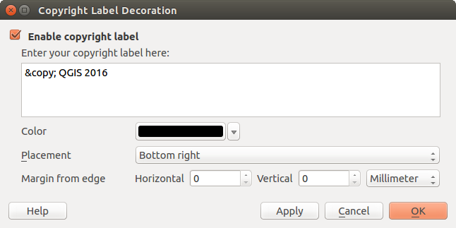
La fenêtre de Copyright
- Select from menu View ‣ Decorations ‣ Copyright Label. The dialog starts (see figure_decorations_copyright).
- Make sure the
 Enable Copyright Label checkbox is
checked.
 - Enter the text you want to place on the map. You can use HTML as shown in the example.
Choisissez l’emplacement de l’étiquette dans la liste déroulante Position
 .
.- You can refine the placement of the item by setting a Horizontal and/or Vertical Marging from (Canvas) Edge. These values can be a distance in Millimeter or Pixels or set as Percentage of the width or height of the map canvas.
- You can change the color to apply.
- Click [Apply] to verify that it looks as expected or [OK] if you’re satisfied.
In the example above, which is the default, QGIS places a copyright symbol followed by the date in the lower right-hand corner of the map canvas.
Flèche du nord
 North Arrow places a simple north arrow on the map canvas.
Currently, there is only one style available. You can adjust the angle of the
arrow or let QGIS set the direction automatically.
If you choose to let QGIS determine the direction, it makes its best guess
as to how the arrow should be oriented.
For placement of the arrow, you have four options, corresponding to
the four corners of the map canvas.
You can refine the placement of the arrow by setting a Horizontal and/or Vertical
Marging from (Canvas) Edge. These values can be a distance in Millimeter or
Pixels or set as Percentage of the width or height of the map canvas.
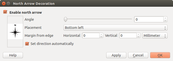
La fenêtre de flèche du nord
Échelle graphique
 Échelle graphique ajoute une simple barre d’échelle sur la carte. Vous choisissez le style, l’emplacement ainsi que les étiquettes de la barre.
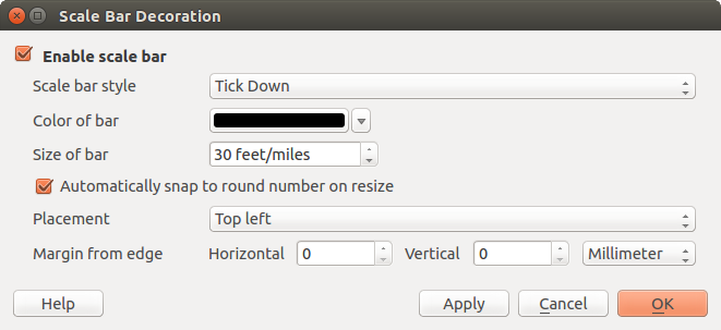
La fenêtre de barre d’échelle
QGIS only supports displaying the scale in the same units as your map frame. So if the units of your layers are in meters, you can’t create a scale bar in feet. Likewise, if you are using decimal degrees, you can’t create a scale bar to display distance in meters.
Pour ajouter une échelle graphique :
- Select from menu View ‣ Decorations ‣ Scale Bar. The dialog starts (see figure_decorations_scale).
- Make sure the
 Enable scale bar checkbox is checked.
 - Choose the style from the Scale bar style
 combo box.
 - Select the color for the bar Color of bar
 or use
the default black color.
 - Set the Size of bar
 .
. - Optionally, check
 Automatically snap to round number
on resize to display values easy-to-read.
 - Choose the placement from the Placement
 combo box.
 - You can refine the placement of the item by setting a Horizontal and/or Vertical Marging from (Canvas) Edge. These values can be a distance in Millimeter or Pixels or set as Percentage of the width or height of the map canvas.
- Click [Apply] to verify that it looks as expected or [OK] if you’re satisfied.
Astuce
Settings of Decorations
When you save a .qgs project, any changes you have made to Grid, North Arrow, Scale Bar and Copyright will be saved in the project and restored the next time you load the project.
Authentification
QGIS has facility to store/retrieve authentication credentials in a secure manner. Users can securely save credentials into authentication configurations, which are stored in a portable database, can be applied to server or database connections, and safely referenced by their ID tokens in project or settings files. For more information see Système d’authentification.
Un mot de passe principal doit être fourni lors de l’initialisation du système d’authentification et de sa base de données portable.
Variables
In QGIS, you can use variables to store useful recurrent values (e.g. the project’s title, or the user’s full name) that can be used in expressions. Variables can be defined at the application’s global level, project level, layer level, composition level, and composer’s item level. Just like CSS cascading rules, variables can be overwritten - e.g., a project level variable will overwrite any application’s global level variables set with the same name. You can use these variables to build text strings or other custom expressions using the @ character before the variable name. For example in composer creating a label with this content:
This map was made using QGIS [% @qgis_version %]. The project file for this
map is: [% @project_path %]
Rendra l’étiquette comme ceci:
This map was made using QGIS 2.14. The project file for this map is:
/gis/qgis-user-conference-2015.qgs
Besides the preset read-only variables, you can define your own custom variables for any of the levels mentioned above. You can manage:
- global variables from the Settings ‣ Options menu;
- project’s variables from Project properties (see Propriétés du projet);
- vector layer’s variables from the Layer Properties dialog (see Fenêtre Propriétés d’une couche vecteur);
- composition’s variables from the Composition panel in the Print composer (see Composition Panel);
- and composer item’s variables from the Item properties panel in the Print composer (see Composer Items Common Options).
To differentiate from editable variables, read-only variable’s names and values are emphasized in italic. On the other hand, higher level variables overwritten by lower level ones are strike through.
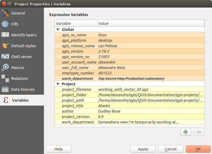
Variables editor at the project’s level
Note
You can read more about variables and find some examples in Nyall Dawson’s Exploring variables in QGIS 2.12, part 1, part 2 and part 3 blog posts.


