Creating Layers
Layers can be created in many ways, including:
empty layers from scratch;
layers from existing layers;
layers from the clipboard;
layers as a result of an SQL-like query based on one or many layers: the virtual layer.
QGIS also provides tools to import/export different formats.
Creating new vector layers
QGIS allows you to create new Shapefile layers, new SpatiaLite layers, new GPX layers and new Temporary Scratch layers. Creation of a new GRASS layer is supported within the GRASS plugin. (Please refer to section Creating a new GRASS vector layer for more information on creating GRASS vector layers.)
Creating a new GeoPackage layer
To create a new GeoPackage layer go to
 .
The New GeoPackage Layer dialog will
be displayed as shown in figure_create_geopackage.
.
The New GeoPackage Layer dialog will
be displayed as shown in figure_create_geopackage.
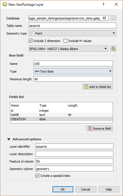
Creating a New GeoPackage layer dialog
The first step is to select an existing GeoPackage or create a new one. This can be done by pressing the ellipses … button at the right of the Database field. Then, give a name for the new layer, define the layer type and specify the coordinate reference system with Specify CRS.
To define an attribute table for the new GeoPackage layer, add the names of the attribute columns you want to create with the corresponding column type, and click on the Add to Fields List button. Once you are happy with the attributes, click OK. QGIS will automatically add the new layer to the legend, and you can edit it in the same way as described in section Digitizing an existing layer.
Creating a new Shapefile layer
To create a new Shapefile layer, choose
 from the
menu or select it from the Data Source Manager
toolbar. The New Shapefile Layer dialog will be
displayed as shown in figure_create_shapefile.
The first step is to provide a path and name for the Shapefile. QGIS will
automatically add the
from the
menu or select it from the Data Source Manager
toolbar. The New Shapefile Layer dialog will be
displayed as shown in figure_create_shapefile.
The first step is to provide a path and name for the Shapefile. QGIS will
automatically add the .shp extension to the name you specify
Next, choose the type of layer (point, line or polygon) and optional Z or M
dimensions, as well as the CRS (coordinate reference system).
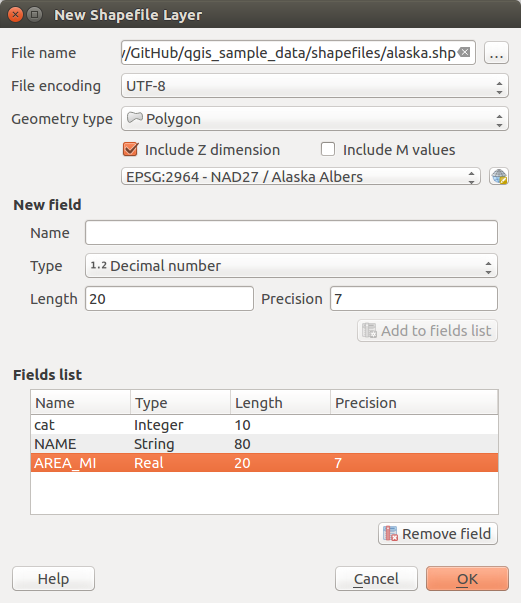
Creating a new Shapefile layer dialog
To complete the creation of the new Shapefile layer, add the desired attributes
by specifying a name and type for each attribute and clicking on the
Add to Fields List button.
A first ‘id’ column is added by default but can be
removed, if not wanted. Only Decimal number  ,
Whole number , Text data
and Date attributes are
supported. Additionally, depending on the attribute type, you can also define
the length and precision of the new attribute column. Once you are happy with the
attributes, click OK.
Once the Shapefile has been created, it will be added to the map as a new layer,
and you can edit it in the same way as described in section Digitizing an existing layer.
,
Whole number , Text data
and Date attributes are
supported. Additionally, depending on the attribute type, you can also define
the length and precision of the new attribute column. Once you are happy with the
attributes, click OK.
Once the Shapefile has been created, it will be added to the map as a new layer,
and you can edit it in the same way as described in section Digitizing an existing layer.
Creating a new SpatiaLite layer
To create a new SpatiaLite layer for editing, choose  from the
menu or select it from the Data Source Manager
toolbar.
The New SpatiaLite Layer dialog will be displayed as shown in
Figure_create_spatialite.
from the
menu or select it from the Data Source Manager
toolbar.
The New SpatiaLite Layer dialog will be displayed as shown in
Figure_create_spatialite.
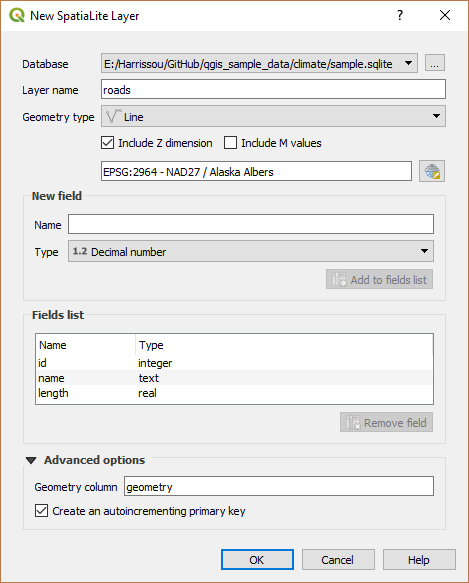
Creating a New SpatiaLite layer dialog
The first step is to select an existing SpatiaLite database or to create a new
SpatiaLite database. This can be done with the … button at
the right of the database field. Then, add a name for the new layer, define
the layer type, and specify the coordinate reference system with Specify CRS.
If desired, you can select  Create an autoincrementing primary key.
To define an attribute table for the new SpatiaLite layer, add the names of the attribute columns you want to create with the corresponding column type, and click on the Add to Fields List button. Once you are happy with the attributes, click OK. QGIS will automatically add the new layer to the legend, and you can edit it in the same way as described in section Digitizing an existing layer.
Further management of SpatiaLite layers can be done with the DB Manager. See DB Manager Plugin.
Creating a new GPX layer
To create a new GPX file, you need to load the GPS plugin first.
 opens the Plugin Manager Dialog. Activate the
GPS Tools checkbox.
opens the Plugin Manager Dialog. Activate the
GPS Tools checkbox.
When this plugin is loaded, choose  from the menu.
In the Save new GPX file as dialog, choose where to save the
new file and press Save. Three new layers are added to the
Layers Panel:
from the menu.
In the Save new GPX file as dialog, choose where to save the
new file and press Save. Three new layers are added to the
Layers Panel: waypoints, routes and tracks with
predefined structure.
Creating a new Temporary Scratch Layer
Temporary Scratch Layers are in-memory layers, meaning that they are not saved on disk and will be discarded when QGIS is closed. They can be handy to store features you temporarily need or as intermediate layers during geoprocessing operations.
Empty, editable temporary scratch layers can be defined using  or New temporary scratch layer button from the Data
Source Manager Toolbar. Here you can create a:
or New temporary scratch layer button from the Data
Source Manager Toolbar. Here you can create a:
No geometrytype layer, served as simple table,PointorMultiPointlayer,LineString/CompoundCurveorMultiLineString/MultiCurvelayer,Polygon/CurvePolygonorMultiPolygon/MultiSurfacelayer.
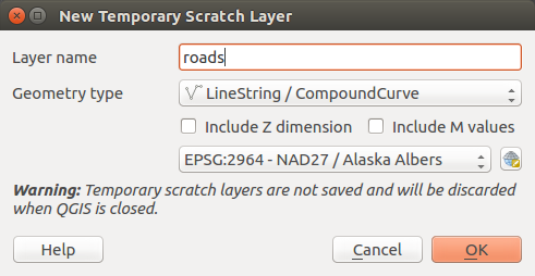
Creating a new Temporary Scratch layer dialog
By default, a new temporary scratch layer is created without any attribute. But you can also create prepopulated temporary scratch layers using e.g. the clipboard (see Creating new layers from the clipboard) or as a result of a Processing algorithm.
Tip
Permanently store a memory layer on disk
To avoid data loss when closing project with temporary scratch layers, you can save these layers to any vector format supported by QGIS:
clicking the
 indicator icon next to the layer;
selecting the Make permanent entry in the layer contextual menu;
or as of any other vector layer, using the entry from the contextual menu or the menu.
Each of these commands prompts the Save Vector Layer as dialog exposed in Creating new layers from an existing layer section and the saved file replaces the temporary one in the Layers panel.
Creating new layers from an existing layer
Both raster and vector layers can be saved in a different format and/or reprojected to a different coordinate reference system (CRS) using the menu or right-clicking on the layer in the Layers panel and selecting:
for raster layer
or for vector layer.
Drag’n drop layer from the layer tree to the PostGIS entry in the Browser Panel. Note that you should have already a PostGIS connection in the Browser Panel.
Common parameters
The Save Layer as… dialog shows several parameters to change the behavior when saving the layer. Among the common parameters for raster and vector are:
File name
CRS: can be changed to reproject the data
Add saved file to map: to add the new layer to the canvas
Extent (possible values are layer, Map view or user-defined extent)
However, some parameters are specific to raster and vector formats:
Raster specific parameters
Depending on the format of export, some of these options may not be available:
Output mode (it can be raw data or rendered image)
Format: exports to any raster format GDAL can write to, such as GeoTiff, GeoPackage, MBTiles, Geospatial PDF, SAGA GIS Binary Grid, Intergraph Raster, ESRI .hdr Labelled…
Resolution
Create Options: use advanced options (file compression, block sizes, colorimetry…) when generating files, either from the predefined create profiles related to the output format or by setting each parameter.
Pyramids creation
VRT Tiles in case you opted to
Create VRTNo data values
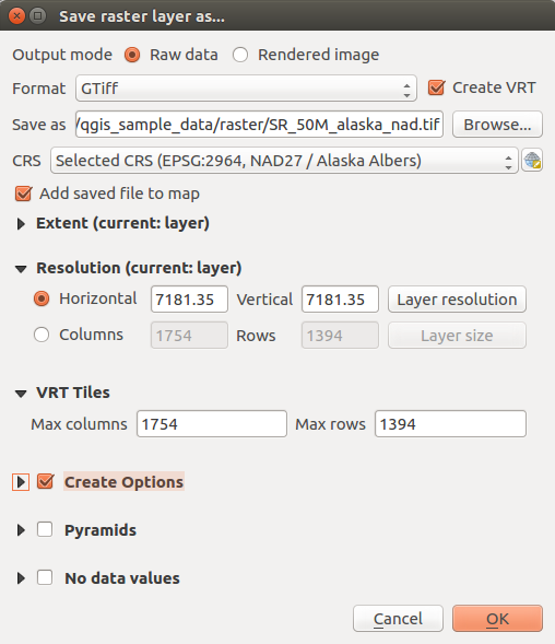
Saving as a new raster layer
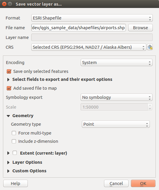
Vector specific parameters
Depending on the format of export, some of these options are available or not:
Format: exports to any vector format GDAL can write to, such as GeoPackage, ESRI Shapefile, AutoCAD DXF, ESRI FileGDB, Mapinfo TAB or MIF, SpatiaLite, CSV, KML, ODS…
Layer name depending on the selected format
Encoding
Save only selected features
Select fields to export and their export options. In case you set your fields behavior with some Edit widgets, e.g.
value map, you can keep the displayed values in the layer by checking Replace all selected raw fields values by displayed
values.Symbology export: can be used mainly for DXF export and for all file formats who manage OGR feature styles (see note below) as DXF, KML, tab file formats:
No symbology: default style of the application that reads the data
Feature symbology: save style with OGR Feature Styles (see note below)
Symbol Layer symbology: save with OGR Feature Styles (see note below) but export the same geometry multiple times if there are multiple symbology symbol layers used
A Scale value can be applied to the latest options.
Note
OGR Feature Styles are a way to store style directly in the data as a hidden attribute. Only some formats can handle this kind of information. KML, DXF and TAB file formats are such formats. For advanced users, you can read the OGR Feature Styles specification document.
Geometry: you can configure the geometry capabilities of the output layer
geometry type: keeps the original geometry of the features when set to Automatic, otherwise removes or overrides it with any type. You can add an empty geometry column to an attribute table, remove the geometry column of a spatial layer.
Force multi-type: forces creation of multi-geometry features in the layer.
Include z-dimension to geometries.
Tip
Overriding layer geometry type makes it possible to do things like save a
geometryless table (e.g. .csv file) into a shapefile WITH any type of
geometry (point, line, polygon), so that geometries can then be manually added
to rows with the  Add Part tool.
Datasources Options, Layer Options or Custom Options which allow you to configure some advanced parameters. See the gdal-ogr driver documentation.
Saving as a new vector layer
When saving a vector layer into an existing file, depending on the capabilities of the output format (Geopackage, SpatiaLite, FileGDB…), the user can decide whether to:
overwrite the whole file
overwrite only the target layer (the layer name is configurable)
append features to the existing target layer
append features, add new fields if there are any.
For formats like ESRI Shapefile, MapInfo .tab, feature append is also available.
Creating new DXF files
Besides the Save As… dialog which provides options to export a
single layer to another format, including *.DXF, QGIS provides another
tool to export multiple layers as a single DXF layers. It’s accessible in the
menu.
In the DXF Export dialog:
Indicate the destination layer file.
Choose the symbology mode and scale (see the OGR Feature Styles note) if applicable.
Select the data Encoding.
Select the CRS to apply: the selected layers will be reprojected to the given CRS.
select the layers to include in the DXF files either by checking each in the table widget or automatically pick them from an existing map theme. The Select All and Deselect All buttons can also help to quickly set the data to export.
For each layer, you can also choose whether to export all the features in a single DXF layer or rely on a field whose values are used to split the features in generated destination layers in the DXF output.
Optionally, you can also choose to:
- Use the layer title as name if set instead of the
layer name itself;
- Export features intersecting the current map extent;
 Force 2d output (eg. to support polyline width);
- Export label as MTEXT elements or TEXT elements.
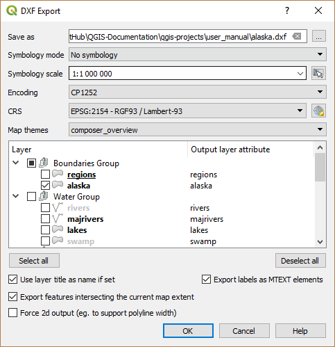
Exporting a project to DXF dialog
Creating new layers from the clipboard
Features that are on the clipboard can be pasted into a new layer. To do this, Select some features, copy them to the clipboard, and then paste them into a new layer using and choosing:
New Vector Layer…: you need to select the layer CRS, poping up the Save vector layer as… dialog from which you can select any supported data format (see Creating new layers from an existing layer for parameters);
or Temporary Scratch Layer…: you need to select the layer CRS and give a name.
A new layer, filled with selected features and their attributes is created and added to map canvas if asked.
Note
Creating layers from clipboard is possible with features selected and copied within QGIS as well as features from another application, as long as they are defined using well-known text (WKT) string.
Creating virtual layers
Virtual layers are a special kind of vector layer. They allow you to define a layer as the result of an SQL query involving any number of other vector layers that QGIS is able to open. Virtual layers do not carry data by themselves and can be seen as views to other layers.
To create a virtual layer, open the virtual layer creation dialog by:
clicking
 Add Virtual Layer option in the
menu;
Add Virtual Layer option in the
menu;enabling the
Add Virtual Layer tab in the
Data Source Manager dialog;or using the DB Manager dialog tree item.
The dialog allows you to specify a Layer name and an SQL Query. The query can use the name (or id) of loaded vector layers as tables, as well as their field names as columns.
For example, if you have a layer called airports, you can create a new
virtual layer called public_airports with an SQL query like:
SELECT *
FROM airports
WHERE USE = "Civilian/Public"
The SQL query will be executed, regardless of the underlying provider of the
airports layer, even if this provider does not directly support SQL
queries.
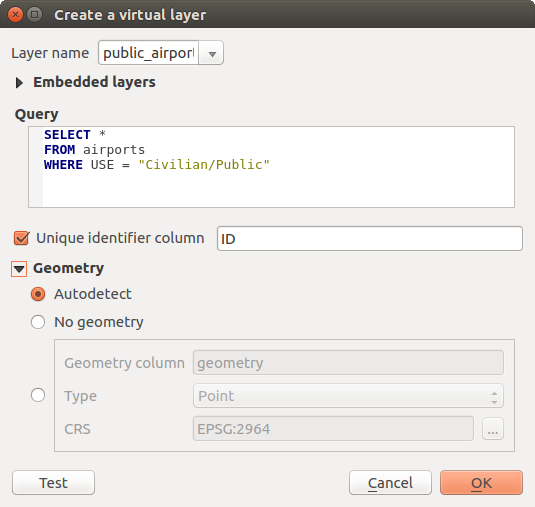
Create virtual layers dialog
Joins and complex queries can also be created, for example, to join airports and country information:
SELECT airports.*, country.population
FROM airports
JOIN country
ON airports.country = country.name
Note
It’s also possible to create virtual layers using the SQL window of DB Manager Plugin.
Embedding layers for use in queries
Besides the vector layers available in the map canvas, the user can add layers to the Embedded layers list, which he can use in queries without the need to have them showing in the map canvas or Layers panel.
To embed a layer, click Add and provide the Local name, Provider, Encoding and the path to the Source.
The Import button allows adding layers loaded in the map canvas into the Embedded layers list. This allows to later remove those layers from the Layers panel without breaking any existent query.
Supported query language
The underlying engine uses SQLite and SpatiaLite to operate.
It means you can use all of the SQL your local installation of SQLite understands.
Functions from SQLite and spatial functions from SpatiaLite can also be used in a virtual layer query. For instance, creating a point layer out of an attribute-only layer can be done with a query similar to:
SELECT id, MakePoint(x, y, 4326) as geometry
FROM coordinates
Functions of QGIS expressions can also be used in a virtual layer query.
To refer the geometry column of a layer, use the name geometry.
Contrary to a pure SQL query, all the fields of a virtual layer query must
be named. Don’t forget to use the as keyword to name your columns if they
are the result of a computation or function call.
Performance issues
With default parameters set, the virtual layer engine will try its best to detect the type of the different columns of the query, including the type of the geometry column if one is present.
This is done by introspecting the query when possible or by fetching the first row of the query (LIMIT 1) at last resort. Fetching the first row of the result just to create the layer may be undesirable for performance reasons.
The creation dialog allows to specify different parameters:
Unique identifier column: this option allows specifying which field of the query represents unique integer values that QGIS can use as row identifiers. By default, an autoincrementing integer value is used. Defining a unique identifier column allows to speed up the selection of rows by id.
No geometry: this option forces the virtual layer to ignore any geometry field. The resulting layer is an attribute-only layer.
Geometry Column: this option allows to specify the name of the column that is to be used as the geometry of the layer.
Geometry Type: this option allows to specify the type of the geometry of the virtual layer.
Geometry CRS: this option allows to specify the coordinate reference system of the virtual layer.
Special comments
The virtual layer engine tries to determine the type of each column of the query. If it fails, the first row of the query is fetched to determine column types.
The type of a particular column can be specified directly in the query by using some special comments.
The syntax is the following: /*:type*/. It has to be placed just after
the name of a column. type can be either int for integers, real
for floating point numbers or text.
For instance:
SELECT id+1 as nid /*:int*/
FROM table
The type and coordinate reference system of the geometry column can also be set
thanks to special comments with the following syntax /*:gtype:srid*/ where
gtype is the geometry type (point, linestring, polygon,
multipoint, multilinestring or multipolygon) and srid an
integer representing the EPSG code of a coordinate reference system.
Use of indexes
When requesting a layer through a virtual layer, indexes of this source layer will be used in the following ways:
if an
=predicate is used on the primary key column of the layer, the underlying data provider will be asked for a particular id (FilterFid)for any other predicates (
>,<=,!=, etc.) or on a column without a primary key, a request built from an expression will be used to request the underlying vector data provider. It means indexes may be used on database providers if they exist.
A specific syntax exists to handle spatial predicates in requests and triggers
the use of a spatial index: a hidden column named _search_frame_ exists
for each virtual layer. This column can be compared for equality to a bounding
box. Example:
SELECT *
FROM vtab
WHERE _search_frame_=BuildMbr(-2.10,49.38,-1.3,49.99,4326)
Spatial binary predicates like ST_Intersects are significantly sped up when
used in conjunction with this spatial index syntax.