` `
Editierfunktionen
- Einstellen der Fangtoleranz und des Suchradius
- Topologisches Editieren
- Einen vorhandenen Layer editieren
- Erweiterte Digitalisierung
- Rückgängig und Wiederholen
- Objekt(e) drehen
- Objekt vereinfachen
- Teil hinzufügen
- Teil löschen
- Ring hinzufügen
- Ring füllen
- Ring löschen
- Objekte überarbeiten
- Linie versetzen
- Objekte trennen
- Teile zerlegen
- Gewählte Objekte verschmelzen
- Attribute gewählter Objekte vereinen
- Punktsymbole drehen
- Offset Point Symbols
- Automatische Verfolgung
- Das erweiterte Digitalisierungsfenster
QGIS supports various capabilities for editing OGR, SpatiaLite, PostGIS, MSSQL Spatial and Oracle Spatial vector layers and tables.
Bemerkung
Die Vorgehensweise GRASS Layer zu bearbeiten ist anders - siehe Abschnitt Digitalisieren und Editieren eines GRASS Vektorlayers für Details.
Tipp
Zeitgleiches Editieren
Diese Version von QGIS kontrolliert nicht, ob noch jemand ein Objekt zur gleichen Zeit editiert wie Sie. Die zuletzt schreibende Person gewinnt.
Einstellen der Fangtoleranz und des Suchradius
Für eine optimale und präzise Bearbeitung der Vektorlayer Geometrien, müssen wir für Objektknoten einen entsprechenden Wert von Fangtoleranz und den Suchradius einzustellen.
Fangtoleranz
Snapping tolerance is the distance QGIS uses to search for the closest vertex and/or segment you are trying to connect to when you set a new vertex or move an existing vertex. If you aren’t within the snapping tolerance, QGIS will leave the vertex where you release the mouse button, instead of snapping it to an existing vertex and/or segment. The snapping tolerance setting affects all tools that work with tolerance.
Eine globale, projektweite Fangtoleranz kann definiert werden indem Sie Einstellungen ‣
 Optionen auswählen. Im Menü Digitalisierung können Sie zwischen ‘zum Stützpunkt’, ‘zum Segment’ oder ‘Zum Stützpunkt und Segment’ als Standard Fangmodus wählen. Sie können auch eine Voreingestellte Fangtoleranz und einen Suchradius für die Stützpunktbearbeitung definieren. Die Toleranz kann entweder in Karteneinheiten oder in Pixeln eingestellt werden. Der Vorteil wenn man Pixel wählt ist dass die Fangtoleranz sich nicht nach Zoomoperationen verändert. In unserem kleinen Digitalisierprojekt (Arbeiten mit dem Alaskadatensatz) definieren wir die Fangeinheiten in Fuß. Ihre Ergebnisse können variieren etwas in der Größenordnung von 300 ft bei einem Maßstab von 1:10000 sollte eine hinreichende Einstellung sein.
- A layer-based snapping tolerance that overrides the global snapping options
can be defined by choosing Settings ‣ Snapping options.
It enables and adjusts snapping mode
and tolerance on a layer basis (see figure_edit_snapping ). This dialog offers
three different modes to select the layer(s) to snap to:
Aktueller Layer: nur der aktuelle Layer wird genutzt, eine praktische Möglichkeit die Topologie abzusichern, während der Layer bearbeitet wird
Alle Layer: eine schnelle und einfache Einstellung für alle sichtbaren Layer in dem Projekt, sodass der Zeiger alle Ecken und/oder Segmente fängt. In den meisten Fällen reicht es aus, diesen Fangmodus zu verwenden.
Erweitert: Wenn Sie einen Layer bearbeiten wollen und dass seine Stützpunkte zu einem anderen Layer snappen sollen, dann aktivieren Sie das Fangen nur auf den zu snappenden Layer und verringern Sie die globale Fangtoleranz auf einen kleineren Wert. Darüberhinaus wird das Fangen nicht mit einem Layer funktionieren der nicht im Fangoptionen Dialog aktiviert ist, was unabhängig von der globalen Fangtoleranz funktioniert. Vergewissern Sie sich also dass das Kontrollkästchen für die Layer auf die Sie snappen wollen aktiviert ist.
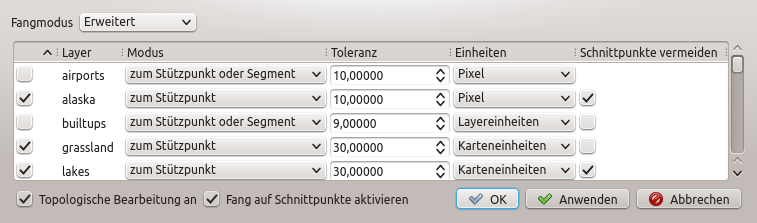
Das Bearbeiten von Snappingoptionen auf Layerbasis (Fortgeschrittener Modus)
Tipp
Steuern Sie die Liste der zu fangenden Layer
Der Dialog Fangoptionen ist standardmäßig mit Parametern bevölkert (Modus, Toleranz, Einheiten) die in dem Reiter Digitalisierung einzustellen sind. Um zu vermeiden, dass Layer standardmäßig überprüft werden im Erweiterten Modus und daher fangbar eingestellt sind, setzen Sie den Standard Fangmodus auf Aus.
Die Fangtoleranz kann in Pixeln oder Karteneinheiten (die Einheit der Kartenansicht) eingestellt werden. Während dem Erweiterten Layer Auswahlmodus, möglich ist eine Fangtoleranz zu nutzen die sich auf die Layereinheiten bezieht, die Einheiten des reprojizierten Layers, wenn ‘on-the-fly’ Transformation aktiviert ist.
Suchradius
Search radius is the distance QGIS uses to search for the closest vertex
you are trying to select when you click on the map. If you aren’t within the
search radius, QGIS won’t find and select any vertex for editing.
The search radius for vertex edits can be defined under Settings ‣
Options ‣ Digitizing tab. This is the same
place where you define the general, project-wide snapping tolerance.
Snap tolerance and search radius are set in map units or pixels, so you may find you need to experiment to get them set right. If you specify too big of a tolerance, QGIS may snap to the wrong vertex, especially if you are dealing with a large number of vertices in close proximity. Set search radius too small, and it won’t find anything to move.
Topologisches Editieren
Abgesehen von der Einstellung des layerbasierten Fangmodus können im Menü Einstellungen ‣ Fangoptionen... (oder Datei ‣ Fangoptionen) auch topologische Funktionen aktiviert werden. Hier können Sie  Topologische Bearbeitung an definieren und/oder für Polygonlayer können Sie die Spalte Überschn. verm. aktivieren.
Topologisches Editieren ermöglichen
Die Option Topologische Bearbeitung an dient dem Bearbeiten und Aufrechterhalten von gemeinsamen Grenzen in Objektmosaiken. QGIS ‘erkennt’ gemeinsame Grenzen in Objektmosaiken so, dass Sie einfach den Stützpunkt einmal verschieben müssen und QGIS dann die Aufgabe übernimmt die benachbarten Objekte zu updaten.
Überschneidung neuer Polygone vermeiden
Die zweite topologische Option genannt Überschneidungen vermeiden verhindert ein Zeichnen von Objekten über ein existierendes. Es dient dazu aneinanderhängende Polygone schneller zu digitalisieren. Wenn Sie bereits ein Polygon erstellt haben ist es mit dieser Option möglich das zweite zu digitalisieren, so dass beide sich überschneiden und QGIS schneidet dann das zweite Polygon gemäß der gemeinsamen Grenze aus. Der Vorteil ist dass Sie nicht alle Stützpunkte der gemeinsamen Grenze digitalisieren müssen.
Bemerkung
Wenn die neue Geometrie vollständig durch bestehende abgedeckt ist, wird sie gelöscht und die neue Funktion wird keine Geometrie haben, wenn vom Anbieter erlaubt, ansonsten werden gespeicherte Änderungen eine QGIS Pop-up Fehlermeldung erzeugen.
Warnung
Überschneidungen vermeiden Option Vorsichtig nutzen
Da die Option Geometrien jedes überschneidenden Objekt jedes Polygonlayers schneidet oder löscht, vergessen Sie nicht, diese Option bei Nichtbenutzung zu deaktivieren, andererseits können Sie unerwartete Geometrien erhalten.
Fang auf Schnittpunkte aktivieren
Ein andere Möglichkeit stellt das Fang auf Schnittpunkte aktivieren dar. Sie können damit auf einen Schnittpunkt von Hintergrundlayern snappen selbst wenn es keinen Stützpunkt auf dem Schnittpunkt gibt.
Geometrieprüfung
Ein Kern-Plugin, dass dem Anwender hilft, Geometrieungültigkeiten zu finden. Weitere Informationen über diese Plugin erhalten Sie unter Geometrieprüfung Plugin.
Einen vorhandenen Layer editieren
By default, QGIS loads layers read-only. This is a safeguard to avoid accidentally editing a layer if there is a slip of the mouse. However, you can choose to edit any layer as long as the data provider supports it (see Exploring Data Formats and Fields), and the underlying data source is writable (i.e., its files are not read-only).
Tipp
Restrict edit permission on layers within a project
From the Project ‣ Project properties ‣ Identify tab, You can choose to set any layer read-only regardless the provider permission. This can be a handy way, in a multi-users environment to avoid unauthorized users to mistakenly edit layers (e.g., shapefile), hence potentially corrupt data. Note that this setting only applies inside the current project.
In general, tools for editing vector layers are divided into a digitizing and an advanced digitizing toolbar, described in section Erweiterte Digitalisierung. You can select and unselect both under View ‣ Toolbars ‣. Using the basic digitizing tools, you can perform the following functions:
| Icon | Funktion |
Icon | Funktion |
|---|---|---|---|
 |
Aktuelle Änderungen |
 |
Bearbeitungsstatus umschalten |
 |
Objekt hinzufügen: Punkt hinzufügen |
 |
Objekt hinzufügen: Linie hinzufügen |
 |
Objekt hinzufügen: Polygon hinzufügen |
 |
Move Feature |
 |
Add Circular String |  |
Add Circular String By Radius |
 |
Node Tool |  |
Ausgewähltes Löschen |
 |
Ausgewählte Objekte ausschneiden |
 |
Objekte kopieren |
 |
Objekte einfügen |
 |
Layeränderungen speichern |
Tabelle Bearbeiten: Funktionen der Werkzeugleiste Digitalisierung
Beachten Sie, dass Sie während der Nutzung des Digitalisierungswerkzeugs, weiterhin in dem Kartenfenster zoomen oder ziehen können, ohne den Fokus auf das Werkzeug zu verlieren.
All editing sessions start by choosing the Toggle editing
option found in the context menu of a given layer, from the attribute table dialog, the
digitizing toolbar or the Edit menu.
Sobald der Layer im Bearbeitungsmodus ist, werden zusätzliche Werkzeuge verfügbar und Markierungen an den Eckpunkten alles Objekte erscheinen, bis Sie die Markierungen nur für gewählte Objekte anzeigen Option unter Einstellungen ‣ Optionen... ‣ Digitalisierung aktiviert haben.
Tipp
Regelmäßiges Sichern der Daten
Denken Sie daran Layeränderungen regelmäßig zu speichern. Dies überprüft auch dass Ihre Datenquelle alle Änderungen akzeptiert.
Objekte digitalisieren
You can use the Add Feature,
Add Feature or
Add Feature icons on the toolbar to add new feature (point, line and
polygon) into the current layer.
The next buttons Add circular string or
Add circular string by radius allow users to add
line or polygon features with a circular geometry.
To create features with these tools, you first digitize the geometry then enter its attributes. To digitize the geometry, left-click on the map area to create the first point of your new feature.
For linear or curved geometries, keep on left-clicking for each additional point you wish to capture or use automatic tracing capability to accelerate the digitization. You can switch back and forth between linear Add feature tool and curved Add circular string... tools to create compound curved geometry. Pressing Delete or Backspace key reverts the last node you add. When you have finished adding points, right-click anywhere on the map area to confirm you have finished entering the geometry of that feature.
Bemerkung
Gebogene Geometrien sind als solche nur in kompatiblen Datenanbieter gespeichert
Although QGIS allows to digitize curved geometries within any editable data format, you need to be using a data provider (e.g. PostGIS, GML or WFS) that supports curves to have features stored as curved, otherwise QGIS segmentizes the circular arcs. The memory layer provider also supports curves.
Tipp
Das Digitalisierungsgummiband anpassen
Während dem Erfassen von Polygonen, kann das voreingestellte rote Band unterliegende Objekte oder Orte verstecken, um einen Punkt zu erfassen. Dies kann durch Einstellen einer geringeren Opazität (oder Alpha-Kanal) des Bands ausgebessert werden Farbe füllen im Menü Einstellungen ‣ Optionen ‣ Digitalisierung. Sie können auch die Verwendung des Gummibands vermeiden Don’t update rubber band during node editing.
The attribute window will appear, allowing you to enter the information for the new feature. Figure_edit_values shows setting attributes for a fictitious new river in Alaska. However, in the Digitizing menu under the Settings ‣ Options menu, you can also activate:
- Suppress attributes pop-up windows after each created
feature to avoid the form opening
oder
Letzte Attributwerteingaben wiederverwenden um Felder beim Öffnen automatisch gefüllt zu haben und nur ändernde Werte zu korrigieren.
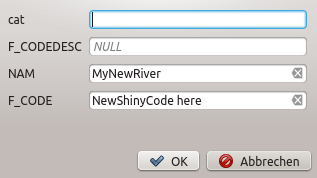
Der Attributwertedialog nach dem Digitalisieren eines neuen Vektorobjekts
With the Move Feature(s) icon on the toolbar, you can
move existing features.
Node Tool
For shapefile-based or MapInfo layers as well as SpatiaLite, PostgreSQL/PostGIS,
MSSQL Spatial, and Oracle Spatial tables, the
Node Tool provides manipulation capabilities of
feature vertices similar to CAD programs. It is possible to simply select
multiple vertices at once and to move, add or delete them altogether.
The node tool also works with ‘on the fly’ projection turned on and supports
the topological editing feature. This tool is, unlike other tools in
QGIS, persistent, so when some operation is done, selection stays
active for this feature and tool.
Es ist wichtig die Eigenschaften unter menuselection:Einstellungen –> Optionen ‣ Digitalisierung ‣ Suchradius:  auf eine Zahl größer als Null einzustellen. Andernfalls ist QGIS nicht in der Lage mitzuteilen welcher Stützpunkt bearbeitet werden soll und wird einen Warnhinweis zeigen.
Tipp
Stützpunktmarken
Die aktuelle Version von QGIS unterstützt drei Arten von Stützpunktmarkern:’Teiltransparenter Kreis’, ‘Kreuz’ und ‘Keine’. Um den Markierungsstil zu ändern wählen Sie Optionen aus dem Einstellungen Menü, klicken Sie auf das Digitalisierung Menü und wählen Sie den entsprechenden Eintrag.
Eine einfache Übung
Start by activating the Node Tool and selecting a
feature by clicking on it. Red boxes will appear at each vertex of this feature.
- Selecting vertices: You can select vertices by clicking on them one at a time, by clicking on an edge to select the vertices at both ends, or by clicking and dragging a rectangle around some vertices. When a vertex is selected, its color changes to blue. To add more vertices to the current selection, hold down the Ctrl key while clicking. Hold down Ctrl when clicking to toggle the selection state of vertices (vertices that are currently unselected will be selected as usual, but also vertices that are already selected will become unselected).
- Adding vertices: To add a vertex, simply double click near an edge and a new vertex will appear on the edge near to the cursor. Note that the vertex will appear on the edge, not at the cursor position; therefore, it should be moved if necessary.
- Deleting vertices: Select the vertices and click the
Delete key. Deleting all the vertices of a feature generates, if
compatible with the datasource, a geometryless feature. Note that
this doesn’t delete the complete feature, just the geometry part;
To delete a complete feature use the Delete Selected tool.
- Moving vertices: Select all the vertices you want to move, click on a selected vertex or edge and drag in the direction you wish to move. All the selected vertices will move together. If snapping is enabled, the whole selection can jump to the nearest vertex or line.
Each change made with the node tool is stored as a separate entry in the Undo dialog. Remember that all operations support topological editing when this is turned on. On-the-fly projection is also supported, and the node tool provides tooltips to identify a vertex by hovering the pointer over it.
Tipp
Move features with precision
The Move Feature tool doesn’t currently allow to
snap features while moving. Using the Node Tool, select ALL
the vertices of the feature, click a vertex, drag and snap it to a target vertex:
the whole feature is moved and snapped to the other feature.
The Vertex Editor
With activating the Node Tool on a feature, QGIS opens the Vertex Editor panel listing all the vertices of the feature with their x, y (z, m if applicable) coordinates and r (for the radius, in case of circular geometry). Simply select a row in the table does select the corresponding vertex in the map canvas, and vice versa. Simply change a coordinate in the table and your vertex position is updated. You can also select multiple rows and delete them altogether.
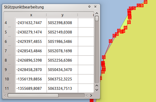
Stützpunktbearbeitungsbedienfeld mit ausgewählten Knoten
Objekte ausschneiden, kopieren und einfügen
Ausgewählte Objekte können ausgeschnitten, kopiert und an andere Ebenen im aktuellen QGIS-Projekt übergeben (eingefügt) werden, wenn sich der Ziellayer auch im Editiermodus befindet, indem Sie nach Auswahl des Ziellayers auf den Knopf Bearbeitungsstatus umschalten klicken.
Tipp
Polygone in Linien und umgekehrt transformieren mit copy/paste
Kopieren Sie ein Linienobjekt und fügen Sie ihn in ein Polygonlayer ein: QGIS fügt ihn in den Ziellayer dessen Begrenzung am nächsten der Geometrie des Linienobjekts entspricht. Dies ist ein einfacher Weg, um verschiedene Geometrien der selben Daten zu erzeugen.
Features can also be pasted to external applications as text. That is, the features are represented in CSV format, with the geometry data appearing in the OGC Well-Known Text (WKT) format. WKT and GeoJSON features from outside QGIS can also be pasted to a layer within QGIS.
Aber wann macht es Sinn, Objekte zum kopieren, auszuschneiden und einzufügen? Ein Beispiel ist, wenn Sie parallel an mehreren Layern arbeiten und Objekte zwischen den Layern hin- und herkopieren möchten. Ein Szenario könnte sein, dass Sie einen neuen Layer erstellen möchten, in dem aber nur einige Objekte aus einem bereits existierenden Layer verwendet werden sollen, wie etwa 5 Seen aus der Karte lakes.shp , die insgesamt aber tausende Seen enthält.
Als Beispiel werden wir einige Seen in einen neuen Layer kopieren:
Laden Sie den Layer, von dem Sie einige Objekte kopieren wollen (Quelle)
Laden oder erstellen Sie einen Layer, in den die kopierten Objekte eingefügt werden sollen (Ziel)
Schalten Sie für den Ziel Layer den Bearbeitungsstatus ein
Stellen Sie die Quelle aktiv, indem Sie es in der Legende anklicken
 Objekte über Fläche oder Einzelklick wählen um Objekte aus dessen Quelllayer zu wählen
Klicken Sie auf das Icon
Objekte kopierenStellen Sie das ‘Ziel’ aktiv, indem Sie es in der Legende anklicken
Klicken Sie auf das Icon
Objekte einfügenBeenden Sie den Bearbeitungsstatus für beide Layer und speichern Sie das Ergebnis ab
Was passiert, wenn der Quell- und Ziellayer ein unterschiedliches Schema enthält (Spaltennamen und -typen unterscheiden sich)? QGIS verwendet die Einträge, die gleich sind und ignoriert den Rest. Wenn es Ihnen egal ist, ob die Attribute korrekt übernommen werden, dann ist es egal, wie Sie die Spaltennamen und -typen der Attributtabelle erstellen. Wenn auch die Attributdaten korrekt übernommen werden sollen, dann stellen Sie sicher, dass auch die Spaltennamen und -typen beider Layer zueinander passen.
Bemerkung
Deckungsgleichheit eingefügter Objekte
Wenn Ihre Quell- und Ziellayer die gleiche Projektion verwenden dann haben die eingefügten Objekte die identische Geometrie wie der Quellayer. Wenn der Ziellayer jedoch eine andere Projektion hat dann kann QGIS nicht garantieren dass die Geometrie identisch ist. Dies ist einfach aus dem Grund so, dass sich kleine Rundungsfehler ergeben wenn zwischen Projektionen konvertiert wird.
Tipp
Zeichenketten Attribut in ein anderes kopieren
Wenn Sie eine neue Spalte in die Attributtabelle mit dem Typ ‘string’ erstellt haben und die Werte von einer anderen Attributspalte einfügen, die eine größere Länge als die Länge der Spaltengröße hat, wird diese auf den gleichen Betrag verlängert werden. Dies ist so, weil der GDAL Shapedatei Driver beginnend ab GDAL/OGR 1.10 String und Integer Fehler auto-erkennt und die Felder auf die benötigte Länge der eingefügten Daten anpasst.
Ausgewählte Objekte löschen
Wenn Sie ein gesamtes Objekt (Attribut und Geometrie) löschen wollen, können Sie das tun, indem Sie zunächst die Geometrie der Objekte über Fläche oder Einzelklick wählen auswählen. Die Auswahl kann auch über die Attributtabelle erfolgen. Sobald Sie die Auswahl festgelegt haben, drücken Sie :knd:`Entfernen` oder Rücktaste oder nutzen Sie Ausgewähltes löschen um Objekte zu löschen. Mehrfachauswahlen können ebenso auf einmal gelöscht werden.
Das Werkzeug Ausgewählte Objekte ausschneiden kann auch benutzt werden, um Objekte zu löschen. Die Objekte werden gelöscht aber zusätzlich noch im ‘spatial clipboard’ abgelegt. In diesem Fall könnte man dann den letzten Schritt, falls ein Fehler unterlaufen ist, wieder rückgängig machen, indem wir auf das Werkzeug Objekte einfügen drücken. Ausschneiden, kopieren und übergeben von Objekten funktioniert mit den gerade ausgewählten Objekten und können nach Bedarf kombiniert verwendet werden.
Änderungen speichern
Wenn ein Layer im Bearbeitungsmodus ist behält QGIS alle Änderungen im Speicher. Aus diesem Grund werden diese nicht umgehend der Datenquelle oder -platte übermittelt. Wenn Sie Bearbeitungen in dem aktuellen Layer speichern wollen aber mit dem Bearbeiten fortfahren wollen ohne den Bearbeitungsmodus verlassen zu wollen können Sie den Layeränderungen speichern Knopf klicken. Wenn Sie den Editiermodus mit Bearbeitungsstatus umschalten aussschalten wollen werden Sie ebenfalls gefragrt ob Sie Ihre Änderungen speichern oder verwerfen wollen.
Wenn die Änderungen nicht gespeichert werden können (z.B. weil die Festplatte voll ist oder Attribute Werte aufweisen, die außerhalb der Wertespanne liegen), bleiben die Änderungen erstmal im QGIS Arbeitsspeicher. Dies ermöglicht es, Änderungen vorzunehmen und dann nochmals die Daten zu speichern.
Tipp
Datenintegrität
Es ist immer gut ein Backup von Ihren Daten zu machen bevor Sie mit dem Bearbeiten starten. Während die Autoren von QGIS sich bemühen die Integrität Ihrer Daten zu bewahren bieten wir keine Garantie in dieser Hinsicht.
Mehrere Layer auf einmal speichern
Mit dieser neuen Funktion können Sie mehrere Layer digitalisieren. Wählen Sie  Layeränderungen speichern um alle Änderungen, die Sie in mehreren Layern gemacht haben, zu speichern. Sie haben auch die Möglichkeit
  Verwerfen für gewählte Layer zu benutzen so dass die Digitalisierung für alle selektierten Layer rückgängig gemacht werden kann. Wenn Sie das Bearbeiten der selektierten Layer beenden wollen kann man das einfach mit der Funktion
  Abbruch für gewählte Layer erreichen.
Die gleichen Funktionen sind für das Bearbeiten aller Layer des Projektes zugängig.
Tipp
Use transaction group to edit, save or rollback multiple layers changes at once
When working with layers from the same PostGreSQL database, activate the Automatically create transaction groups where possible option in Project ‣ Project Properties ‣ Data Sources to sync their behavior (enter or exit the edit mode, save or rollback changes at the same time).
Erweiterte Digitalisierung
| Icon | Funktion |
Icon | Funktion |
|---|---|---|---|
 |
Erweiterte Digitalsierungswerkzeuge einschalten |
 |
Spurverfolgung einschalten |
 |
Rückgängig |
 |
Wiederholen |
 |
Objekt(e) drehen |
 |
Objekt vereinfachen |
 |
Ring hinzufügen |
 |
Teil hinzufügen |
 |
Ring füllen |
||
 |
Ring löschen |
 |
Teil löschen |
 |
Linie versetzen |
 |
Objekte überarbeiten |
 |
Teile zerlegen |
 |
Objekte trennen |
 |
Attribute gewählter Objekte vereinen |
 |
Gewählte Objekte verschmelzen |
 |
Punktsymbole drehen |
 |
Offset Point Symbols |
Tabelle Erweiterte Digitalisierung: Werkzeugleiste Erweiterte Digitalisierung für Vektorlayer
Rückgängig und Wiederholen
The Undo and Redo tools allows you to undo or redo
vector editing operations. There is also a dockable widget, which shows all
operations in the undo/redo history (see Figure_edit_undo). This widget is not
displayed by default; it can be displayed by right-clicking on the toolbar and
activating the Undo/Redo Panel checkbox. The Undo/Redo capability
is however active, even if the widget is not displayed.
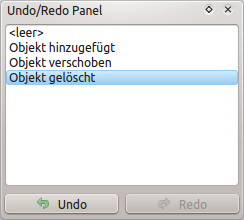
Rückgängig und Wiederholen von Digitalisierschritten
When Undo is hit or Ctrl+Z (or Cmd+Z) pressed, the state of all features and attributes are reverted to the state before the reverted operation happened. Changes other than normal vector editing operations (for example, changes done by a plugin) may or may not be reverted, depending on how the changes were performed.
Wenn Sie Rücknahme/Wiederholung verwenden wollen klicken Sie einfach auf eine Operation in der History; alle Objekte werden dann auf den Stand vor der ausgewählten Operation zurückgesetzt.
Objekt(e) drehen
Use Rotate Feature(s) to rotate one or multiple features
in the map canvas. Press the Rotate Feature(s) icon and then
click on the feature to rotate. Either click on the map to place the rotated feature or
enter an angle in the user input widget. If you want to rotate several features,
they shall be selected first.
If you enable the map tool with feature(s) selected, its (their) centroid appears and will be the rotation anchor point. If you want to move the anchor point, hold the Ctrl button and click on the map to place it.
Wenn Sie Shift vor dem Klick auf die Karte halten, wird die Drehung in 45 Grad Schritten erfolgen, was anschließend in dem Benutzerinterface-Widget bearbeitet werden kann.
To abort feature rotation, you need to click on Rotate
Feature(s) icon.
Objekt vereinfachen
The Simplify Feature tool allows you to reduce the
number of vertices of a feature, as long as the geometry remains valid. With the
tool you can also simplify many features at once or multi-part features.
First, click on the feature or drag a rectangle over the features. A dialog where you can define a tolerance in map units, layer units or pixels pops up and a colored and simplified copy of the feature(s), using the given tolerance, appears over them. QGIS calculates the amount of vertices that can be deleted while maintaining the geometry. The higher the tolerance is the more vertices can be deleted. When the expected geometry fits your needs just click the [OK] button. The tolerance you used will be saved when leaving a project or when leaving an edit session. So you can go back to the same tolerance the next time when simplifying a feature.
To abort feature simplification, you need to click on
Simplify Feature icon.
Bemerkung
Unlike the feature simplification option in Settings ‣
Options ‣ Rendering menu which simplifies the geometry just for rendering,
the Simplify Feature tool permanently modifies
feature’s geometry in data source.
Teil hinzufügen
You can Add Part to a selected feature generating a
multipoint, multiline or multipolygon feature. The new part must be digitized
outside the existing one which should be selected beforehand.
The Add Part can also be used to add a geometry to a geometryless
feature. First, select the feature in the attribute table and digitize the new
geometry with the Add Part tool.
Teil löschen
The Delete Part tool allows you to delete parts from
multifeatures (e.g., to delete polygons from a multi-polygon feature). This
tool works with all multi-part geometries: point, line and polygon. Furthermore,
it can be used to totally remove the geometric component of a feature.
To delete a part, simply click within the target part.
Ring hinzufügen
You can create ring polygons using the
Add Ring icon in the toolbar. This means that inside an existing area, it
is possible to digitize further polygons that will occur as a ‘hole’, so
only the area between the boundaries of the outer and inner polygons remains
as a ring polygon.
Ring füllen
You can use the Fill Ring function to add a ring to
a polygon and add a new feature to the layer at the same time. Using this tool,
you simply have to digitize a polygon within an existing one. Thus you need not
first use the Add Ring icon and then the
Add feature function anymore.
Ring löschen
Das Werkzeug Ring löschen ermöglicht es, Ringpolygone innerhalb eines existierenden Fläche zu löschen. Das Werkzeug funktioniert nur mit Polygon- und Multipolygonlayern. Es findet keine Veränderung statt, wenn es auf den äußeren Ring eines Polygons angewendet wird.
Objekte überarbeiten
You can reshape line and polygon features using the
Reshape Features tool on the toolbar. For lines, it replaces the line
part from the first to the last intersection with the original line.
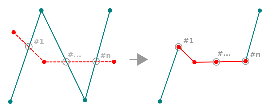
Reshape line
Tipp
Extend linestring geometries with reshape tool
Use the Reshape Features tool to extend existing linestring
geometries: snap to the first or last vertex of the line and draw a new one.
Validate and the feature’s geometry becomes the combination of the two lines.
For polygons, it will reshape the polygon’s boundary. For it to work, the reshape tool’s line must cross the polygon’s boundary at least twice. To draw the line, click on the map canvas to add vertexes. To finish it, just right-click. Like with the lines, only the segment between the first and the last intersections is considered. The reshape line’s segments that are inside the polygon will result in cropping it, where the ones outside the polygon will extend it.
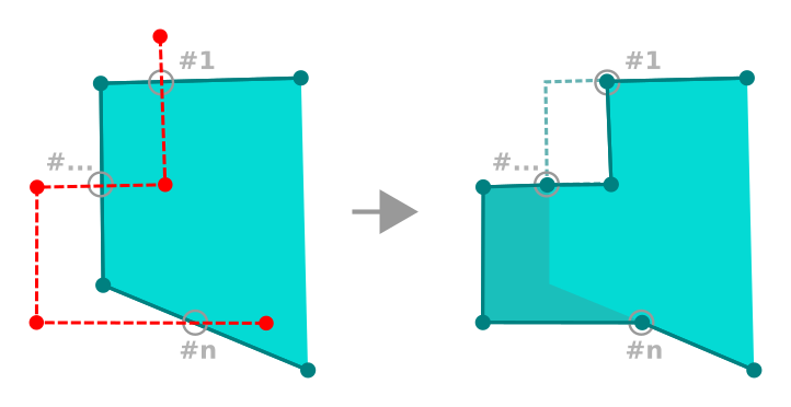
Reshape polygon
With polygons, reshaping can sometimes lead to unintended results. It is mainly useful to replace smaller parts of a polygon, not for major overhauls, and the reshape line is not allowed to cross several polygon rings, as this would generate an invalid polygon.
Bemerkung
Das Objekte überarbeiten Werkzeug kann die Startposition eines Polygonringes oder einer geschlossenen Linie verändern. Der Punkt, der zweimal abgebildet ist wird also nicht mehr der gleiche sein. Dies mag kein Problem für die meisten Anwendungen sein, sollte aber beachtet werden.
Linie versetzen
Das Linie versetzen Werkzeug erstellt parallele Linien von Linienlayern. Das Werkzeug kann auf den bearbeiteten Layer (die Geometrien werden verändert) und auch auf Hintergrundlayer (in diesem Fall erstellt es Kopien von Linien/ Ringen und fügt Sie dem bearbeiteten Layer hinzu) angewendet werden. Es ist auf diese Weise ideal geeignet Abstandslinienlayer zu erstellen. Der Benutzereingabe Dialog erscheint und zeigt den Versatz.
Um einen Versatz eines Linienlayers zu erstellen müssen Sie erst in den Bearbeitungsmodus gehen und das Offset Curve Werkzeug aktivieren. Klicken Sie dann auf ein Objekt, um es zu verschieben. Bewegen Sie die Maus und klicken Sie, wo Sie es haben wollen oder geben Sie die gewünschte Distanz in der Benutzereingabe ein. Ihre Änderungen können dann mit dem Layeränderungen speichern Werkzeug gespeichert werden.
Der QGIS Optionen Dialog (Digitalisierung Reiter dann Werkzeug zum Linien versetzen Abschnitt) ermöglicht es Ihnen einige Parameter wie Verbindungsstil,**Quadrantsegmente**, Eckengrenze zu konfigurieren.
Objekte trennen
You can split features using the Split Features
icon on the toolbar. Just draw a line across the feature you want to split.
Teile zerlegen
In QGIS ist es möglich die Teile eines Multi-Part Features zu zerlegen so dass die Anzahl der Teile sich erhöht. Zeichnen Sie einfach eine Linie über den Teil den Sie zerlegen wollen indem Sie dafür das Teile zerlegen Icon verwenden.
Tipp
Split a polyline feature in one-click
A single click on a snapped vertex of a line feature with the
Split Features or Split Parts tool is enough to have it
split into new features or parts.
Gewählte Objekte verschmelzen
The Merge Selected Features tool allows you to create
a new feature by merging existing ones: their geometries are merged to generate
a new one. If features don’t have common boundaries,
a multipolygon/multipolyline/multipoint feature is created.
First, select several features. Then press the Merge Selected
Features button. In the new dialog, you can select at the top of the dialog which value to
apply to each field of the new feature. That value can be:
- picked from the attributes of the initial features,
- an aggregation of the initial features attributes (Minimum, Maximum, Median, Sum, Count Concatenation... depending on the type of the field. see Statistical Summary Panel for the full list of functions),
- skipped, meaning that the field will be empty,
- or manually entered, at the bottom of the rows.
Attribute gewählter Objekte vereinen
The Merge Attributes of Selected Features tool
allows you to apply same attributes to features without merging their boundaries.
The dialog is the same as the Merge Selected Features tool’s except that
unlike that tool, selected objects are kept with their geometry while some of their
attributes are made identical.
Punktsymbole drehen
The Rotate Point Symbols allows you to change the rotation
of point symbols in the map canvas. First of all, you must apply to the symbol a
data-defined rotation: in the Layer Properties
‣ Style dialog, click the  Data-defined override widget
near the Rotation option of the highest level (preferably) of the symbol
layers and choose a field in the Field Type combobox. Values of this
field are hence used to rotate each feature’s symbol accordingly.
Data-defined override widget
near the Rotation option of the highest level (preferably) of the symbol
layers and choose a field in the Field Type combobox. Values of this
field are hence used to rotate each feature’s symbol accordingly.
Bemerkung
As a global option, setting the rotation field at the first level of the symbol applies it to all the underlying levels while setting it at a lower level will rotate only this symbol layer (unless you have a single symbol layer).
Punktsymbole drehen
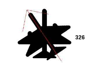
To change the rotation of a symbol, click on a point feature in the map canvas
with the Rotate Point Symbols and move the mouse around,
holding the left button pressed. A red arrow with the rotation value
will be visualized (see Figure_rotate_point). When you release the left mouse
button again, the symbol is defined with this new rotation and the rotation
field is updated in the layer’s attribute table.
Tipp
Wenn Sie zusätzlich die Strg-Taste gedrückt halten, findet die Drehung in 15 Grad Schritten statt.
Offset Point Symbols
The Offset Point Symbols allows you to interactively
change the rendered position of point symbols in the map canvas. This tool behaves
like the Rotate Point Symbols tool except that it
requires you to connect a field to the data-defined Offset (X,Y)
property of the symbol, field which will then be populated with the offset
coordinates while moving the symbol in the map canvas.
Bemerkung
The Offset Point Symbols tool doesn’t
move the point feature itself; you should use the Node Tool
or Move Feature tool for this purpose.
Warnung
Ensure to assign the same field to all symbol layers
If at least two layers of the symbol have different fields assigned to their data-defined property (e.g. rotation), the corresponding tool will consider that no field is assigned to the symbol property and won’t perform the action.
Automatische Verfolgung
Usually, when using capturing map tools (add feature, add part, add ring, reshape and split), you need to click each vertex of the feature.
Using the automatic tracing mode you can speed up the digitization process.
Enable the Tracing tool by pushing the icon or pressing
t key and snap to a vertex or segment of a
feature you want to trace along. Move the mouse over another vertex or segment
you’d like to snap and instead of an usual straight line, the digitizing rubber
band represents a path from the last point you snapped to the current position.
QGIS actually uses the underlying features topology to build the shortest path
between the two points. Click and QGIS places the intermediate vertices following
the path. You no longer need to manually place all the vertices during digitization.
Tracing requires snapping to be activated in traceable layers to build the path. You should also snap to an existing vertex or segment while digitizing and ensure that the two nodes are topologically connectable following existing features, otherwise QGIS is unable to connect them and thus traces a single straight line.
Bemerkung
Justieren Sie den Kartenmaßstab oder die Fangeinstellungen für eine optimale Verfolgung
Wenn zu viele Objekte in der Karte gezeigt werden, ist Verfolgung möglicherweise deaktiviert, um potentielle langsame Verfolgung und große Speicherzuschläge zu vermeiden. Nach dem hereinzoomen oder dem ausblenden einiger Layer, ist die Funktion wieder aktiviert.
Tipp
Quickly enable or disable automatic tracing by pressing t key
By pressing t key, tracing can be enabled/disabled anytime even while digitizing one feature, so it is possible to digitize some parts of the feature with tracing enabled and other parts with tracing disabled. Tools behave as usual when tracing is disabled.
Das erweiterte Digitalisierungsfenster
When capturing, reshaping, splitting new or existing geometries you also have the possibility to use the Advanced Digitizing panel. You can digitize lines exactly parallel or perpendicular to a particular angle or lock lines to specific angles. Furthermore, you can enter coordinates directly so that you can make a precise definition of your new geometry.
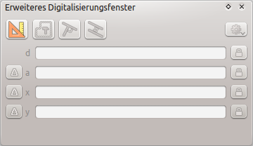
Das erweiterte Digitalisierungsfenster
Bemerkung
Die Werkzeuge sind nicht aktiviert, wenn die Kartenansicht geographische Koordinaten zeigt.
The Advanced Digitizing panel can be open either with a right-click on the
toolbar and choose Advanced Digitizing panel or in View ‣
Panels ‣ Advanced Digitizing Panel. Once the panel is visible, click the
enable advanced digitizing tool button to activate the Advanced
Digitizing tool.
Concepts
The aim of the Advanced Digitizing tool is to lock coordinates, lengths, and angles when moving the mouse during the digitalizing in the map canvas.
You can also create constraints with relative or absolute reference. Relative reference means that the next vertex constraints’ values will be relative to the previous vertex or segment.
Snapping Settings
Click the  button to set the Advanced Digitizing Tool snapping settings.
You can make the tool snap to common angles. The options are:
button to set the Advanced Digitizing Tool snapping settings.
You can make the tool snap to common angles. The options are:
- Do not snap to common angles
- Snap to 30º angles
- Snap to 45º angles
- Snap to 90º angles
You can also control the snapping to features. The options are:
- Do not snap to vertices or segments
- Snap according to project configuration
- Snap to all layers
Keyboard shortcuts
To speed up the use of Advanced Digitizing Panel, there are a couple of keyboard shorcuts available:
| Key | Simple | Ctrl + or Alt + | Shift + |
|---|---|---|---|
| d | Set distance | Lock distance | |
| a | Set angle | Lock angle | Toggle relative angle to last segment |
| x | Set x coordinate | Lock x coordinate | Toggle relative x to last vertex |
| y | Set y coordinate | Lock y coordinate | Toggle relative y to last vertex |
| c | Toggle construction mode | ||
| p | Toggle perpendicular and parallel modes | ||
Absolute reference digitizing
When drawing a new geometry from scratch, it is very useful to have the possibility to start digitizing vertexes at given coordinates.
For example, to add a new feature to a polygonal layer, click the
button. You can choose the X and Y coordinates where you want
to start editing the feature, then:
- Click the x text box (or use the x keyboard shortcuts).
- Type the X coordinate value you want and press Enter or click the
 button to their right to lock the mouse to the X axis on the map
canvas.
button to their right to lock the mouse to the X axis on the map
canvas. - Click the y text box (or use the y keyboard shortcuts).
- Type the Y coordinate value you want and press Enter or click the
button to their right to lock the mouse to the Y axis on the map
canvas.
Two blue dotted lines and a green cross identify the exact coordinates you entered. Start digitizing by clicking on the map canvas; the mouse position is locked at the green cross.
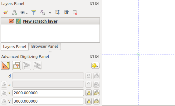
Start drawing at given coordinates
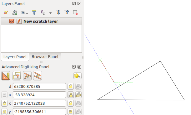
You can continue digitizing by free hand, adding a new pair of coordinates, or you can type the segment’s length (distance) and angle.
If you want to draw a segment of a given length, click the d
(distance) text box (keyboard shortcut d), type the distance value (in
map units) and press Enter or click the button on the right to
lock the mouse in the map canvas to the length of the segment.
In the map canvas, the clicked point is surrounded by a circle whose radius is
the value entered in the distance text box.
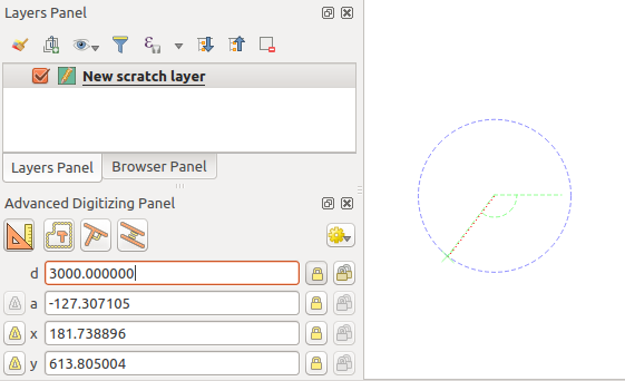
Fixed length segment
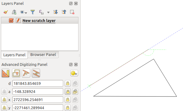
Finally, you can also choose the angle of the segment. As described before ,
click the a (angle) text box (keyboard shortcut a), type the
angle value (in degrees), and press Enter or click the buttons
on the right to lock it. In this way the segment will follow the desired angle:
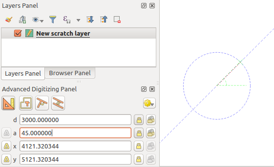
Fixed angle segment
Relative reference digitizing
Instead of using absolute values of angles or coordinates, you can also use values relative to the last digitized vertex or segment.
For angles, you can click the  button on the left of the a
text box (or press Shift + a) to toggle relative angles to the previous
segment. With that option on, angles are measured between the last segment
and the mouse pointer.
button on the left of the a
text box (or press Shift + a) to toggle relative angles to the previous
segment. With that option on, angles are measured between the last segment
and the mouse pointer.
For coordinates, click the buttons to the left of the x or
y text boxes (or press Shift + x or Shift + y) to
toggle relative coordinates to the previous vertex. With these options on,
coordinates measurement will consider the last vertex to be the x and y axes
origin.
Continuous lock
Both in absolute or relative reference digitizing, angle, distance, x and y
constraints can be locked continuously by clicking the  Continuous lock buttons. Using continuous lock allows you to
digitize several points or vertexes using the same constraints.
Continuous lock buttons. Using continuous lock allows you to
digitize several points or vertexes using the same constraints.
Parallel and perpendiculars line
All the tools described above can be combined with the  Perpendicular and
  Parallel tools. These two tools
allow drawing segments perfectly perpendicular or parallel to another segment.
Parallel tools. These two tools
allow drawing segments perfectly perpendicular or parallel to another segment.
To draw a perpendicular segment, during the editing click the
Perpendicular icon (keyboard shortcut p) to
activate it. Before drawing the perpendicular line,
click on the segment of an existing feature that you want to be perpendicular
to (the line of the existing feature will be colored in light orange); you
should see a blue dotted line where your feature will be snapped:
Perpendicular digitizing
To draw a parallel feature, the steps are the same: click on the
Parallel icon (keyboard shortcut p twice), click on
the segment you want to use as reference and start drawing your feature:
Parallel digitizing
These two tools just find the right angle of the perpendicular and parallel angle and lock this parameter during your editing.
Construction mode
You can enable and disable construction mode by clicking on the
 Construction icon or with the c keyboard
shortcut. While in construction mode, clicking the map canvas won’t add new
vertexes, but will capture the clicks’ positions so that you can use them as
reference points to then lock distance, angle or x and y relative values.
Construction icon or with the c keyboard
shortcut. While in construction mode, clicking the map canvas won’t add new
vertexes, but will capture the clicks’ positions so that you can use them as
reference points to then lock distance, angle or x and y relative values.
As an example, the construction mode can be used to draw some point at an exact distance from an existing point.
With an existing point in the map canvas and the snapping mode correctly
activated, you can easily draw other points at given distances and angles from
it. In addition to the button, you have to activate also the
construction mode by clicking the Construction
icon or with the c keyboard shortcut.
Click next to the point from which you want to calculate the distance and click on the d box (d shortcut) type the desired distance and press Enter to lock the mouse position in the map canvas:
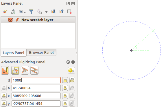
Distance from point
Before adding the new point, press c to exit the construction mode. Now, you can click on the map canvas, and the point will be placed at the distance entered.
You can also use the angle constraint to, for example, create another point at
the same distance of the original one, but at a particular angle from the newly
added point. Click the Construction icon or with the
c keyboard shortcut to enter construction mode. Click the recently added
point, and then the other one to set a direction segment. Then, click on the
d text box (d shortcut) type the desired distance and press
Enter. Click the a text box (a shortcut) type the
angle you want and press Enter. The mouse position will be locked both in
distance and angle.
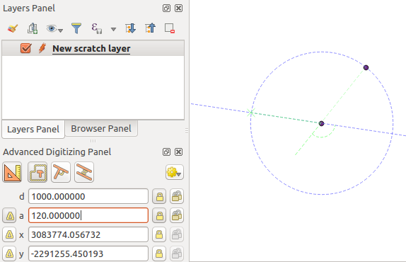
Distance and angle from points
Before adding the new point, press c to exit the construction mode. Now, you can click on the map canvas, and the point will be placed at the distance and angle entered. Repeating the process, several points can be added.
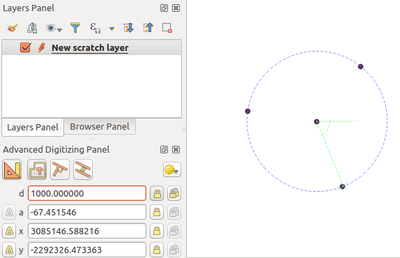
Points at given distance and angle