Vector geometry
Add geometry attributes
Computes geometric properties of the features in a vector layer and includes them in the output layer.
It generates a new vector layer with the same content as the input one, but with additional attributes, containing geometric measurements based on a selected CRS.
The attributes added to the table depend on the geometry type and dimension of the input layer:
for point layers: X (
xcoord), Y (ycoord), Z (zcoord) coordinates and/or M value (mvalue)for line layers:
lengthand, for the LineString and CompoundCurve geometry types, the featuresinuosityand straight distance (straightdis)for polygon layers:
perimeterandarea
Default menu:
Parameters
Label |
Name |
Type |
Description |
|---|---|---|---|
Input layer |
|
[vector: any] |
Input vector layer |
Calculate using |
|
[enumeration] Default: 0 |
Calculation parameters to use for the geometric properties. One of:
|
Added geom info |
|
[same as input] Default: |
Specify the output (input copy with geometry) layer One of:
The file encoding can also be changed here. |
Outputs
Label |
Name |
Type |
Description |
|---|---|---|---|
Added geom info |
|
[same as input] |
Copy of the input vector layer with the addition of the geometry fields |
Aggregate
Takes a vector or table layer and creates a new layer by aggregating
features based on a group by expression.
Features for which group by expression returns the same value are
grouped together.
It is possible to group all source features together using constant
value in group by parameter, example: NULL.
It is also possible to group features by multiple fields using Array function, example: Array(“Field1”, “Field2”).
Geometries (if present) are combined into one multipart geometry for each group. Output attributes are computed depending on each given aggregate definition.
This algorithm allows to use the default aggregates functions of the QGIS Expression engine.
See also
Parameters
Label |
Name |
Type |
Description |
|---|---|---|---|
Input layer |
|
[vector: any] |
Input vector layer |
Group by expression |
|
[tablefield: any] Default: ‘NULL’ |
Choose the grouping field. If NULL all features will be grouped. |
Aggregates |
|
[list] |
List of output layer field definitions. Example of a field definition: {‘aggregate’: ‘sum’, ‘delimiter’: ‘,’, ‘input’: ‘ $area’, ‘length’: 10, ‘name’: ‘totarea’, ‘precision’: 0, ‘type’: 6} By default, the list contains all the fields of the input layer. In the GUI, you can edit these fields and their definitions, and you can also:
For each of the fields you’d like to retrieve information from, you need to define the following:
|
Load fields from layer |
GUI only |
[vector: any] |
You can load fields from another layer and use them for the aggregation |
Aggregated |
|
[same as input] Default: |
Specify the output (aggregate) layer One of:
The file encoding can also be changed here. |


Outputs
Label |
Name |
Type |
Description |
|---|---|---|---|
Aggregated |
|
[same as input] |
Multigeometry vector layer with the aggregated values |
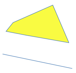
Boundary
Returns the closure of the combinatorial boundary of the input geometries (i.e. the topological boundary of the geometry).
Only for polygon and line layers.
For polygon geometries , the boundary consists of all the lines making up the rings of the polygon.
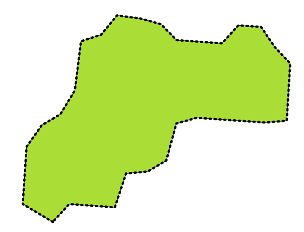
Boundaries (black dashed line) of the source polygon layer
For lines geometries, the boundaries are their end points.
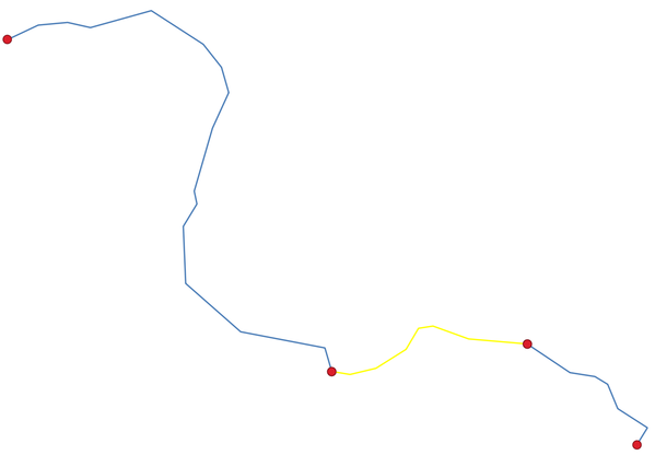
Boundary layer (red points) for lines. In yellow a selected feature.
Parameters
Label |
Name |
Type |
Description |
|---|---|---|---|
Input layer |
|
[vector: line, polygon] |
Input line or polygon vector layer |
Boundary |
|
[vector: point, line] Default: |
Specify the output (boundary) layer. One of:
The file encoding can also be changed here. |
Outputs
Label |
Name |
Type |
Description |
|---|---|---|---|
Boundary |
|
[vector: point, line] |
Boundaries from the input layer (point for line, and line for polygon) |
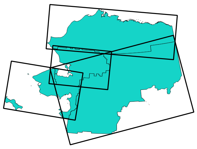
Bounding boxes
Calculates the bounding box (envelope) of each feature in an input layer. Polygon and line geometries are supported.
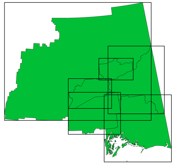
Black lines represent the bounding boxes of each polygon feature
 Allows
features in-place modification
Allows
features in-place modification
See also
Parameters
Label |
Name |
Type |
Description |
|---|---|---|---|
Input layer |
|
[vector: line, polygon] |
Input line or polygon vector layer |
Bounds |
|
[vector: polygon] Default: |
Specify the output (bounding box) layer. One of:
The file encoding can also be changed here. |
Outputs
Label |
Name |
Type |
Description |
|---|---|---|---|
Bounds |
|
[vector: polygon] |
Bounding boxes of input layer |
Buffer
Computes a buffer area for all the features in an input layer, using a fixed distance.
It is possible to use a negative distance for polygon input layers. In this case the buffer will result in a smaller polygon (setback).
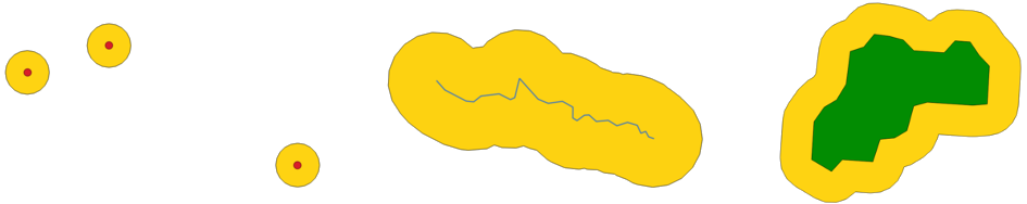
Buffer (in yellow) of points, line and polygon
Allows
features in-place modification
Default menu:
See also
Variable distance buffer (Graphical Modeler only), Multi-ring buffer (constant distance), Variable width buffer (by M value)
Parameters
Label |
Name |
Type |
Description |
|---|---|---|---|
Input layer |
|
[vector: any] |
Input vector layer |
Distance |
|
[number Default: 10.0 |
Buffer distance (from the boundary of each feature). You can use the Data Defined button on the right to choose a field from which the radius will be calculated. This way you can have different radius for each feature (see Variable distance buffer (Graphical Modeler only)). |
Segments |
|
[number] Default: 5 |
Controls the number of line segments to use to approximate a quarter circle when creating rounded offsets. |
End cap style |
|
[enumeration] Default: 0 |
Controls how line endings are handled in the buffer. One of:
Round, flat and square cap styles¶ |
Join style |
|
[enumeration] Default: 0 |
Specifies whether round, miter or beveled joins should be used when offsetting corners in a line. Options are:
|
Miter limit |
|
[number] Default: 2.0 |
Controls the maximum distance from the offset curve to use when creating a mitered join (only applicable for miter join styles). Minimum: 1. |
Dissolve result |
|
[boolean] Default: False |
Dissolve the final buffer. If 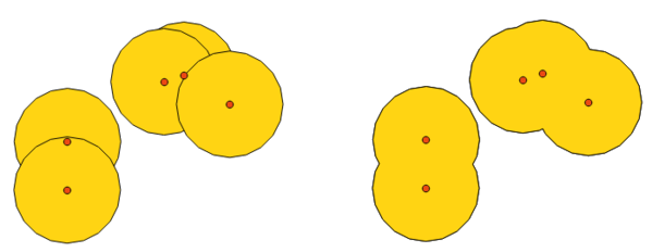
Standard and dissolved buffer¶ |
Buffered |
|
[vector: polygon] Default: |
Specify the output (buffer) layer. One of:
The file encoding can also be changed here. |

Outputs
Label |
Name |
Type |
Description |
|---|---|---|---|
Buffered |
|
[vector: polygon] |
Output (buffer) polygon layer |
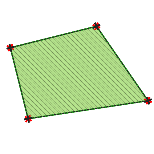
Centroids
Creates a new point layer, with points representing the centroids of the geometries of the input layer.
The centroid is a single point representing the barycenter (of all parts) of the feature, so it can be outside the feature borders. But can also be a point on each part of the feature.
The attributes of the points in the output layer are the same as for the original features.
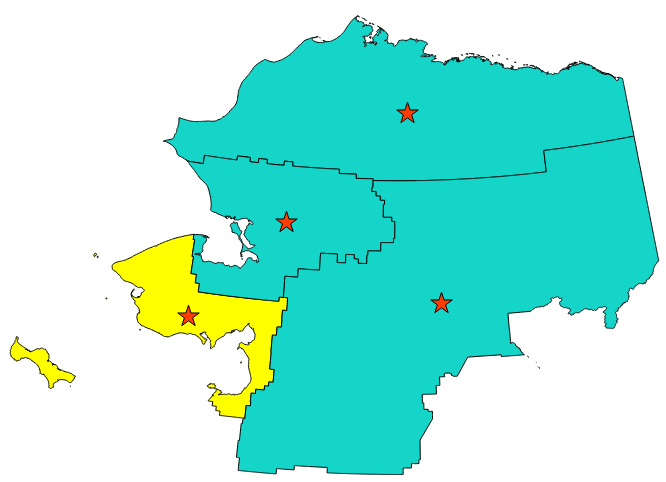
The red stars represent the centroids of the features of the input layer.
Allows
features in-place modification
Default menu:
See also
Parameters
Label |
Name |
Type |
Description |
|---|---|---|---|
Input layer |
|
[vector: any] |
Input vector layer |
Create centroid for each part |
|
[boolean Default: False |
If True (checked), a centroid will be created for each part of the geometry |
Centroids |
|
[vector: point] Default: |
Specify the output (centroid) layer. One of:
The file encoding can also be changed here. |
Outputs
Label |
Name |
Type |
Description |
|---|---|---|---|
Centroids |
|
[vector: point] |
Output point vector layer (centroids) |
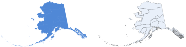
Check validity
Performs a validity check on the geometries of a vector layer.
The geometries are classified in three groups (valid, invalid and error) and for each group, a vector layer with its features is generated:
The Valid output layer contains only the valid features (without topological errors).
The Invalid output layer contains all the invalid features found by the algorithm.
The Error output layer is a point layer that points to where the invalid features were found.
The attribute tables of the generated layers will contain some additional information (“message” for the error layer, “FID” and “_errors” for the invalid layer and only “FID” for the valid layer):
The attribute table of each generated vector layer will contain some additional information (number of errors found and types of error):
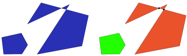
Left: the input layer. Right: the valid layer (green), the invalid layer (orange)
Default menu:
See also
Fix geometries and the core plugin Geometry Checker Plugin
Parameters
Label |
Name |
Type |
Description |
|---|---|---|---|
Input layer |
|
[vector: any] |
Input vector layer |
Method |
|
[enumeration] Default: 2 |
Method to use to check validity. Options:
|
Ignore ring self intersection |
|
[boolean] Default: False |
Ignore self intersecting rings when checking for validity. |
Valid output |
|
[same as input] Default: |
Specify the vector layer to contain a copy of the valid features of the source layer. One of:
The file encoding can also be changed here. |
Invalid output |
|
[same as input] Default: |
Vector layer containing copy of the invalid features of
the source layer with the field
The file encoding can also be changed here. |
Error output |
|
[vector: point] Default: |
Point layer of the exact position of the validity
problems detected with the
The file encoding can also be changed here. |
Outputs
Label |
Name |
Type |
Description |
|---|---|---|---|
Count of errors |
|
[number] |
The number of geometries that caused errors. |
Error output |
|
[vector: point] |
Point layer of the exact position of the validity
problems detected with the |
Count of invalid features |
|
[number] |
The number of invalid geometries. |
Invalid output |
|
[same as input] |
Vector layer containing copy of the invalid features of
the source layer with the field |
Count of valid features |
|
[number] |
The number of valid geometries. |
Valid output |
|
[same as input] |
Vector layer containing a copy of the valid features of the source layer. |
Types of error messages and their meanings
Error message |
Explanation |
Example |
|---|---|---|
Repeated point |
This error happens when a given vertex is repeated. |
|
Ring self-intersection |
This error happens when a geometry touches itself and generates a ring. |
|
Self-intersection |
This error happens when a geometry touches itself. |
|
Topology validation error |
||
Hole lies outside shell |
||
Holes are nested |
||
Interior is disconnected |
||
Nested shells |
This error happens when a polygon geometry is on top of another polygon geometry. |
|
Duplicate rings |
This error happens when two rings (exterior or interior) of a polygon geometry are identical |
|
Too few points in geometry component |
||
Invalid coordinate |
For a point geometry, this error happens when the geometry does not have a proper coordinate pair. The coordinate pair does not contain a latitude value and a longitude value in that order. |
|
Ring is not closed |
Error message |
Explanation |
Example |
|---|---|---|
Segment %1 of ring %2 of polygon %3 intersects segment %4 of ring %5 of polygon %6 at %7 |
||
Ring %1 with less than four points |
||
Ring %1 not closed |
||
Line %1 with less than two points |
||
Line %1 contains %n duplicate node(s) at %2 |
This error happens when consecutive points on a line have the same coordinates. |
|
Segments %1 and %2 of line %3 intersect at %4 |
This error happens when a line self intersects (two segments of the line intersect each other). |
|
Ring self-intersection |
This error happens when an outer or inner (island) ring / boundary of a polygon geometry intersects itself. |
|
Ring %1 of polygon %2 not in exterior ring |
||
Polygon %1 lies inside polygon %2 |
This error happens when a part of a MultiPolygon geometry is inside a hole of a MultiPolygon geometry. |
|
Collect geometries
Takes a vector layer and collects its geometries into new multipart geometries.
One or more attributes can be specified to collect only geometries belonging to the same class (having the same value for the specified attributes), alternatively all geometries can be collected.
All output geometries will be converted to multi geometries, even those with just a single part. This algorithm does not dissolve overlapping geometries - they will be collected together without modifying the shape of each geometry part.
See the ‘Promote to multipart’ or ‘Aggregate’ algorithms for alternative options.
Default menu:
See also
Parameters
Label |
Name |
Type |
Description |
|---|---|---|---|
Input layer |
|
[vector: any] |
Input vector layer |
Unique ID fields |
|
[tablefield: any] [list] |
Choose one or more attributes to collect the geometries |
Collected |
|
[same as input] |
Vector layer with collected geometries |
Outputs
Label |
Name |
Type |
Description |
|---|---|---|---|
Collected |
|
[same as input] Default: |
Specify the output vector layer for the collected geometries. One of:
The file encoding can also be changed here. |
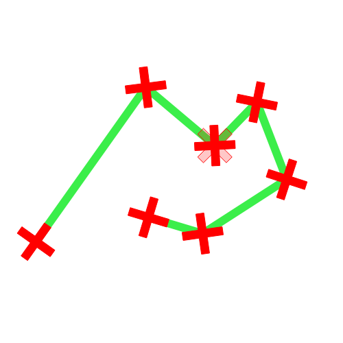
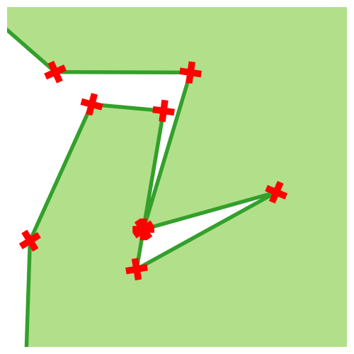
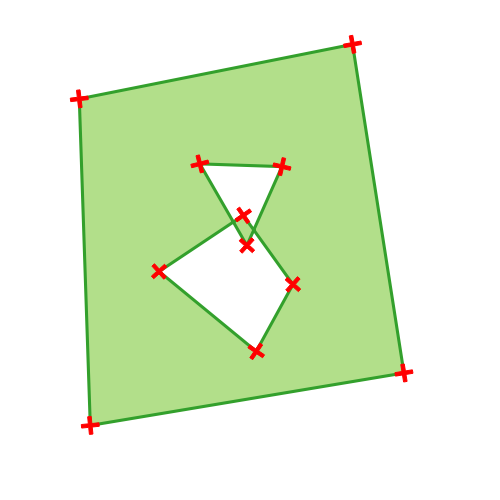
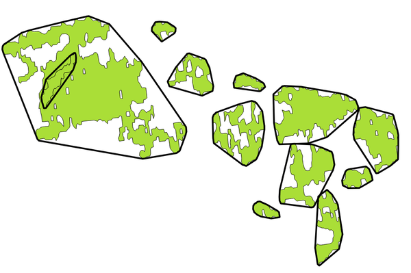
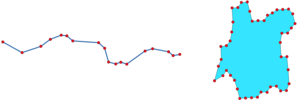
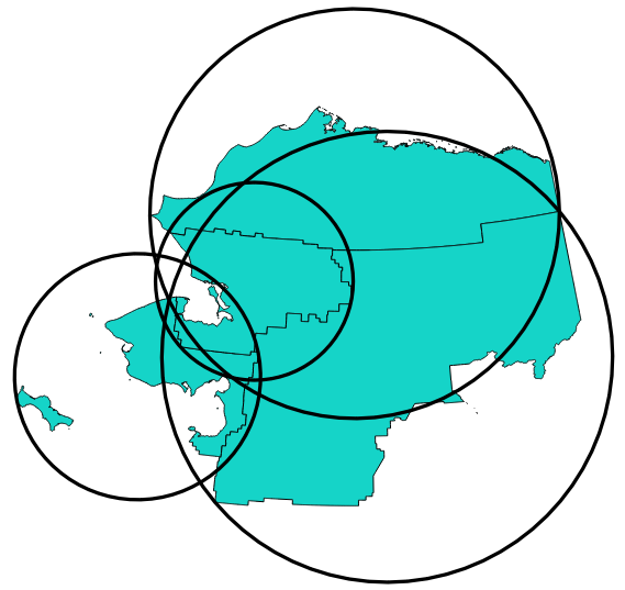
Concave hull (alpha shapes)
Computes the concave hull of the features in an input point layer.
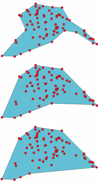
Concave hulls with different thresholds (0.3, 0.6, 0.9)
See also
Parameters
Label |
Name |
Type |
Description |
|---|---|---|---|
Input point layer |
|
[vector: point] |
Input point vector layer |
Threshold |
|
[number] Default: 0.3 |
Number from 0 (maximum concave hull) to 1 (convex hull). |
Allow holes |
|
[boolean] Default: True |
Choose whether to allow holes in the final concave hull |
Split multipart geometry into singlepart geometries |
|
[boolean] Default: True |
Check if you want to have singlepart geometries instead of multipart ones. |
Concave hull |
|
[vector: polygon] Default: |
Specify the output vector layer. One of:
The file encoding can also be changed here. |
Outputs
Label |
Name |
Type |
Description |
|---|---|---|---|
Concave hull |
|
[vector: polygon] |
The output vector layer |
Concave hull (k-nearest neighbor)
This algorithm generates a concave hull polygon from a set of points. If the input layer is a line or polygon layer, it will use the vertices.
The number of neighbors to consider determines the concaveness of the output polygon. A lower number will result in a concave hull that follows the points very closely, while a higher number will have a smoother shape. The minimum number of neighbor points to consider is 3. A value equal to or greater than the number of points will result in a convex hull.
If a field is selected, the algorithm will group the features in the input layer using unique values in that field and generate individual polygons in the output layer for each group.
See also
Parameters
Label |
Name |
Type |
Description |
|---|---|---|---|
Input layer |
|
[vector: any] |
Input vector layer |
Number of neighboring points to consider (a lower number is more concave, a higher number is smoother) |
|
[number] Default: 3 |
Determines the concaveness of the output polygon. A small number will result in a concave hull that follows the points very closely, while a high number will make the polygon look more like the convex hull (if the number is equal to or larger than the number of features, the result will be the convex hull). Minimum value: 3. |
Field Optional |
|
[tablefield: any] Default: None |
If specified, one concave hull polygon is generated for each unique value of the field (by selecting features using this value). |
Concave hull |
|
[vector: polygon] Default: |
Specify the output vector layer. One of:
The file encoding can also be changed here. |
Outputs
Label |
Name |
Type |
Description |
|---|---|---|---|
Concave hull |
|
[vector: polygon] |
The output vector layer |
Convert geometry type
Generates a new layer based on an existing one, with a different type of geometry.
Not all conversions are possible. For instance, a line layer can be converted to a point layer, but a point layer cannot be converted to a line layer.
See also
Parameters
Label |
Name |
Type |
Description |
|---|---|---|---|
Input layer |
|
[vector: any] |
Input vector layer |
New geometry type |
|
[enumeration] Default: 0 |
Geometry type to apply to the output features. One of:
Note The available conversion types depend on the input layer and the conversion chosen: e.g. it is not possible to convert a point to a line. |
Converted |
|
[vector: any] Default: |
Specify the output vector layer. One of:
The file encoding can also be changed here. |
Outputs
Label |
Name |
Type |
Description |
|---|---|---|---|
Converted |
|
[vector: any] |
Output vector layer - the type depends on the parameters |
Convex hull
Calculates the convex hull for each feature in an input layer.
See the ‘Minimum bounding geometry’ algorithm for a convex hull calculation which covers the whole layer or grouped subsets of features.
Black lines identify the convex hull for each layer feature
Allows
features in-place modification
Default menu:
Parameters
Label |
Name |
Type |
Description |
|---|---|---|---|
Input layer |
|
[vector: any] |
Input vector layer |
Convex hull |
|
[vector: polygon] Default: |
Specify the output vector layer. One of:
The file encoding can also be changed here. |
Outputs
Label |
Name |
Type |
Description |
|---|---|---|---|
Convex hull |
|
[vector: polygon] |
The output (convex hull) vector layer |
Create layer from extent
Creates a new vector layer that contains a single feature with geometry matching the extent of the input layer.
It can be used in models to convert a literal extent (xmin,
xmax, ymin, ymax format) into a layer which can be used
for other algorithms which require a layer based input.
Parameters
Label |
Name |
Type |
Description |
|---|---|---|---|
Extent (xmin, xmax, ymin, ymax) |
|
[extent] |
Input extent |
Extent |
|
[vector: polygon] Default: |
Specify the output vector layer. One of:
The file encoding can also be changed here. |
Outputs
Label |
Name |
Type |
Description |
|---|---|---|---|
Extent |
|
[vector: polygon] |
The output (extent) vector layer |
Create wedge buffers
Creates wedge shaped buffers from input points.
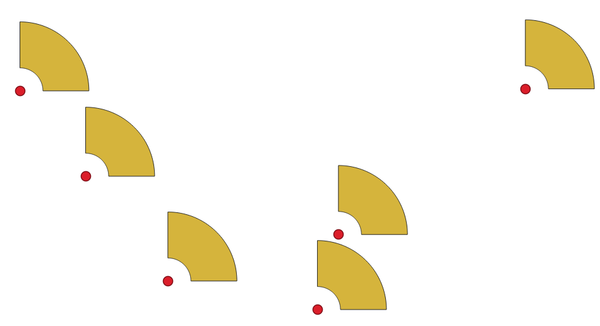
Wedge buffers
The native output from this algorithm are CurvePolygon geometries, but these may be automatically segmentized to Polygons depending on the output format.
Parameters
Label |
Name |
Type |
Description |
|---|---|---|---|
Input layer |
|
[vector: point] |
Input point vector layer |
Azimuth (degrees from North) |
|
[number Default: 0.0 |
Angle (in degrees) as the middle value of the wedge |
Wedge width (in degrees) |
|
[number Default: 45.0 |
Width (in degrees) of the buffer. The wedge will extend to half of the angular width either side of the azimuth direction. 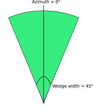
Azimuth and width values of the wedge buffer¶ |
Outer radius |
|
[number Default: 1.0 |
The outer size (length) of the wedge: the size is meant from the source point to the edge of the wedge shape. |
Inner radius Optional |
|
[number Default: 0.0 |
Inner radius value. If 0 the wedge will begin from the source point. |
Buffers |
|
[vector: polygon] Default: |
Specify the output vector layer. One of:
The file encoding can also be changed here. |
Outputs
Label |
Name |
Type |
Description |
|---|---|---|---|
Buffers |
|
[vector: polygon] |
The output (wedge buffer) vector layer |
Delaunay triangulation
Creates a polygon layer with the Delaunay triangulation corresponding to the input point layer.
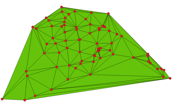
Delaunay triangulation on points
Default menu:
Parameters
Label |
Name |
Type |
Description |
|---|---|---|---|
Input layer |
|
[vector: point] |
Input point vector layer |
Delaunay triangulation |
|
[vector: polygon] Default: |
Specify the output vector layer. One of:
The file encoding can also be changed here. |
Outputs
Label |
Name |
Type |
Description |
|---|---|---|---|
Delaunay triangulation |
|
[vector: polygon] |
The output (Delaunay triangulation) vector layer |
Before and after the cleaning
Parameters
Label |
Name |
Type |
Description |
|---|---|---|---|
Input layer |
|
[vector: polygon] |
Input polygon vector layer |
Remove holes with area less than Optional |
|
[number Default: 0.0 |
Only holes with an area less than this threshold will be
deleted.
If |
Cleaned |
|
[same as input] Default: |
Specify the output vector layer. One of:
The file encoding can also be changed here. |
Outputs
Label |
Name |
Type |
Description |
|---|---|---|---|
Cleaned |
|
[same as input] |
The output (cleaned) vector layer |
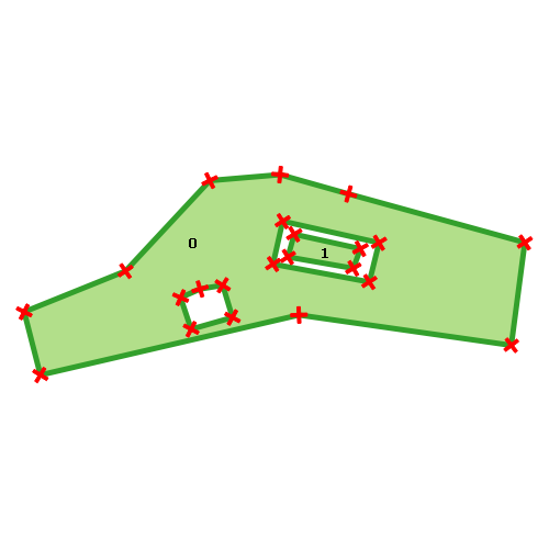
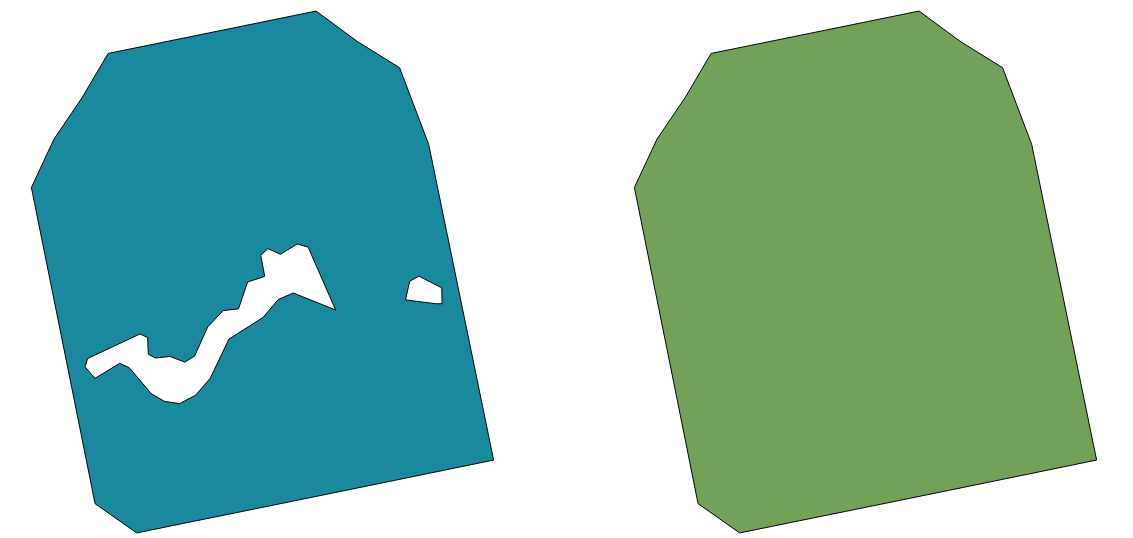
Delete holes
Takes a polygon layer and removes holes in polygons. It creates a new vector layer in which polygons with holes have been replaced by polygons with only their external ring. Attributes are not modified.
An optional minimum area parameter allows removing only holes which
are smaller than a specified area threshold. Leaving this parameter at
0.0 results in all holes being removed.
Before and after the cleaning
Allows
features in-place modification
Parameters
Label |
Name |
Type |
Description |
|---|---|---|---|
Input layer |
|
[vector: polygon] |
Input polygon vector layer |
Remove holes with area less than Optional |
|
[number Default: 0.0 |
Only holes with an area less than this threshold will be
deleted.
With a value of |
Cleaned |
|
[same as input] Default: |
Specify the output vector layer. One of:
The file encoding can also be changed here. |
Outputs
Label |
Name |
Type |
Description |
|---|---|---|---|
Cleaned |
|
[same as input] |
The output (cleaned) vector layer |
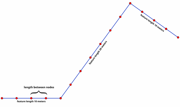
Densify by count
Takes a polygon or line layer and generates a new one in which the geometries have a larger number of vertices than the original one.
If the geometries have Z or M values present then these will be linearly interpolated at the added vertices.
The number of new vertices to add to each segment is specified as an input parameter.
Red points show the vertices before and after the densify
Allows
features in-place modification
Default menu:
See also
Parameters
Label |
Name |
Type |
Description |
|---|---|---|---|
Input layer |
|
[vector: line, polygon] |
Input line or polygon vector layer |
Vertices to add |
|
[number] Default: 1 |
Number of vertices to add to each segment |
Densified |
|
[same as input] Default: |
Specify the output vector layer. One of:
The file encoding can also be changed here. |
Outputs
Label |
Name |
Type |
Description |
|---|---|---|---|
Densified |
|
[same as input] |
The output (densified) vector layer |
Densify by interval
Takes a polygon or line layer and generates a new one in which the geometries have a larger number of vertices than the original one.
The geometries are densified by adding regularly placed extra vertices inside each segment so that the maximum distance between any two vertices does not exceed the specified distance.
If the geometries have Z or M values present then these will be linearly interpolated at the added vertices.
Example
Specifying a distance of 3 would cause the segment
[0 0] -> [10 0] to be converted to
[0 0] -> [2.5 0] -> [5 0] -> [7.5 0] -> [10 0],
since 3 extra vertices are required on the segment and spacing these
at 2.5 increments allows them to be evenly spaced over the segment.
Densify geometry at a given interval
Allows
features in-place modification
See also
Parameters
Label |
Name |
Type |
Description |
|---|---|---|---|
Input layer |
|
[vector: line, polygon] |
Input line or polygon vector layer |
Interval between vertices to add |
|
[number Default: 1.0 |
Maximum distance between two consecutive vertices |
Densified |
|
[same as input] Default: |
Specify the output vector layer. One of:
The file encoding can also be changed here. |
Outputs
Label |
Name |
Type |
Description |
|---|---|---|---|
Densified |
|
[same as input] |
The output (densified) vector layer |
Dissolve
Takes a vector layer and combines its features into new features. One or more attributes can be specified to dissolve features belonging to the same class (having the same value for the specified attributes), alternatively all features can be dissolved to a single feature.
All output geometries will be converted to multi geometries. In case the input is a polygon layer, common boundaries of adjacent polygons being dissolved will get erased.
The resulting attribute table will have the same fields as the input layer. The values in the output layer’s fields are the ones of the first input feature that happens to be processed.
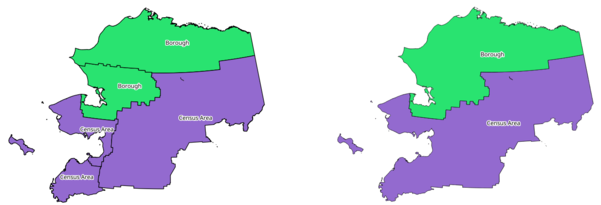
Dissolve the polygon layer on a common attribute
Default menu:
See also
Parameters
Label |
Name |
Type |
Description |
|---|---|---|---|
Input layer |
|
[vector: any] |
Input vector layer |
Dissolve field(s) Optional |
|
[tablefield: any] [list] Default: [] |
Features having the same value for the selected field(s) will be replaced with a single one and their geometries are merged. If no field is provided then all the features are dissolved, resulting in a single (multipart) feature. |
*Dissolved |
|
[same as input] Default: |
Specify the output vector layer. One of:
The file encoding can also be changed here. |
Outputs
Label |
Name |
Type |
Description |
|---|---|---|---|
Dissolved |
|
[same as input] |
The output vector layer with dissolved geometries |
Drape (set Z value from raster)
Uses values sampled from a band within a raster layer to set the Z value for every overlapping vertex in the feature geometry. The raster values can optionally be scaled by a preset amount.
If Z values already exist in the layer, they will be overwritten with the new value. If no Z values exist, the geometry will be upgraded to include the Z dimension.
See also
Parameters
Label |
Name |
Type |
Description |
|---|---|---|---|
Input layer |
|
[vector: any] |
Input vector layer |
Raster layer |
|
[raster] |
Raster layer with Z values |
Band number |
|
[raster band] Default: 1 |
The raster band to take the Z values from |
Value for nodata or non-intersecting vertices |
|
[number Default: 0 |
Value to use in case the vertex does not intersect (a valid pixel of) the raster |
Scale factor |
|
[number Default: 1.0 |
Scaling value: the band values are multiplied by this value. |
Updated |
|
[same as input] Default: |
Specify the output vector layer (with Z values from the raster layer). One of:
The file encoding can also be changed here. |
Outputs
Label |
Name |
Type |
Description |
|---|---|---|---|
Updated |
|
[same as input] |
The output vector layer with Z values from the raster layer |
Label |
Name |
Type |
Description |
|---|---|---|---|
Input layer |
|
[vector: any] |
Input vector layer with M or Z values |
Drop M Values |
|
[boolean] Default: False |
Removes the M values from the geometries |
Drop Z Values |
|
[boolean] Default: False |
Removes the Z values from the geometries |
Z/M Dropped |
|
[same as input] Default: |
Specify the output vector layer. One of:
The file encoding can also be changed here. |
Outputs
Label |
Name |
Type |
Description |
|---|---|---|---|
Z/M Dropped |
|
[same as input] |
The output vector layer (identical to the input layer, except that the M and/or Z dimensions have been removed from the geometries). |
Drop M/Z values
Removes M (measure) or Z (altitude) values from input geometries.
See also
Parameters
Label |
Name |
Type |
Description |
|---|---|---|---|
Input layer |
|
[vector: any] |
Input vector layer with M or Z values |
Drop M Values |
|
[boolean] Default: False |
Removes the M values from the geometries |
Drop Z Values |
|
[boolean] Default: False |
Removes the Z values from the geometries |
Z/M Dropped |
|
[same as input] Default: |
Specify the output vector layer. One of:
The file encoding can also be changed here. |
Outputs
Label |
Name |
Type |
Description |
|---|---|---|---|
Z/M Dropped |
|
[same as input] |
The output vector layer (identical to the input layer, except that the M and/or Z dimensions have been removed from the geometries). |
Eliminate selected polygons
Combines selected polygons of the input layer with certain adjacent polygons by erasing their common boundary. The adjacent polygon can be either the one with the largest or smallest area or the one sharing the largest common boundary with the polygon to be eliminated.
Eliminate is normally used to get rid of sliver polygons, i.e. tiny polygons that are a result of polygon intersection processes where boundaries of the inputs are similar but not identical.
Default menu:
See also
Parameters
Label |
Name |
Type |
Description |
|---|---|---|---|
Input layer |
|
[vector: polygon] |
Input polygon vector layer |
Merge selection with the neighboring polygon with the |
|
[enumeration] Default: None |
Choose the parameter to use in order to get rid of the selected polygons:
|
Eliminated |
|
[vector: polygon] Default: |
Specify the output vector layer. One of:
The file encoding can also be changed here. |
Outputs
Label |
Name |
Type |
Description |
|---|---|---|---|
Eliminated |
|
[vector: polygon] |
The output polygon vector layer. |
Explode lines
Takes a lines layer and creates a new one in which each line layer is replaced by a set of lines representing the segments in the original line.
Each line in the resulting layer contains only a start and an end point, with no intermediate vertices between them.
The original line layer and the exploded one
Allows
features in-place modification
See also
Parameters
Label |
Name |
Type |
Description |
|---|---|---|---|
Input layer |
|
[vector: line] |
Input line vector layer |
Exploded |
|
[vector: line] Default: |
Specify the output vector layer. One of:
The file encoding can also be changed here. |
Outputs
Label |
Name |
Type |
Description |
|---|---|---|---|
Exploded |
|
[vector: line] |
The output line vector layer with features representing each segment of the input layer. |
Extend lines
Extends line geometry by a specified amount at the start and end of the line.
Lines are extended using the bearing of the first and last segment in the line.
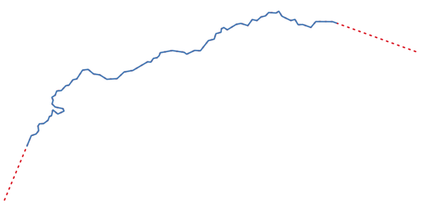
The red dashes represent the initial and final extension of the original layer
Allows
features in-place modification
See also
Parameters
Label |
Name |
Type |
Description |
|---|---|---|---|
Input layer |
|
[vector: line] |
Input line vector layer |
Start distance |
|
[number |
Distance by which to extend the first segment of the line (starting point) |
End distance |
|
[number |
Distance by which to extend the last segment of the line (ending point) |
Extended |
|
[vector: line] Default: |
Specify the output vector layer. One of:
The file encoding can also be changed here. |
Outputs
Label |
Name |
Type |
Description |
|---|---|---|---|
Extended |
|
[vector: line] |
The output (extended) line vector layer. |
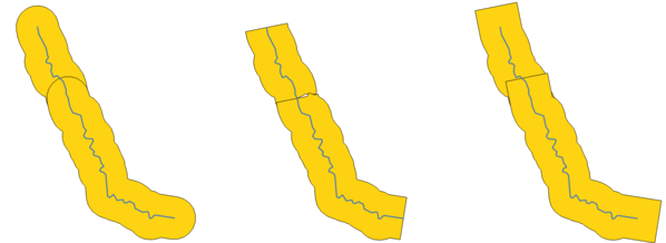
Extract specific vertices
Takes a vector layer and generates a point layer with points representing specific vertices in the input geometries.
For instance, this algorithm can be used to extract the first or last vertices in the geometry. The attributes associated to each point are the same ones associated to the feature that the vertex belongs to.
The vertex indices parameter accepts a comma separated string specifying the indices of the vertices to extract. The first vertex corresponds to an index of 0, the second vertex has an index of 1, etc. Negative indices can be used to find vertices at the end of the geometry, e.g., an index of -1 corresponds to the last vertex, -2 corresponds to the second last vertex, etc.
Additional fields are added to the vertices indicating the specific vertex position (e.g., 0, -1, etc), the original vertex index, the vertex’s part and its index within the part (as well as its ring for polygons), distance along the original geometry and bisector angle of vertex for the original geometry.
Parameters
Label |
Name |
Type |
Description |
|---|---|---|---|
Input layer |
|
[vector: any] |
Input vector layer |
Vertex indices |
|
[string] Default: ‘0’ |
Comma-separated string of the indices of the vertices to extract. |
Vertices |
|
[vector: point] Default: |
Specify the output vector layer. One of:
The file encoding can also be changed here. |
Outputs
Label |
Name |
Type |
Description |
|---|---|---|---|
Vertices |
|
[vector: point] |
The output (point) vector layer containing the specified vertices from the input layer geometries. |
Extract vertices
Takes a vector layer and generates a point layer with points representing the vertices in the input geometries.
The attributes associated to each point are the same ones associated to the feature that the vertex belongs to.
Additional fields are added to the vertices indicating the vertex index (beginning at 0), the feature’s part and its index within the part (as well as its ring for polygons), distance along original geometry and bisector angle of vertex for original geometry.
Vertices extracted for line and polygon layer
Default menu:
Parameters
Label |
Name |
Type |
Description |
|---|---|---|---|
Input layer |
|
[vector: any] |
Input vector layer |
Vertices |
|
[vector: point] Default: |
Specify the output vector layer. One of:
The file encoding can also be changed here. |
Outputs
Label |
Name |
Type |
Description |
|---|---|---|---|
Vertices |
|
[vector: point] |
The output (point) vector layer containing the vertices from the input layer geometries. |
Filter vertices by M value
Filters away vertices based on their M value, returning geometries with only vertex points that have a M value greater than or equal to the specified minimum value and/or less than or equal to the maximum value.
If the minimum value is not specified then only the maximum value is tested, and similarly if the maximum value is not specified then only the minimum value is tested.
The red line represents the black line with only vertices whose M value is <=10.
Note
Depending on the input geometry attributes and the filters used, the resultant geometries created by this algorithm may no longer be valid.
Parameters
Label |
Name |
Type |
Description |
|---|---|---|---|
Input layer |
|
[vector: line, polygon] |
Input line or polygon vector layer to remove vertices from |
Minimum Optional |
|
[number Default: Not set |
Minimum of M values allowed |
Maximum Optional |
|
[number Default: Not set |
Maximum of M values allowed |
Filtered |
|
[same as input] Default: |
Specify the output vector layer. One of:
The file encoding can also be changed here. |
Outputs
Label |
Name |
Type |
Description |
|---|---|---|---|
Filtered |
|
[same as input] |
The output vector layer of features with only the filtered vertices. |
Filter vertices by Z value
Filters away vertices based on their Z value, returning geometries with only vertex points that have a Z value greater than or equal to the specified minimum value and/or less than or equal to the maximum value.
If the minimum value is not specified then only the maximum value is tested, and similarly if the maximum value is not specified then only the minimum value is tested.
The red line represents the black line with only vertices whose Z value is <=10.
Note
Depending on the input geometry attributes and the filters used, the resultant geometries created by this algorithm may no longer be valid. You may need to run the Fix geometries algorithm to ensure their validity.
Parameters
Label |
Name |
Type |
Description |
|---|---|---|---|
Input layer |
|
[vector: line, polygon] |
Input line or polygon vector layer to remove vertices from |
Minimum Optional |
|
[number Default: Not set |
Minimum of Z values allowed |
Maximum Optional |
|
[number Default: Not set |
Maximum of Z values allowed |
Filtered |
|
[same as input] Default: |
Specify the output vector layer. One of:
The file encoding can also be changed here. |
Outputs
Label |
Name |
Type |
Description |
|---|---|---|---|
Filtered |
|
[same as input] |
The output vector layer of features with only the filtered vertices. |
Fix geometries
Attempts to create a valid representation of a given invalid geometry without losing any of the input vertices. Already valid geometries are returned without further intervention. Always outputs multi-geometry layer.
Note
M values will be dropped from the output.
Allows
features in-place modification
See also
Parameters
Label |
Name |
Type |
Description |
|---|---|---|---|
Input layer |
|
[vector: any] |
Input vector layer |
Fixed geometries |
|
[same as input] Default: |
Specify the output vector layer. One of:
The file encoding can also be changed here. |
Outputs
Label |
Name |
Type |
Description |
|---|---|---|---|
Fixed geometries |
|
[same as input] |
The output vector layer with fixed geometries. |
Geometry by expression
Updates existing geometries (or creates new geometries) for input features by use of a QGIS expression.
This allows complex geometry modifications which can utilize all the flexibility of the QGIS expression engine to manipulate and create geometries for output features.
For help with QGIS expression functions, see the inbuilt help available in the expression builder.
Parameters
Label |
Name |
Type |
Description |
|---|---|---|---|
Input layer |
|
[vector: any] |
Input vector layer |
Output geometry type |
|
[enumeration] Default: 0 |
The output geometry strongly depends on the expression: for instance, if you create a buffer the geometry type has to be polygon. One of:
|
Output geometry has z values |
|
[boolean] Default: False |
Choose if the output geometry should include the Z dimension |
Output geometry has m values |
|
[boolean] Default: False |
Choose if the output geometry should include the M dimension |
Geometry expression |
|
[expression] Default: ‘$geometry’ |
Add the geometry expression you want to use. You can use the button to open the Expression Dialog. The dialog lists all the relevant expressions, together with their help and guide. |
Modified geometry |
|
[vector: any] Default: |
Specify the output vector layer. One of:
The file encoding can also be changed here. |
Outputs
Label |
Name |
Type |
Description |
|---|---|---|---|
Modified geometry |
|
[vector: any] |
The output vector layer |
Interpolate point on line
Creates a point geometry interpolated at a set distance along line or curve geometries.
Z and M values are linearly interpolated from existing values.
If a multipart geometry is encountered, only the first part is considered when calculating the substring.
If the specified distance is greater than the input feature’s length, the resultant feature will have a null geometry.
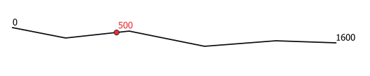
Interpolated point at 500m of the beginning of the line
See also
Parameters
Label |
Name |
Type |
Description |
|---|---|---|---|
Input layer |
|
[vector: line, polygon] |
Input line or polygon vector layer |
Distance |
|
[number Default: 0.0 |
Distance from the beginning of the line |
Interpolated points |
|
[vector: point] Default: |
Specify the output vector layer. One of:
The file encoding can also be changed here. |
Outputs
Label |
Name |
Type |
Description |
|---|---|---|---|
Interpolated points |
|
[vector: point] |
The output point vector layer with features at a set distance along the line or polygon boundary |
Keep N biggest parts
Takes a layer with polygons or multipolygons and returns a new layer in which only the n largest polygons of each multipolygon feature are kept. If a feature has n or fewer parts, the feature will just be copied.
Clockwise from top left: original multipart feature, one, two and three biggest parts kept
Parameters
Label |
Name |
Type |
Description |
|---|---|---|---|
Polygons |
|
[vector: polygon] |
Input polygon vector layer |
Parts to keep |
|
[number] Default: 1 |
Number of parts to keep. If 1, only the biggest part of the feature will be kept. |
Parts |
|
[vector: polygon] Default: |
Specify the output polygon vector layer. One of:
The file encoding can also be changed here. |
Outputs
Label |
Name |
Type |
Description |
|---|---|---|---|
Parts |
|
[vector: polygon] |
The output polygon vector layer with the N biggest parts of each feature |
Line substring
Returns the portion of a line (or curve) which falls between the specified start and end distances (measured from the beginning of the line).
Z and M values are linearly interpolated from existing values.
If a multipart geometry is encountered, only the first part is considered when calculating the substring.
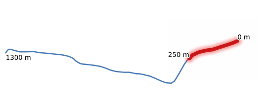
Substring line with starting distance set at 0 meters and the ending distance at 250 meters.
Allows features in-place modification
See also
Parameters
Label |
Name |
Type |
Description |
|---|---|---|---|
Input layer |
|
[vector: line] |
Input line vector layer |
Start distance |
|
[number |
Distance along the input line to the start point of the output feature |
End distance |
|
[number |
Distance along the input line to the end point of the output feature |
Substring |
|
[vector: line] Default: |
Specify the output line vector layer. One of:
The file encoding can also be changed here. |
Outputs
Label |
Name |
Type |
Description |
|---|---|---|---|
Substring |
|
[vector: line] |
The output line vector layer. |
Lines to polygons
Generates a polygon layer using as polygon rings the lines from an input line layer.
The attribute table of the output layer is the same as the one from of the input line layer.
Default menu:
See also
Parameters
Label |
Name |
Type |
Description |
|---|---|---|---|
Input layer |
|
[vector: line] |
Input line vector layer |
Polygons |
|
[vector: polygon] Default: |
Specify the output polygon vector layer. One of:
The file encoding can also be changed here. |
Outputs
Label |
Name |
Type |
Description |
|---|---|---|---|
Polygons |
|
[vector: polygon] |
The output polygon vector layer. |
Merge lines
Joins all connected parts of MultiLineString geometries into single LineString geometries.
If any parts of the input MultiLineString geometries are not connected, the resultant geometry will be a MultiLineString containing any lines which could be merged and any non-connected line parts.
Allows
features in-place modification
Parameters
Label |
Name |
Type |
Description |
|---|---|---|---|
Input layer |
|
[vector: line] |
Input line vector layer |
Merged |
|
[vector: line] Default: |
Specify the output line vector layer. One of:
The file encoding can also be changed here. |
Outputs
Label |
Name |
Type |
Description |
|---|---|---|---|
Merged |
|
[vector: line] |
The output (merged) line vector layer. |
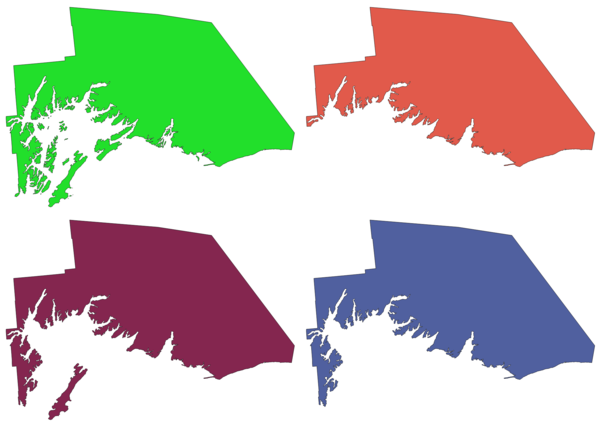
Minimum bounding geometry
Creates geometries which enclose the features from an input layer. The features can be grouped by a field. The output layer will then contain one feature per group value with a geometry (MBB) that covers the geometries of the features with matching value.
The following enclosing geometry types are supported:
bounding box (envelope)
oriented rectangle
circle
convex hull
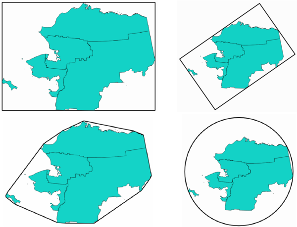
Clockwise from top left: envelope, oriented rectangle, circle, convex hull
See also
Parameters
Label |
Name |
Type |
Description |
|---|---|---|---|
Input layer |
|
[vector: any] |
Input vector layer |
Field Optional |
|
[tablefield: any] |
Features can be grouped by a field. If set, this causes the output layer to contain one feature per grouped value with a minimal geometry covering only the features with matching values. |
Geometry type |
|
[enumeration] Default: 0 |
Enclosing geometry types. One of:
|
Bounding geometry |
|
[vector: polygon] Default: |
Specify the output polygon vector layer. One of:
The file encoding can also be changed here. |
Outputs
Label |
Name |
Type |
Description |
|---|---|---|---|
Bounding geometry |
|
[vector: polygon] |
The output (bounding) polygon vector layer. |
Minimum enclosing circles
Calculates the minimum enclosing circles of the features in the input layer.
Enclosing circles for each feature
Allows
features in-place modification
See also
Parameters
Label |
Name |
Type |
Description |
|---|---|---|---|
Input layer |
|
[vector: any] |
Input vector layer |
Number of segment in circles |
|
[number] Default: 72 |
The number of segment used to approximate a circle. Minimum 8, maximum 100000. |
Minimum enclosing circles |
|
[vector: polygon] Default: |
Specify the output polygon vector layer. One of:
The file encoding can also be changed here. |
Outputs
Label |
Name |
Type |
Description |
|---|---|---|---|
Minimum enclosing circles |
|
[vector: polygon] |
The output polygon vector layer. |
Multi-ring buffer (constant distance)
Computes multi-ring (donut) buffer for the features of the input layer, using a fixed or dynamic distance and number of rings.
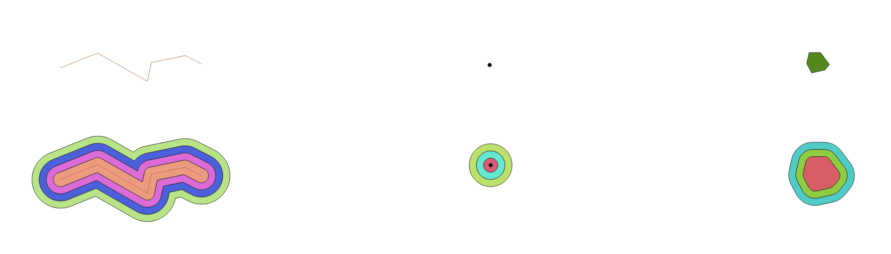
Multi-ring buffer for a line, point and polygon layer
Allows
features in-place modification
See also
Buffer, Variable distance buffer (Graphical Modeler only), Rectangles, ovals, diamonds (fixed), Rectangles, ovals, diamonds (variable), Single sided buffer
Parameters
Label |
Name |
Type |
Description |
|---|---|---|---|
Input layer |
|
[vector: any] |
Input vector layer |
Number of rings |
|
[number Default: 1 |
The number of rings. It can be a unique value (same number of rings for all the features) or it can be taken from features data (the number of rings depends on feature values). |
Distance between rings |
|
[number Default: 1.0 |
Distance between the rings. It can be a unique value (same distance for all the features) or it can be taken from features data (the distance depends on feature values). |
Multi-ring buffer (constant distance) |
|
[vector: polygon] Default: |
Specify the output polygon vector layer. One of:
The file encoding can also be changed here. |
Outputs
Label |
Name |
Type |
Description |
|---|---|---|---|
Multi-ring buffer (constant distance) |
|
[vector: polygon] |
The output polygon vector layer. |
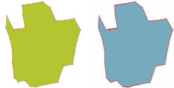
Multipart to singleparts
Splits multipart features in the input layer into singlepart features.
The attributes of the output layer are the same as the original ones but divided into single features.
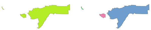
Left the multipart source layer and right the single part output result
Allows
features in-place modification
Default menu:
See also
Parameters
Label |
Name |
Type |
Description |
|---|---|---|---|
Input layer |
|
[vector: any] |
Input vector layer |
Single parts |
|
[same as input] Default: |
Specify the output polygon vector layer. One of:
The file encoding can also be changed here. |
Outputs
Label |
Name |
Type |
Description |
|---|---|---|---|
Single parts |
|
[same as input] |
The output vector layer. |
Offset lines
Offsets lines by a specified distance. Positive distances will offset lines to the left, and negative distances will offset them to the right.
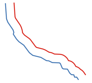
In blue the source layer, in red the offset one
Allows
features in-place modification
See also
Parameters
Label |
Name |
Type |
Description |
|---|---|---|---|
Input layer |
|
[vector: line] |
Input line vector layer |
Distance |
|
[number Default: 10.0 |
Offset distance. You can use the Data Defined button on the right to choose a field from which the radius will be calculated. This way you can have different radius for each feature (see Variable distance buffer (Graphical Modeler only)). |
Segments |
|
[number] Default: 8 |
Controls the number of line segments to use to approximate a quarter circle when creating rounded offsets. |
Join style |
|
[enumeration] Default: 0 |
Specifies whether round, miter or beveled joins should be used when offsetting corners in a line. Options are:
|
Miter limit |
|
[number] Default: 2.0 |
Controls the maximum distance from the offset curve to use when creating a mitered join (only applicable for miter join styles). Minimum: 1. |
Offset |
|
[vector: line] Default: |
Specify the output (offset) layer. One of:
The file encoding can also be changed here. |
Outputs
Label |
Name |
Type |
Description |
|---|---|---|---|
Offset |
|
[vector: line] |
Output (offset) line layer |
Oriented minimum bounding box
Calculates the minimum area rotated rectangle for each feature in the input layer.
Oriented minimum bounding box
Allows
features in-place modification
See also
Parameters
Label |
Name |
Type |
Description |
|---|---|---|---|
Input layer |
|
[vector: any] |
Input vector layer |
Bounding boxes |
|
[vector: polygon] Default: |
Specify the output polygon vector layer. One of:
The file encoding can also be changed here. |
Outputs
Label |
Name |
Type |
Description |
|---|---|---|---|
Bounding boxes |
|
[vector: polygon] |
The output polygon vector layer. |
Orthogonalize
Attempts to orthogonalize the geometries of the input line or polygon layer. This process shifts the vertices in the geometries to try to make every angle in the geometry either a right angle or a straight line.
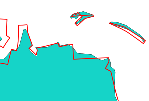
In blue the source layer and in the red orthogonalized result
Allows
features in-place modification
Parameters
Label |
Name |
Type |
Description |
|---|---|---|---|
Input layer |
|
[vector: line, polygon] |
Input line or polygon vector layer |
Maximum angle tolerance (degrees) |
|
[number] Default: 15 |
Specify the maximum deviation from a right angle or straight line a vertex can have for it to be adjusted. Smaller tolerances mean that only vertices which are already closer to right angles will be adjusted, and larger tolerances mean that vertices which deviate further from right angles will also be adjusted. |
Maximum algorithm iterations |
|
[number] Default: 1000 |
Setting a larger number for the maximum number of iterations will result in a more orthogonal geometry at the cost of extra processing time. |
Orthogonalized |
|
[same as input] Default: |
Specify the output polygon vector layer. One of:
The file encoding can also be changed here. |
Outputs
Label |
Name |
Type |
Description |
|---|---|---|---|
Orthogonalized |
|
[same as input] |
The output polygon vector layer with adjusted angles. |
Point on Surface
For each feature of the input layer, returns a point that is guaranteed to lie on the surface of the feature geometry.
Allows
features in-place modification
See also
Parameters
Label |
Name |
Type |
Description |
|---|---|---|---|
Input layer |
|
[vector: any] |
Input vector layer |
Create point on surface for each part |
|
[boolean |
If checked, a point will be created for each part of the geometry. |
Point |
|
[vector: point] Default: |
Specify the output point vector layer. One of:
The file encoding can also be changed here. |
Outputs
Label |
Name |
Type |
Description |
|---|---|---|---|
Point |
|
[vector: point] |
The output point vector layer. |
Points along geometry
Creates points at regular intervals along line or polygon geometries. Created points will have new attributes added for the distance along the geometry and the angle of the line at the point.
An optional start and end offset can be specified, which controls how far from the start and end of the geometry the points should be created.
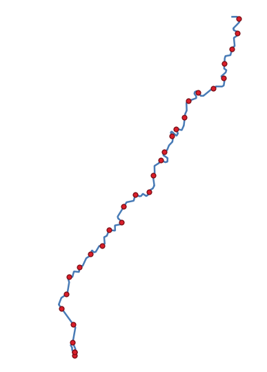
Points created along the source line layer
See also
Parameters
Label |
Name |
Type |
Description |
|---|---|---|---|
Input layer |
|
[vector: line, polygon] |
Input line or polygon vector layer |
Distance |
|
[number Default: 1.0 |
Distance between two consecutive points along the line |
Start offset |
|
[number Default: 0.0 |
Distance from the beginning of the input line, representing the position of the first point. |
End offset |
|
[number Default: 0.0 |
Distance from the end of the input line, representing the position beyond which no point feature shoud be created. |
Interpolated points |
|
[vector: point] Default: |
Specify the output vector layer. One of:
The file encoding can also be changed here. |
Outputs
Label |
Name |
Type |
Description |
|---|---|---|---|
Interpolated points |
|
[vector: point] |
Point vector layer with features placed along lines or polygon boundaries of the input layer. |
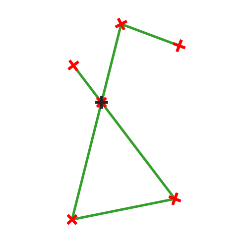
Points displacement
Given a distance of proximity, identifies nearby point features and radially distributes them over a circle whose center represents their barycenter. A convenient tool to scatter overlaid features.
Parameters
Label |
Name |
Type |
Description |
|---|---|---|---|
Input layer |
|
[vector: point] |
Input point vector layer |
Minimum distance to other points |
|
[number] Default: 1.0 |
Distance below which point features are considered close. Close features are distributed altogether. |
Displacement distance |
|
[number] Default: 1.0 |
Radius of the circle on which close features are placed |
Horizontal distribution for two point case |
|
[boolean] Default: False |
When only two points are identified as close, aligns them horizontally on the circle instead of vertically. |
Displaced |
|
[vector: point] Default: |
Specify the output vector layer. One of:
The file encoding can also be changed here. |
Outputs
Label |
Name |
Type |
Description |
|---|---|---|---|
Displaced |
|
[vector: point] |
Output point vector layer |
Pole of inaccessibility
Calculates the pole of inaccessibility for a polygon layer, which is the most distant internal point from the boundary of the surface.
This algorithm uses the ‘polylabel’ algorithm (Vladimir Agafonkin, 2016), which is an iterative approach guaranteed to find the true pole of inaccessibility within a specified tolerance. A more precise tolerance (lower value) requires more iterations and will take longer to calculate.
The distance from the calculated pole to the polygon boundary will be stored as a new attribute in the output layer.
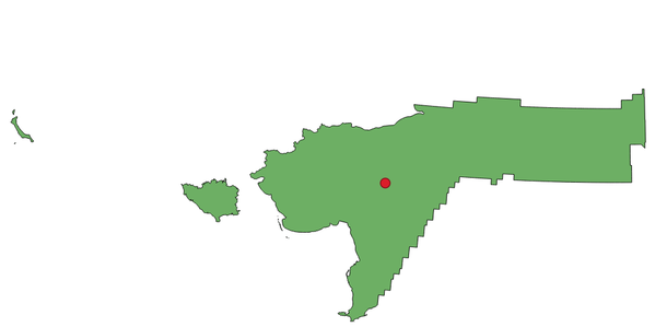
Pole of inaccessibility
Parameters
Label |
Name |
Type |
Description |
|---|---|---|---|
Input layer |
|
[vector: polygon] |
Input vector layer |
Tolerance |
|
[number] Default: 1.0 |
Set the tolerance for the calculation |
Point |
|
[vector: point] Default: |
Specify the output polygon vector layer. One of:
The file encoding can also be changed here. |
Outputs
Label |
Name |
Type |
Description |
|---|---|---|---|
Point |
|
[vector: point] |
The output point vector layer |
Polygonize
Creates a polygon layer whose features boundaries are generated from a line layer of closed features.
The yellow polygons generated from the closed lines
Note
The line layer must have closed shapes in order to be transformed into a polygon.
See also
Parameters
Label |
Name |
Type |
Description |
|---|---|---|---|
Input layer |
|
[vector: line] |
Input line vector layer |
Keep table structure of line layer Optional |
|
[boolean] Default: False |
Check to copy the original attributes of the input layer |
Polygons from lines |
|
[vector: polygon] Default: |
Specify the output polygon vector layer. One of:
The file encoding can also be changed here. |
Outputs
Label |
Name |
Type |
Description |
|---|---|---|---|
Polygons from lines |
|
[vector: polygon] |
The output polygon vector layer from lines |
Polygons to lines
Takes a polygon layer and creates a line layer, with lines representing the boundaries of the polygons in the input layer.
Black lines as the result of the algorithm
Default menu:
See also
Parameters
Label |
Name |
Type |
Description |
|---|---|---|---|
Input layer |
|
[vector: polygon] |
Input polygon vector layer |
Lines |
|
[vector: line] Default: |
Specify the output line vector layer. One of:
The file encoding can also be changed here. |
Outputs
Label |
Name |
Type |
Description |
|---|---|---|---|
Lines |
|
[vector: line] |
The output line vector layer from polygons |
Project points (Cartesian)
Projects point geometries by a specified distance and bearing (azimuth).
Allows
features in-place modification
Parameters
Label |
Name |
Type |
Description |
|---|---|---|---|
Input layer |
|
[vector: point] |
Input point vector layer |
Bearing (degrees from North) |
|
[number Default: 0.0 |
Clockwise angle starting from North, in degree (°) unit |
Distance |
|
[number Default: 1.0 |
Distance to offset geometries, in layer units |
Projected |
|
[vector: point] Default: |
Specify the output point vector layer. One of:
The file encoding can also be changed here. |
Outputs
Label |
Name |
Type |
Description |
|---|---|---|---|
Projected |
|
[vector: point] |
The output (projected) point vector layer |
Promote to multipart
Takes a vector layer with singlepart geometries and generates a new one in which all geometries are multipart.
Input features which are already multipart features will remain unchanged.
This algorithm can be used to force geometries to multipart types in order to be compatible with data providers that require multipart features.
Allows
features in-place modification
See also
Parameters
Label |
Name |
Type |
Description |
|---|---|---|---|
Input layer |
|
[vector: any] |
Input vector layer |
Multiparts |
|
[same as input] Default: |
Specify the output multipart vector layer. One of:
The file encoding can also be changed here. |
Outputs
Label |
Name |
Type |
Description |
|---|---|---|---|
Multiparts |
|
[same as input] |
The output multipart vector layer |
Rectangles, ovals, diamonds (fixed)
Creates a buffer area for all the features in an input layer with different shape choice.
Parameters can vary depending on the shape chosen.
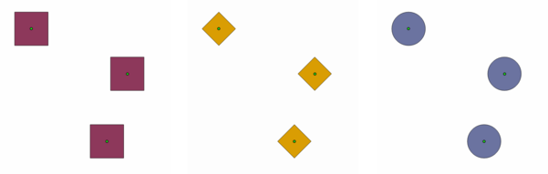
Different buffer shapes
Parameters
Label |
Name |
Type |
Description |
|---|---|---|---|
Input layer |
|
[vector: point] |
Input point vector layer |
Buffer shape |
|
[enumeration] |
The shape to use. One of:
|
Width |
|
[number] Default: 1.0 |
Width of the buffer shape |
Height |
|
[number] Default: 1.0 |
Height of the buffer shape |
Rotation Optional |
|
[number] Default: None |
Rotation of the buffer shape |
Number of segment |
|
[number] Default: 36 |
Number of segments for a full circle (Ovals shape) |
Output |
|
[vector: polygon] Default: |
Specify the output vector layer. One of:
The file encoding can also be changed here. |
Outputs
Label |
Name |
Type |
Description |
|---|---|---|---|
Output |
|
[vector: polygon] |
The output vector layer (with the buffer shapes) |
Rectangles, ovals, diamonds (variable)
Creates a buffer area for all the features in an input layer with different shape choice.
Buffer shape parameters are specified through attribute of the input layer.
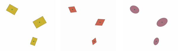
Different buffer shapes with different parameters
See also
Parameters
Label |
Name |
Type |
Description |
|---|---|---|---|
Input layer |
|
[vector: point] |
Input point vector layer |
Buffer shape |
|
[enumeration] Default: 0 |
The shape to use. One of:
|
Width field |
|
[tablefield: numeric] Default: First |
Width of the buffer shape |
Height field |
|
[tablefield: numeric] Default: First |
Height of the buffer shape |
Rotation field Optional |
|
[tablefield: numeric] |
Rotation of the buffer shape |
Number of segment |
|
[number] Default: 36 |
Number of segments for a full circle (Ovals shape) |
Output |
|
[vector: polygon] Default: |
Specify the output vector layer. One of:
The file encoding can also be changed here. |
Outputs
Label |
Name |
Type |
Description |
|---|---|---|---|
Output |
|
[vector: polygon] |
The output vector layer (with the buffer shapes) |
Remove duplicate vertices
Removes duplicate vertices from features, wherever removing the vertices does not result in a degenerate geometry.
The tolerance parameter specifies the tolerance for coordinates when determining whether vertices are identical.
By default, Z values are not considered when detecting duplicate vertices. E.g. two vertices with the same X and Y coordinate but different Z values will still be considered duplicate and one will be removed. If the :guilabel;`Use Z Value` parameter is true, then the Z values are also tested and vertices with the same X and Y but different Z will be maintained.
Note
Duplicate vertices are not tested between different parts of a multipart geometry, e.g. a multipoint geometry with overlapping points will not be changed by this method.
Allows features in-place modification
Parameters
Label |
Name |
Type |
Description |
|---|---|---|---|
Input layer |
|
[vector: any] |
Input vector layer |
Tolerance |
|
[number Default: 0.000001 |
Vertices closer than the specified distance are considered duplicates |
Use Z value |
|
[boolean Default: False |
If the :guilabel;`Use Z Value` parameter is true, then the Z values are also tested and vertices with the same X and Y but different Z will be maintained. |
Cleaned |
|
[same as input] Default: |
Specify the output vector layer. One of:
The file encoding can also be changed here. |
Outputs
Label |
Name |
Type |
Description |
|---|---|---|---|
Cleaned |
|
[same as input] |
The output vector layer (without duplicate vertices) |
Remove null geometries
Removes any features which do not have a geometry from a vector layer.
All other features will be copied unchanged.
The features with null geometries can be saved to a separate layer.
See also
Parameters
Label |
Name |
Type |
Description |
|---|---|---|---|
Input layer |
|
[vector: any] |
Input vector layer (with non-NULL geometries) |
Non null geometries |
|
[same as input] Default: |
Specify the output vector layer for the non-NULL geometries. One of:
The file encoding can also be changed here. |
Null geometries |
|
[same as input] Default: |
Specify the output vector layer for the NULL geometries. One of:
The file encoding can also be changed here. |
Outputs
Label |
Name |
Type |
Description |
|---|---|---|---|
Null geometries |
|
[same as input] |
The output vector layer (only NULL geometries) |
Non null geometries |
|
[same as input] |
The output vector layer (without NULL geometries) |
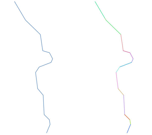
Reverse line direction
Inverts the direction of a line layer.
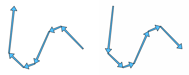
Before and after the direction inversion
Allows features in-place modification
Parameters
Label |
Name |
Type |
Description |
|---|---|---|---|
Input layer |
|
[vector: line] |
Input line vector layer |
Reversed |
|
[vector: line] Default: |
Specify the output line vector layer. One of:
The file encoding can also be changed here. |
Outputs
Label |
Name |
Type |
Description |
|---|---|---|---|
Reversed |
|
[vector: line] |
The output line vector layer (with reversed lines) |
Rotate
Rotates feature geometries by the specified angle clockwise. The rotation occurs around each feature’s centroid, or optionally around a unique preset point.
Allows
features in-place modification
See also
Parameters
Label |
Name |
Type |
Description |
|---|---|---|---|
Input layer |
|
[vector: any] |
Input vector layer |
Rotation (degrees clockwise) |
|
[number Default: 0.0 |
Angle of the rotation in degrees |
Rotation anchor point (x, y) Optional |
|
[point] Default: None |
X,Y coordinates of the point to rotate the features around. If not set the rotation occurs around each feature’s centroid. |
Rotated |
|
[same as input] Default: |
Specify the output vector layer (with rotated geometries). One of:
The file encoding can also be changed here. |
Outputs
Label |
Name |
Type |
Description |
|---|---|---|---|
Rotated |
|
[same as input] |
The output vector layer with rotated geometries |
Segmentize by maximum angle
Segmentizes a geometry by converting curved sections to linear sections.
The segmentization is performed by specifying the maximum allowed radius angle between vertices on the straightened geometry (e.g the angle of the arc created from the original arc center to consecutive output vertices on the linearized geometry). Non-curved geometries will be retained without change.
See also
Parameters
Label |
Name |
Type |
Description |
|---|---|---|---|
Input layer |
|
[vector: line, polygon] |
Input line or polygon vector layer |
Maximum angle between vertices (degrees) |
|
[number Default: 5.0 |
Maximum allowed radius angle between vertices on the straightened geometry |
Segmentized |
|
[same as input] Default: |
Specify the output vector layer (with segmentized geometries). One of:
The file encoding can also be changed here. |
Outputs
Label |
Name |
Type |
Description |
|---|---|---|---|
Segmentized |
|
[same as input] |
The output vector layer with segmentized geometries |
Segmentize by maximum distance
Segmentizes a geometry by converting curved sections to linear sections.
The segmentization is performed by specifying the maximum allowed offset distance between the original curve and the segmentized representation. Non-curved geometries will be retained without change.
See also
Parameters
Label |
Name |
Type |
Description |
|---|---|---|---|
Input layer |
|
[vector: line, polygon] |
Input line or polygon vector layer |
Maximum offset distance |
|
[number Default: 1.0 |
Maximum allowed offset distance between the original curve and the segmentized representation, in the layer units. |
Segmentized |
|
[same as input] Default: |
Specify the output vector layer (with segmentized geometries). One of:
The file encoding can also be changed here. |
Outputs
Label |
Name |
Type |
Description |
|---|---|---|---|
Segmentized |
|
[same as input] |
The output vector layer with segmentized geometries |
Set M value
Sets the M value for geometries in a layer.
If M values already exist in the layer, they will be overwritten with the new value. If no M values exist, the geometry will be upgraded to include M values and the specified value used as the initial M value for all geometries.
Tip
Use the  Identify Features button to check
the added M value: the results are available in the
Identify Results dialog.
Identify Features button to check
the added M value: the results are available in the
Identify Results dialog.
See also
Parameters
Label |
Name |
Type |
Description |
|---|---|---|---|
Input layer |
|
[vector: any] |
Input vector layer |
M Value |
|
[number Default: 0.0 |
M value to assign to the feature geometries |
M Added |
|
[same as input] Default: |
Specify the output vector layer. One of:
The file encoding can also be changed here. |
Outputs
Label |
Name |
Type |
Description |
|---|---|---|---|
M Added |
|
[same as input] |
The output vector layer (with M values assigned to the geometries) |
Set M value from raster
Uses values sampled from a band within a raster layer to set the M value for every overlapping vertex in the feature geometry. The raster values can optionally be scaled by a preset amount.
If M values already exist in the layer, they will be overwritten with the new value. If no M values exist, the geometry will be upgraded to include M values.
See also
Parameters
Label |
Name |
Type |
Description |
|---|---|---|---|
Input layer |
|
[vector: any] |
Input vector layer |
Raster layer |
|
[raster] |
Raster layer with M values |
Band number |
|
[raster band] Default: 1 |
The raster band from which the M values are taken |
Value for nodata or non-intersecting vertices |
|
[number |
Value to use in case the vertex does not intersect (a valid pixel of) the raster |
Scale factor |
|
[number Default: 1.0 |
Scaling value: the band values are multiplied by this value. |
Updated |
|
[same as input] Default: |
Specify the output vector layer (with updated M values). One of:
The file encoding can also be changed here. |
Outputs
Label |
Name |
Type |
Description |
|---|---|---|---|
Updated |
|
[same as input] |
The output vector layer (with updated M values) |
Set Z value
Sets the Z value for geometries in a layer.
If Z values already exist in the layer, they will be overwritten with the new value. If no Z values exist, the geometry will be upgraded to include Z values and the specified value used as the initial Z value for all geometries.
Tip
Use the Identify Features button to check
the added Z value: the results are available in the
Identify Results dialog.
See also
Parameters
Label |
Name |
Type |
Description |
|---|---|---|---|
Input layer |
|
[vector: any] |
Input vector layer |
Z Value |
|
[number Default: 0.0 |
Z value to assign to the feature geometries |
Z Added |
|
[same as input] Default: |
Specify the output vector layer. One of:
The file encoding can also be changed here. |
Outputs
Label |
Name |
Type |
Description |
|---|---|---|---|
Z Added |
|
[same as input] |
The output vector layer (with Z values assigned) |
Simplify
Simplifies the geometries in a line or polygon layer. It creates a new layer with the same features as the ones in the input layer, but with geometries containing a lower number of vertices.
The algorithm gives a choice of simplification methods, including distance based (the “Douglas-Peucker” algorithm), area based (“Visvalingam” algorithm) and snapping geometries to grid.
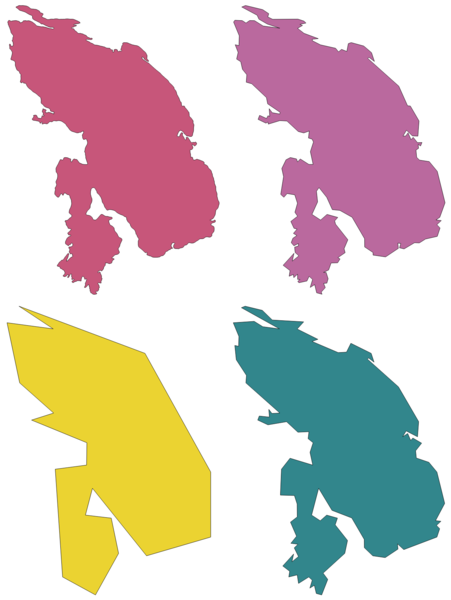
Clockwise from top left: source layer and increasing simplification tolerances
Allows features in-place modification
Default menu:
See also
Parameters
Label |
Name |
Type |
Description |
|---|---|---|---|
Input layer |
|
[vector: line, polygon] |
Input line or polygon vector layer |
Simplification method |
|
[enumeration] Default: 0 |
Simplification method. One of:
|
Tolerance |
|
[number Default: 1.0 |
Threshold tolerance (in units of the layer): if the distance between two nodes is smaller than the tolerance value, the segment will be simplified and vertices will be removed. |
Simplified |
|
[same as input] Default: |
Specify the output (simplified) vector layer. One of:
The file encoding can also be changed here. |
Outputs
Label |
Name |
Type |
Description |
|---|---|---|---|
Simplified |
|
[same as input] |
The output (simplified) vector layer |
Single sided buffer
Computes a buffer on lines by a specified distance on one side of the line only.
Buffer always results in a polygon layer.
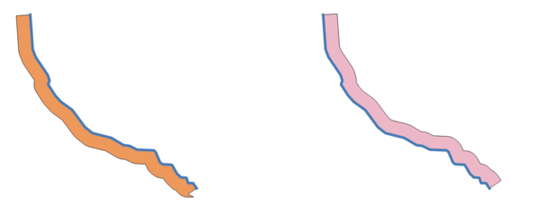
Left versus right side buffer on the same vector line layer
See also
Parameters
Label |
Name |
Type |
Description |
|---|---|---|---|
Input layer |
|
[vector: any] |
Input vector layer |
Distance |
|
[number] Default: 10.0 |
Buffer distance (from the boundary of each feature). |
Side |
|
[enumeration] |
Which side to create the buffer on. One of:
|
Segments |
|
[number] Default: 8 |
Controls the number of line segments to use to approximate a quarter circle when creating rounded offsets. |
Join style |
|
[enumeration] |
Specifies whether round, miter or beveled joins should be used when offsetting corners in a line. Options are:
|
Miter limit |
|
[number] Default: 2.0 |
Controls the maximum distance from the offset curve to use when creating a mitered join (only applicable for miter join styles). Minimum: 1.0 |
Buffer |
|
[vector: polygon] Default: |
Specify the output (buffer) layer. One of:
The file encoding can also be changed here. |
Outputs
Label |
Name |
Type |
Description |
|---|---|---|---|
Buffer |
|
[vector: polygon] |
Output (buffer) polygon layer |
Smooth
Smooths the geometries in a line or polygon layer. It creates a new layer with the same features as the ones in the input layer, but with geometries containing a higher number of vertices and corners in the geometries smoothed out.
The iterations parameter dictates how many smoothing iterations will be applied to each geometry. A higher number of iterations results in smoother geometries with the cost of greater number of nodes in the geometries.
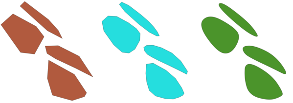
Increasing number of iterations causes smoother geometries
The offset parameter controls how “tightly” the smoothed geometries follow the original geometries. Smaller values results in a tighter fit, and larger values will create a looser fit.
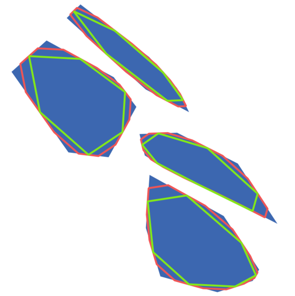
Blue: the input layer. Offset 0.25 gives the red line, while offset 0.50 gives the green line.
The maximum angle parameter can be used to prevent smoothing of nodes with large angles. Any node where the angle of the segments to either side is larger than this will not be smoothed. For example, setting the maximum angle to 90 degrees or lower would preserve right angles in the geometry.
Allows
features in-place modification
See also
Parameters
Label |
Name |
Type |
Description |
|---|---|---|---|
Input layer |
|
[vector: line, polygon] |
Input line or polygon vector layer |
Iterations |
|
[number Default: 1 |
Increasing the number of iterations will give smoother geometries (and more vertices). |
Offset |
|
[number Default: 0.25 |
Increasing values will move the smoothed lines / boundaries further away from the input lines / booundaries. |
Maximum node angle to smooth |
|
[number Default: 180.0 |
Every node below this value will be smoothed |
Smoothed |
|
[same as input] Default: |
Specify the output (buffer) layer. One of:
The file encoding can also be changed here. |
Outputs
Label |
Name |
Type |
Description |
|---|---|---|---|
Smoothed |
|
[same as input] |
Output (smoothed) vector layer |
Snap geometries to layer
Snaps the geometries in a layer either to the geometries from another layer, or to geometries within the same layer.
Matching is done based on a tolerance distance, and vertices will be inserted or removed as required to make the geometries match the reference geometries.
See also
Parameters
Label |
Name |
Type |
Description |
|---|---|---|---|
Input layer |
|
[vector: any] |
Input vector layer |
Reference layer |
|
[vector: any] |
Vector layer to snap to |
Tolerance |
|
[number] Default: 10.0 |
Control how close input vertices need to be to the reference layer geometries before they are snapped. This distance is specified in layer units. |
Behavior* |
|
[enumeration] Default: 0 |
Snapping can be done to an existing node or a segment (its closest point to the vertex to move). Available snapping options:
|
Snapped geometry |
|
[same as input] Default: |
Specify the output (buffer) layer. One of:
The file encoding can also be changed here. |
Outputs
Label |
Name |
Type |
Description |
|---|---|---|---|
Snapped geometry |
|
[same as input] |
Output (snapped) vector layer |
Snap points to grid
Modifies the coordinates of geometries in a vector layer, so that all points or vertices are snapped to the closest point of a grid.
If the snapped geometry cannot be calculated (or is totally collapsed) the feature’s geometry will be cleared.
Snapping can be performed on the X, Y, Z or M axis. A grid spacing of 0 for any axis will disable snapping for that axis.
Note
Snapping to grid may generate an invalid geometry in some corner cases.
Allows
features in-place modification
See also
Parameters
Label |
Name |
Type |
Description |
|---|---|---|---|
Input layer |
|
[vector: any] |
Input vector layer |
X Grid Spacing |
|
[number Default: 1.0 |
Grid spacing on the X axis |
Y Grid Spacing |
|
[number Default: 1.0 |
Grid spacing on the Y axis |
Z Grid Spacing |
|
[number Default: 0.0 |
Grid spacing on the Z axis |
M Grid Spacing |
|
[number Default: 0.0 |
Grid spacing on the M axis |
Snapped |
|
[same as input] Default: |
Specify the output (buffer) layer. One of:
The file encoding can also be changed here. |
Outputs
Label |
Name |
Type |
Description |
|---|---|---|---|
Snapped |
|
[same as input] |
Output (snapped) vector layer |
Subdivide
Subdivides the geometry. The returned geometry will be a collection containing subdivided parts from the original geometry, where no part has more than the specified maximum number of nodes.
This is useful for dividing a complex geometry into less complex parts, easier to spatially index and faster to perform spatial operations. Curved geometries will be segmentized before subdivision.
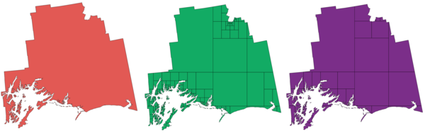
Left the input layer, middle maximum nodes value is 100 and right maximum value is 200
Note
Subdividing a geometry can generate geometry parts that may not be valid and may contain self-intersections.
Allows
features in-place modification
See also
Parameters
Label |
Name |
Type |
Description |
|---|---|---|---|
Input layer |
|
[vector: any] |
The input vector layer |
Maximum nodes in parts |
|
[number Default: 256 |
Maximum number of vertices each new geometry part is allowed to have. Fewer sub-parts for higher values. |
Subdivided |
|
[same as input] Default: |
Specify the output line vector layer. One of:
The file encoding can also be changed here. |
Outputs
Label |
Name |
Type |
Description |
|---|---|---|---|
Subdivided |
|
[same as input] |
Output vector layer |
Swap X and Y coordinates
Switches the X and Y coordinate values in input geometries.
It can be used to repair geometries which have accidentally had their latitude and longitude values reversed.
Allows
features in-place modification
Parameters
Label |
Name |
Type |
Description |
|---|---|---|---|
Input layer |
|
[vector: any] |
The input vector layer |
Swapped |
|
[same as input] Default: |
Specify the output line vector layer. One of:
The file encoding can also be changed here. |
Outputs
Label |
Name |
Type |
Description |
|---|---|---|---|
Swapped |
|
[same as input] |
Output (swapped) vector layer |
Tapered buffers
Creates tapered buffer along line geometries, using a specified start and end buffer diameter.
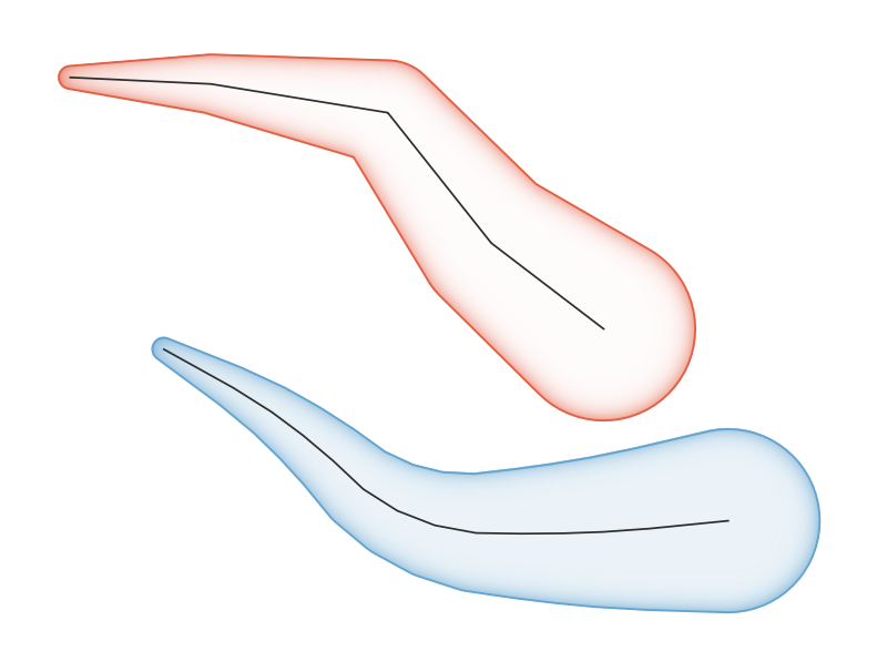
Tapered buffer example
Parameters
Label |
Name |
Type |
Description |
|---|---|---|---|
Input layer |
|
[vector: line] |
Input line vector layer |
Start width |
|
[number Default: 0.0 |
Represents the radius of the buffer applied at the start point of the line feature |
End width |
|
[number Default: 0.0 |
Represents the radius of the buffer applied at the end point of the line feature. |
Segments |
|
[number Default: 16 |
Controls the number of line segments to use to approximate a quarter circle when creating rounded offsets. |
Buffered |
|
[vector: polygon] Default: |
Specify the output (buffer) layer. One of:
The file encoding can also be changed here. |
Outputs
Label |
Name |
Type |
Description |
|---|---|---|---|
Buffered |
|
[vector: polygon] |
Output (buffer) polygon layer |
Tessellate
Tessellates a polygon geometry layer, dividing the geometries into triangular components.
The output layer consists of multipolygon geometries for each input feature, with each multipolygon consisting of multiple triangle component polygons.
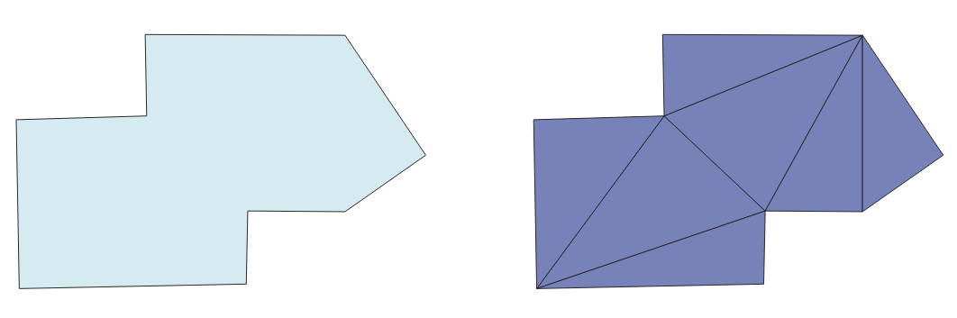
Tessellated polygon (right)
Allows
features in-place modification
Parameters
Label |
Name |
Type |
Description |
|---|---|---|---|
Input layer |
|
[vector: polygon] |
Input polygon vector layer |
Tesselated |
|
[vector: polygon] Default: |
Specify the output layer. One of:
The file encoding can also be changed here. |
Outputs
Label |
Name |
Type |
Description |
|---|---|---|---|
Tesselated |
|
[vector: polygon] |
Output multipolygonZ layer |
Transect
Creates transects on vertices for (multi)linestring.
A transect is a line oriented from an angle (by default perpendicular) to the input polylines (at vertices).
Field(s) from feature(s) are returned in the transect with these new fields:
TR_FID: ID of the original feature
TR_ID: ID of the transect. Each transect have an unique ID
TR_SEGMENT: ID of the segment of the linestring
TR_ANGLE: Angle in degrees from the original line at the vertex
TR_LENGTH: Total length of the transect returned
TR_ORIENT: Side of the transect (only on the left or right of the line, or both side)
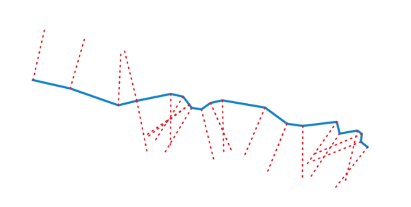
Dashed red lines represent the transect of the input line layer
Parameters
Label |
Name |
Type |
Description |
|---|---|---|---|
Input layer |
|
[vector: line] |
Input line vector layer |
Length of the transect |
|
[number Default: 5.0 |
Length in map unit of the transect |
Angle in degrees from the original line at the vertices |
|
[number Default: 90.0 |
Change the angle of the transect |
Side to create the transect |
|
[enumeration] |
Choose the side of the transect. Available options are:
|
Transect |
|
[vector: line] Default: |
Specify the output line layer. One of:
The file encoding can also be changed here. |
Outputs
Label |
Name |
Type |
Description |
|---|---|---|---|
Transect |
|
[vector: line] |
Output line layer |
Translate
Moves the geometries within a layer, by offsetting with a predefined X and Y displacement.
Z and M values present in the geometry can also be translated.
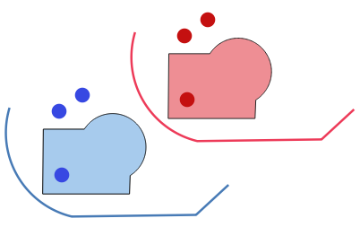
Dashed lines represent the translated geometry of the input layer
Allows
features in-place modification
Parameters
Label |
Name |
Type |
Description |
|---|---|---|---|
Input layer |
|
[vector: any] |
Input vector layer |
Offset distance (x-axis) |
|
[number Default: 0.0 |
Displacement to apply on the X axis |
Offset distance (y-axis) |
|
[number Default: 0.0 |
Displacement to apply on the Y axis |
Offset distance (z-axis) |
|
[number Default: 0.0 |
Displacement to apply on the Z axis |
Offset distance (m values) |
|
[number Default: 0.0 |
Displacement to apply on the M axis |
Translated |
|
[same as input] Default: |
Specify the output vector layer. One of:
The file encoding can also be changed here. |
Outputs
Label |
Name |
Type |
Description |
|---|---|---|---|
Translated |
|
[same as input] |
Output vector layer |
Variable distance buffer (Graphical Modeler only)
Computes a buffer area for all the features in an input layer. This algorithm is only available from the The graphical modeler.
The size of the buffer for a given feature is defined by an attribute, so it allows different features to have different buffer sizes.
See also
Parameters
Label |
Name |
Type |
Description |
|---|---|---|---|
Input layer |
|
[vector: any] |
Input vector layer |
Distance field |
|
[tablefield: numeric] |
Attribute for the distance radius of the buffer |
Segments |
|
[number] Default: 5 |
Controls the number of line segments to use to approximate a quarter circle when creating rounded offsets. |
Dissolve result |
|
[boolean] Default: False |
Choose to dissolve the final buffer, resulting in a single feature covering all input features.
Normal and dissolved buffer¶ |
End cap style |
|
[enumeration] |
Controls how line endings are handled in the buffer.
Round, flat and square cap styles¶ |
Join style |
|
[enumeration] |
Specifies whether round, miter or beveled joins should be used when offsetting corners in a line. |
Miter limit |
|
[number] Default: 2.0 |
Only applicable for mitered join styles, and controls the maximum distance from the offset curve to use when creating a mitered join. |
Outputs
Label |
Name |
Type |
Description |
|---|---|---|---|
Buffer |
|
[vector: polygon] |
Buffer polygon vector layer. |
Variable width buffer (by M value)
Creates variable width buffers along lines, using the M value of the line geometries as the diameter of the buffer at each vertex.
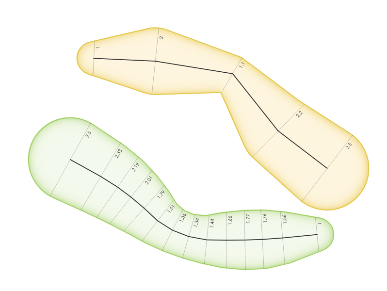
Variable buffer example
See also
Parameters
Label |
Name |
Type |
Description |
|---|---|---|---|
Input layer |
|
[vector: line] |
Input line vector layer |
Segments |
|
[number Default: 16 |
Number of the buffer segments per quarter circle. It can be a unique value (same value for all the features), or it can be taken from features data (the value can depend on feature attributes). |
Buffered |
|
[vector: polygon] Default: |
Specify the output (buffer) layer. One of:
The file encoding can also be changed here. |
Outputs
Label |
Name |
Type |
Description |
|---|---|---|---|
Buffered |
|
[vector: polygon] |
Variable buffer polygon layer |
Voronoi polygons
Takes a point layer and generates a polygon layer containing the Voronoi polygons (known also as Thiessen polygons) corresponding to those input points.
Any location within a Voronoi polygon is closer to the associated point than to any other point.
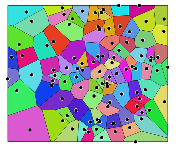
Voronoi polygons
Default menu:
Parameters
Label |
Name |
Type |
Description |
|---|---|---|---|
Input layer |
|
[vector: point] |
Input point vector layer |
Buffer region (% of extent) |
|
[number] Default: 0.0 |
The extent of the output layer will be this much bigger than the extent of the input layer |
Voronoi polygons |
|
[vector: polygon] Default: |
Specify the output layer (with the Voronoi polygons). One of:
The file encoding can also be changed here. |
Outputs
Label |
Name |
Type |
Description |
|---|---|---|---|
Voronoi polygons |
|
[vector: polygon] |
Voronoi polygons of the input point vector layer |