Importante
La traduzione è uno sforzo comunitario you can join. Questa pagina è attualmente tradotta al 41.18%.
17.26. L’interfaccia per i processi in serie
Nota
Questa lezione introduce l’interfaccia per i processi in serie, che permette di eseguire un singolo algoritmo con una serie di valori in ingresso differenti.
A volte un dato algoritmo deve essere eseguito ripetutamente con input diversi. Questo è, per esempio, il caso in cui un insieme di file di input deve essere convertito da un formato a un altro, o quando diversi layer in una data proiezione devono essere convertiti in un’altra proiezione.
In that case, calling the algorithm repeatedly on the toolbox is not the best option. Instead, the batch processing interface should be used, which greatly simplifies performing a multiple execution of a given algorithm. To run an algorithm as a batch process, find it in the toolbox, and instead of double-clicking on it, right-click on it and select Run as batch process.
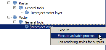
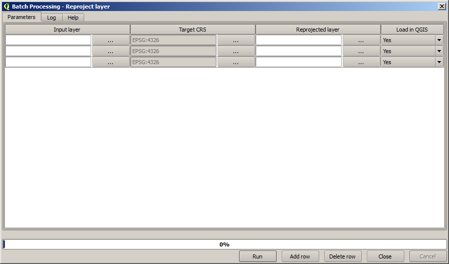
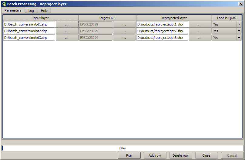
For this example, we will use the Reproject layer algorithm, so find it and do as described above. You will get to the following dialog.
Se dai un’occhiata ai dati per questa lezione, vedrai che contengono un insieme di tre shapefile, ma non il file di progetto QGIS. Questo perché, quando l’algoritmo è eseguito come un processo in serie, i vettori in ingresso possono essere selezionati o dal progetto QGIS corrente o dai file. Ciò rende più facile processare un grande quantitativo di vettori, come, per esempio, tutti i vettori in una data cartella.
Ogni riga nella tabella della finestra di dialogo per i processi in serie rappresenta una singola esecuzione dell’algoritmo. Le celle in ogni riga corrispondono ai parametri richiesti dall’algoritmo, i quali non sono disposti uno sopra l’altro, come nella tipica finestra di dialogo per una esecuzione singola, ma orizzontalmente lungo essa.
La definizione del processo in serie da eseguire si effettua riempiendo la tabella con i valori corrispondenti e la finestra di dialogo stessa contiene diversi strumenti che facilitano questo compito.
Let’s start filling the fields one by one. The first column to fill is the Input layer one. Instead of entering the names of each one of the layers we want to process, you can select all of them and let the dialog put one in each row. Click on the button in the upper-left cell, and in the file selection dialog that will popup, select the three files to reproject. Since only one of them is needed for each row, the remaining ones will be used to fill the rows underneath.
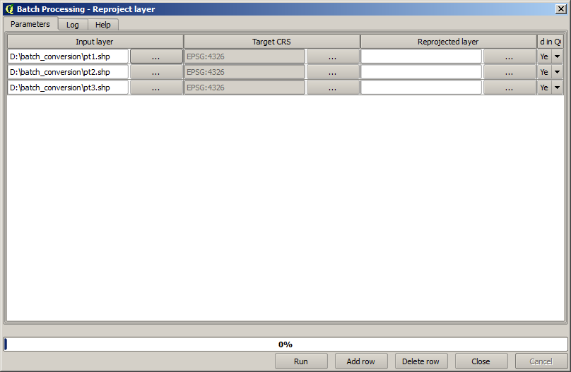
The default number of rows is 3, which is exactly the number of layers we have to convert, but if you select more layers, new rows will be added automatically. If you want to fill the entries manually, you can add more rows using the Add row button.
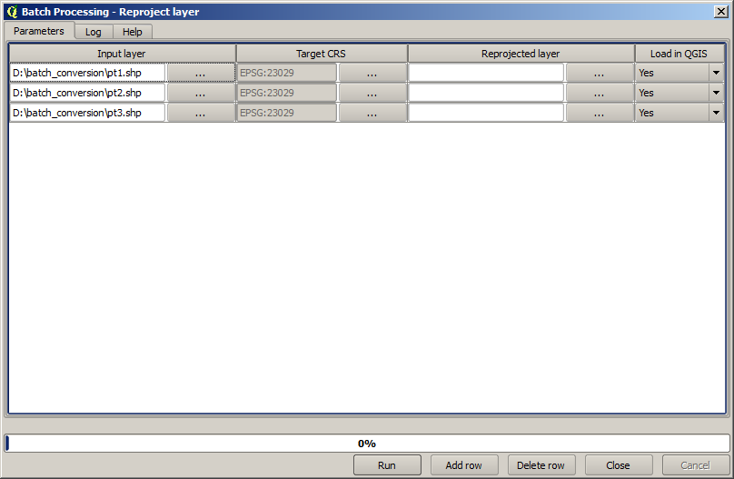
We are going to convert all those layers to the EPSG:23029 CRS, so we have to
select that CRS in the second field. We want the same on for all rows, but we
do not have to do it for every single row. Instead, set that CRS for the first
row (the one at the top) using the button in the corresponding cell, and then
double click on the column header. That causes all the cells in the column to
be filled using the value of the top cell.
Finally, we have to select an output file for each execution, which will contain
the corresponding reprojected layer. Once again, let’s do it just for the first row.
Click on the button in the upper cell and, in a folder where you want to put
your output files, enter a filename (for instance, reprojected.shp).
Now, when you click OK on the file selection dialog, the file does not automatically gets written to the cell, but an input box like the following one is shown instead.
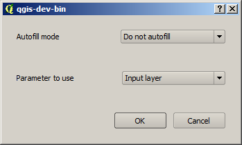
If you select the first option, only the current cell will be filled. If you
select any of the other ones, all the rows below will be filled with a given
pattern. In this case, we are going to select the Fill with parameter value
option, and then the Input Layer value in the drop down menu below.
That will cause the value in the Input Layer (that is, the layer name) to
be added to the filename we have added, making each output filename different.
The batch processing table should now look like this.
The last column sets whether or not to add the resulting layers to the
current QGIS project. Leave the default Yes option, so you can see your
results in this case.
Click on OK and the batch process will be run. If everything went fine, all your layers will have been processed, and 3 new layers would have been created.