` `
속성 테이블 작업
The attribute table displays information on features of a selected layer. Each row in the table represents a feature (with or without geometry), and each column contains a particular piece of information about the feature. Features in the table can be searched, selected, moved or even edited.
Foreword: Spatial and non-spatial tables
QGIS allows you to load spatial and non-spatial layers. This currently includes tables supported by OGR and delimited text, as well as the PostgreSQL, MSSQL, SpatiaLite, DB2 and Oracle provider. All loaded layers are listed in the Layers Panel. Whether a layer is spatially enabled or not determines whether you can interact with it on the map.
Non-spatial tables can be browsed and edited using the attribute table view. Furthermore, they can be used for field lookups. For example, you can use columns of a non-spatial table to define attribute values, or a range of values that are allowed, to be added to a specific vector layer during digitizing. Have a closer look at the edit widget in section Fields Properties to find out more.
Introducing the attribute table interface
To open the attribute table for a vector layer, activate the layer by
clicking on it in the 레이어 패널. Then, from the main
Layer menu, choose  Open Attribute
Table. It is also possible to right-click on the layer and choose
Open Attribute Table from the drop-down menu,
or to click on the Open Attribute Table button
in the Attributes toolbar.
Open Attribute
Table. It is also possible to right-click on the layer and choose
Open Attribute Table from the drop-down menu,
or to click on the Open Attribute Table button
in the Attributes toolbar.
This will open a new window that displays the feature attributes for the layer (figure_attributes_table). According to the setting in Settings ‣ Options ‣ Data sources menu, the attribute table will open in a docked window or a regular window. The total number of features in the layer and the number of currently selected/filtered features are shown in the attribute table title, as well as if the layer is spatially limited.
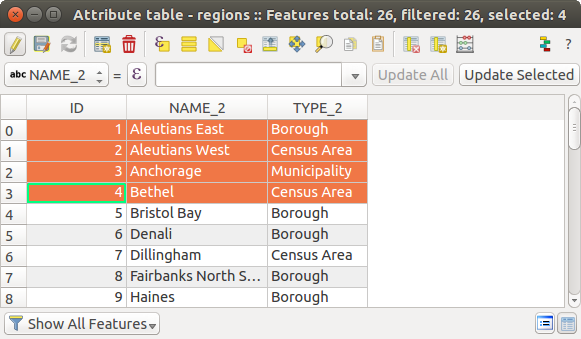
“regions” 레이어의 속성 테이블
속성 테이블 창 상단에 있는 아이콘들은 다음과 같은 기능을 제공합니다:
아이콘 |
라벨 |
목적 |
기본 단축키 |
|---|---|---|---|
 |
Toggle editing mode | 편집 기능 활성화 |
Ctrl+E |
 |
Toggle multi edit mode | 여러 피처들의 여러 필드들을 업데이트 |
|
 |
Save Edits | 현재 수정 사항을 저장 |
Ctrl+S |
 |
Reload the table | ||
 |
Add feature | 도형 없는 새 피처를 추가 |
|
 |
Delete selected features | 레이어에서 선택한 피처를 제거 |
|
 |
Select features using an Expression | ||
 |
Select All | 레이어에 있는 모든 피처를 선택 |
Ctrl+A |
 |
Invert selection | 레이어에 있는 현재 선택을 반전 |
Ctrl+R |
 |
Deselect all | 현재 레이어에 있는 모든 피처를 선택 해제 |
Ctrl+Shift+A |
 |
양식을 이용해서 피처 필터링/선택하기 |
Ctrl+F | |
 |
Move selected to top | 선택한 행을 테이블 맨 위로 이동 |
|
 |
Pan map to the selected rows | Ctrl+P | |
 |
Zoom map to the selected rows | Ctrl+J | |
 |
Copy selected rows to clipboard | Ctrl+C | |
 |
Paste features from clipboard | 복사한 피처로부터 새 피처를 삽입 |
Ctrl+V |
 |
New field | 데이터소스에 새 필드를 추가 |
Ctrl+W |
 |
Delete field | 데이터소스에서 필드를 제거 |
Ctrl+L |
 |
Open field calculator | 행에 있는 여러 피처들의 필드를 업데이트 |
Ctrl+I |
 |
Conditional formatting | 테이블 서식 작업 활성화 |
표 속성 1: 사용할 수 있는 도구들
주석
데이터 유형 및 사용자의 QGIS 버전과 함께 빌드한 OGR 라이브러리에 따라, 일부 도구를 사용하지 못 할 수도 있습니다.
이 아이콘들 아래엔 (편집 모드 일 때만 활성화되는) 간편 필드 계산 막대가 있는데, 이 계산 막대를 통해 레이어에 있는 피처들 전부 또는 일부에 계산을 간편하게 적용할 수 있습니다. 이 막대는 Field Calculator (속성값 편집 참조)와 동일한 표현식 을 이용합니다.
참고
Skip WKT geometry
If you want to use attribute data in external programs (such as Excel), use the
Copy selected rows to clipboard button.
You can copy the information without vector geometries if you deactivate the
 Copy geometry in WKT representation from attribute table
option in Settings ‣ Options ‣ Data Sources menu.
Copy geometry in WKT representation from attribute table
option in Settings ‣ Options ‣ Data Sources menu.
테이블 뷰 대 양식 뷰
QGIS는 속성 테이블에서 데이터를 쉽게 수정할 수 있는 뷰 모드 2개를 제공하고 있습니다:
- the Table view, displaying values of multiple features in a
tabular mode, each row representing a feature and each column a field;
- and the
 Form view which shows identifiers of features in a first
panel and displays only the attributes of the clicked identifier in the second
one. Form view uses the layer fields configuration
(see Fields Properties).
Form view which shows identifiers of features in a first
panel and displays only the attributes of the clicked identifier in the second
one. Form view uses the layer fields configuration
(see Fields Properties).
You can switch from one mode to the other by clicking the convenient icon at the bottom right of the dialog.
Settings ‣ Options ‣ Data Sources 메뉴에서 속성 테이블이 열릴 때의 Default view 를 설정할 수도 있습니다. ‘Remember last view’, ‘Table view’ 또는 ‘Form view’ 옵션 가운데 하나를 선택할 수 있습니다.
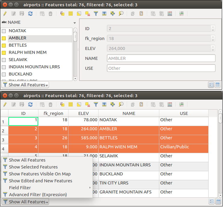
속성 테이블의 양식 뷰(위) 대 테이블 뷰(아래)
Configuring the columns
테이블 뷰의 경우, 속성 테이블에 무엇을 어떻게 표시할지에 대한 환경을 설정할 수 있는 도구에 접근하려면 열 헤더를 오른쪽 클릭하십시오.
Hiding and organizing columns and enabling actions
열 헤더를 오른쪽 클릭하면, 속성 테이블에서 열을 숨기는 옵션을 선택할 수 있습니다. 열을 숨김 해제하거나 열의 순서를 변경하는 등 한 번에 여러 열들의 습성을 변경하려면, Organize columns ... 메뉴 옵션을 선택하십시오. 새 대화창에서 다음 작업을 할 수 있습니다:
표시하거나 숨기려하는 열을 체크/체크 해제할 수 있습니다.
속성 테이블에서 열을 재정렬하기 위해 항목을 드래그&드롭할 수 있습니다. 이 작업은 테이블 렌더링을 변경하는 것이지 레이어 데이터소스의 필드 순서를 변경하는 것이 아니라는 점을 기억하십시오.
각 행에 액션의 드롭다운 상자 또는 버튼 목록을 표시하는 새로운 가상 Actions 열을 활성화할 수 있습니다. 액션에 관한 자세한 정보는 액션 속성 을 참조하세요.
Resizing columns widths
열 헤더를 오른쪽 클릭한 다음 다음 가운데 하나를 선택하면 열 너비를 설정할 수 있습니다:
Set width...: 원하는 값을 입력할 수 있습니다. 기본적으로, 위젯에는 현재 값이 표시됩니다.
Autosize: 열에 가장 알맞은 너비로 조정할 수 있습니다.
열 헤더의 오른쪽 경계선을 드래그해도 너비를 변경할 수 있습니다. 레이어는 열의 새로운 크기를 유지하기 때문에, 다음에 속성 테이블을 열어도 변경한 너비가 복구됩니다.
Sorting columns
열 헤더를 클릭하면 어느 열 기준으로도 테이블을 정렬할 수 있습니다. 작은 화살표가 정렬 순서를 나타냅니다. (아래쪽 화살표는 맨 위 행에서 아래 행 방향으로 내림차순, 위쪽 화살표는 맨 위 행에서 아래 행 방향으로 오름차순을 의미합니다.) 열 헤더 컨텍스트 메뉴의 Sort 옵션을 선택한 다음 표현식을 입력해서 행들을 정렬하도록 선택할 수도 있습니다. 예를 들어 여러 열을 이용해서 행을 정렬하려면 concat(col0, col1) 같은 표현식을 작성하면 됩니다.
양식 뷰에서는,  Sort by preview expression 옵션을 통해 피처 식별자를 정렬할 수 있습니다.
참고
Sorting based on columns of different types
Trying to sort an attribute table based on columns of string and numeric types may lead to unexpected result because of the concat("USE", "ID") expression returning string values (ie, 'Borough105' < 'Borough6'). You can workaround this by using eg concat("USE", lpad("ID", 3, 0)) which returns 'Borough105' > 'Borough006'.
Formatting of table cells using conditions
Conditional formatting settings can be used to highlight in the attribute table features you may want to put a particular focus on, using custom conditions on feature’s:
도형 (예를 들어 다중 부분 피처, 작은 면적을 가진 피처, 또는 지정한 맵 범위 안에 있는 피처 등등)
- or field value (e.g., comparing values to a threshold, identifying empty cells...)
테이블 뷰의 (양식 뷰에서는 사용할 수 없습니다) 속성 창 우상단에 있는 아이콘을 클릭하면 조건부 서식 패널을 활성화할 수 있습니다.
이 새 패널에서  Field 또는
  Full row 의 서식을 렌더링하기 위한 새 규칙을 추가할 수 있습니다. 새 규칙을 추가하는 양식이 열리는데, 다음 항목을 정의할 수 있습니다:
규칙의 명칭
표현식 작성기 함수를 이용한 조건
서식: 사전 정의된 서식 목록에서 선택하거나, 다음과 같은 속성을 기반으로 생성할 수도 있습니다:
배경 및 텍스트 색상
아이콘 사용 여부
볼드체, 이탤릭체, 밑줄, 취소선
폰트
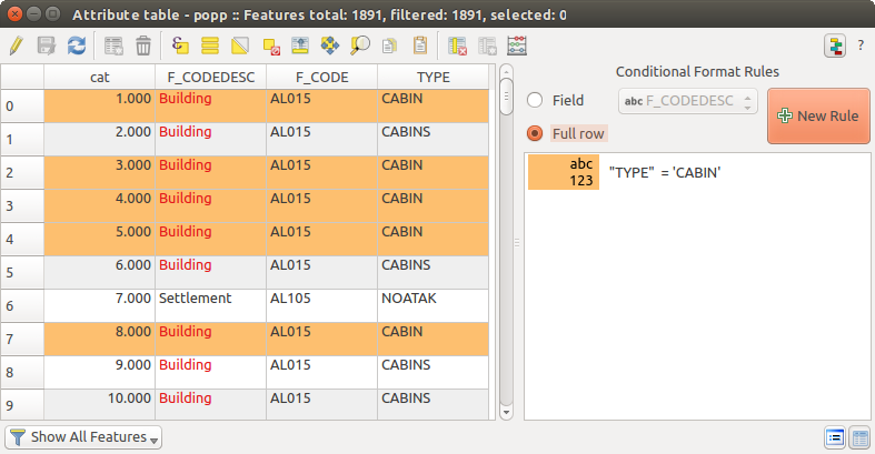
속성 테이블의 조건부 서식
속성 테이블의 피처와 상호작용
피처 선택
테이블 뷰에서, 속성 테이블의 각 행은 레이어에 있는 유일 피처의 속성들을 표시합니다. 행을 선택하면 피처도 선택되며 마찬가지로 맵 캔버스에서 (도형을 사용할 수 있는 레이어인 경우) 피처를 선택하면 속성 테이블에서 해당 행이 선택됩니다. 맵 캔버스(또는 속성 테이블)에서 선택한 피처의 집합을 변경하는 경우, 그에 따라 속성 테이블(또는 맵 캔버스)에 있는 선택도 업데이트됩니다.
행 왼쪽에 있는 행 번호를 클릭하면 행을 선택할 수 있습니다. Ctrl 키를 누른채 클릭하면 여러 행들 을 선택 표시할 수 있습니다. Shift 키를 누른 채 행 왼쪽에 있는 행 헤더를 몇 개 클릭하면 연속 선택 을 할 수 있습니다. 현재 커서 위치와 클릭한 행 사이의 모든 행들이 선택될 것입니다. 테이블에 있는 셀을 클릭해서 속성 테이블에서 커서 위치를 이동해도 행 선택이 변경되지는 않습니다. 맵 캔버스에서 선택을 변경해도 속성 테이블에서 커서 위치가 이동되지 않습니다.
속성 테이블의 양식 뷰에서는, 기본적으로 왼쪽 패널에 표시된 필드의 값으로 (표시 속성 참조) 피처를 식별합니다. 패널 상단에 있는 드롭다운 목록을 통해 기존 필드를 선택하거나 또는 사용자 지정 표현식을 이용해서 이 식별자를 대체할 수 있습니다. 컨텍스트 메뉴에서 피처 목록을 정렬하도록 선택할 수도 있습니다.
오른쪽 패널에 피처의 속성을 표시하려면 왼쪽 패널에 있는 값을 클릭하십시오. 피처를 선택하려면, 식별자 왼쪽에 있는 정사각형 심볼 안을 클릭해야 합니다. 기본적으로, 심볼이 노랑색으로 바뀔 겁니다. 테이블 뷰와 마찬가지로, 앞에서 설명한 대로 조합키를 이용해서 여러 피처를 한꺼번에 선택할 수 있습니다.
마우스로 피처를 선택하는 것 외에도, 속성 테이블 툴바에서 다음과 같은 툴을 이용해서 피처의 속성에 기반한 자동 선택을 할 수 있습니다(더 자세한 정보와 용례를 알고 싶다면 자동 선택 항 및 그 다음 항을 참조하세요):
- Select By Expression...
 Select Features By Value...
- Deselect Features from All Layers
- Select All Features
- Invert Feature Selection
Filtering and selecting features using forms 를 이용해서 피처를 선택할 수도 있습니다.
피처 필터링
속성 테이블에서 피처를 선택하고 나면, 테이블에 선택한 레코드만 표시하기를 바랄 수도 있습니다. 속성 테이블 대화창 좌하단에 있는 드롭다운 목록에서 Show Selected Features 항목을 선택하면 간단하게 선택한 레코드만 볼 수 있습니다. 이 목록은 다음과 같은 필터를 제공하고 있습니다:
- Show All Features
- Show Selected Features
- Show Features visible on map
- Show Edited and New Features
Field Filter: 필드의 값을 기반으로 필터링할 수 있습니다. 목록에서 열을 선택해서 값을 입력한 다음 Enter 키를 눌러 필터링합니다. 그러면 속성 테이블에 일치하는 피처만 표시될 것입니다.
- Advanced filter (Expression) - Opens the expression builder dialog. Within it, you can create complex expressions to match table rows. For example, you can filter the table using more that one field. See 표현식 for more information.
Filtering and selecting features using forms 를 통해 피처를 필터링할 수도 있습니다.
주석
속성 테이블에서 레코드를 필터링해도 레이어에서 피처를 필터링하지는 않습니다. 일시적으로 테이블에서 숨겨진 것뿐으로, 맵 캔버스에서 접근할 수도 있고 필터를 제거해서 접근할 수도 있습니다. 레이어에서 피처를 실제로 숨기는 필터를 원한다면, 쿼리 작성기 를 이용하십시오.
참고
Show Features Visible on Map 으로 데이터소스 필터링 업데이트
성능 향상을 목적으로, 속성 대화창이 열릴 때 속성 테이블에 표시되는 피처가 공간적으로 맵 캔버스 범위로 제한돼 있는 경우 (이 방법에 대해서는 데이터소스 옵션 을 참조하세요) 새 캔버스 범위 상에서 Show Features Visible on Map 을 선택하면 공간 제약 조건을 업데이트합니다.
Filtering and selecting features using forms
Filter/Select features using form 을 클릭하거나 Ctrl+F 조합키를 누르면 속성 테이블 대화창이 양식 뷰로 전환되고 모든 위젯도 해당 위젯의 검색형으로 대체될 것입니다.
이 다음부터 설명할 도구 기능은 값으로 피처 선택 항에서 설명한 것과 유사합니다. 이 항에서 모든 연산자 및 선택 모드에 대한 설명을 찾아볼 수 있습니다.
여기에 더해 속성 테이블의 경우, 피처를 선택하는 대신 (사용자 고유의 고급 필터(표현식)를 생성해서) 필터링할 수 있는 Filter features 버튼도 존재합니다.
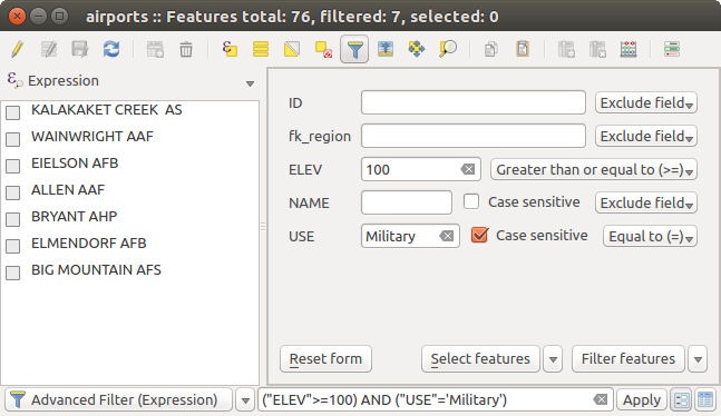
필터 양식으로 필터링한 속성 테이블
이미 필터링한 피처가 있는 경우, Filter features 버튼 옆에 있는 드롭다운 목록을 이용해서 필터를 미세 조정할 수 있습니다. 다음 옵션을 선택할 수 있습니다:
- Filter within (“AND”)
- Extend filter (“OR”)
To clear the filter, either select Show all features option mentioned in 피처 필터링, or click the clear the expression and click [Apply].
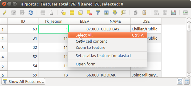
Using action on features
컨텍스트 메뉴를 통해 피처를 다음과 같이 처리할 수 있습니다:
- Select all (Ctrl+A) the features
- Copy the content of a cell in the clipboard with Copy cell content.
- Zoom to feature without having to select it beforehand
- Open form. It toggles attribute table into form view with a focus on the clicked feature
셀 내용 복사 버튼
외부 프로그램에서 (예: 엑셀, 리브레오피스, QGIS 또는 사용자 지정 웹 응용 프로그램 등) 속성 데이터를 이용하고 싶은 경우, 하나 또는 그 이상의 행(들)을 선택한 다음 Copy selected rows to clipboard 아이콘을 클릭하거나 Ctrl+C 조합키를 누르십시오.
Settings ‣ Options ‣ Data Sources 메뉴에서 Copy features as 드롭다운 목록을 통해 붙여넣을 포맷을 다음 가운데 정의할 수 있습니다:
평문 텍스트, 도형 없음
평문 텍스트, WKT 도형
- GeoJSON
이 컨텍스트 메뉴에 액션 목록을 표시할 수도 있습니다. Layer properties ‣ Actions 탭에서 활성화할 수 있습니다. 액션에 관한 자세한 정보는 액션 속성 을 참조하세요.
Saving selected features as new layer
The selected features can be saved as any OGR-supported vector format and
also transformed into another coordinate reference system (CRS). In the
contextual menu of the layer, from the Layers Panel, click on
Save as to define the name of the output file, its format
and CRS (see section Creating new layers from an existing layer). To save the selection ensure
that the Save only selected features is selected.
It is also possible to specify OGR creation options within the dialog.
속성값 편집
다음과 같은 방법으로 속성값을 편집할 수 있습니다:
셀 안에 새 값을 직접 입력합니다. 속성 테이블이 테이블 뷰 모드인지 양식 뷰 모드인지는 상관없습니다. 셀 별로, 피처 별로 변경할 수 있습니다.
- using the field calculator: update in a row a field that may already exist or to be created but for multiple features; it can be used to create virtual fields.
- using the quick field calculation bar: same as above but for only existing field
다중 편집 모드를 이용합니다. 행에서 여러 피처의 여러 필드를 업데이트합니다.
Using the Field Calculator
The Field Calculator button in the attribute table
allows you to perform calculations on the basis of existing attribute values or
defined functions, for instance, to calculate length or area of geometry
features. The results can be written to a new attribute field, a virtual field,
or they can be used to update values in an existing field.
편집을 지원하는 레이어라면 필드 계산기를 사용할 수 있습니다. 필드 계산기 아이콘을 클릭하면 대화창이 열립니다. (필드 계산기 그림 참조) 레이어가 편집 모드가 아닌 경우, 필드 계산기가 계산을 하기 전에 경고 메시지를 표시한 다음 레이어를 편집 모드로 전환할 것입니다.
Based on the Expression Builder dialog, the field calculator dialog offers a complete interface to define an expression and apply it to an existing or a newly created field. To use the field calculator dialog, you first must select whether you want to only update selected features, create a new attribute field where the results of the calculation will be added or update an existing field.
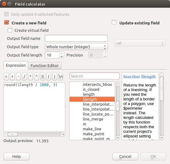
필드 계산기
If you choose to add a new field, you need to enter a field name, a field type (integer, real, date or string) and if needed, the total field length and the field precision. For example, if you choose a field length of 10 and a field precision of 3, it means you have 6 digits before the dot, then the dot and another 3 digits for the precision.
다음은 Expression 탭을 이용하는 경우 필드 계산기가 어떻게 작동하는지 보여주는 짧은 예시입니다. QGIS 예시 데이터셋의 railroads 레이어의 길이를 킬로미터 단위로 계산하려 합니다:
QGIS에 railroads.shp shapefile을 불러온 다음
Open Attribute Table 아이콘을 클릭합니다.- Toggle editing mode 아이콘을 클릭한 다음 Field Calculator 아이콘으로 필드 계산기 대화창을 엽니다.
- Create a new field 체크박스를 체크해서 계산 결과를 새로운 필드로 저장하도록 합니다.
산출 필드명을 length 로, 산출 필드 유형을 real 로, 그리고 산출 필드 길이를 10으로, 정밀도를 3으로 입력합니다.
이제 Geometry 그룹에 있는 $length 함수를 더블클릭해서 필드 계산기의 표현식 란에 추가합니다.
- Complete the expression by typing / 1000 in the Field calculator expression box and click [Ok].
이제 속성 테이블에서 새 필드 length 를 찾아볼 수 있습니다.
Creating a Virtual Field
A virtual field is a field based on an expression calculated on the fly, meaning that its value is automatically updated as soon as the underlying parameter changes. The expression is set once; you no longer need to recalculate the field each time underlying values change. For example, you may want to use a virtual field if you need area to be evaluated as you digitize features or to automatically calculate a duration between dates that may change (e.g., using now() function).
주석
가상 필드 사용법
가상 필드는 레이어 속성에 영구히 유지되지 않습니다. 가상 필드가 생성된 프로젝트의 프로젝트 파일에만 저장되고 사용할 수 있다는 뜻입니다.
필드 생성 시에만 가상 필드로 설정할 수 있고, 사용된 표현식을 이후 변경할 수 없습니다. 표현식을 변경하려면 해당 필드를 삭제한 다음 다시 생성해야 합니다.
Using the Quick Field Calculation Bar
While Field calculator is always available, the quick field calculation bar on top of the attribute table is only visible if the layer is in edit mode. Thanks to the expression engine, it offers a quicker access to edit an already existing field.
In quick field calculation bar, you simply need to:
- select the existing field name in the drop-down list
- fill the textbox with an expression you directly write or build using the
 expression button
 - and click on [Update All], [Update Selected] or [Update Filtered] button according to your need.
Editing multiple fields
이전 도구들과는 달리, 다중 편집 모드는 동시에 서로 다른 피처들의 여러 속성들을 편집할 수 있습니다. 레이어가 편집 모드로 전환되면, 다음과 같이 다중 편집 기능에 접근할 수 있습니다:
- using the Toggle multi edit mode button from the toolbar
inside the attribute table dialog,
Edit ‣
Modify attributes of selected features 메뉴를 선택합니다.
행에서 여러 필드를 편집하려면:
select the features you want to edit;
from the attribute table toolbar, click the
button. This will
toggle the dialog to its form view. Feature selection could also be made
at this step;at the right side of the attribute table, fields (and values) of selected features are shown. New widgets appear next to each field allowing for display of the current multi edit state:
 the field contains different values for selected
features. It’s shown empty and each feature will keep its original value.
You can reset the value of the field from the drop-down list of the widget.
the field contains different values for selected
features. It’s shown empty and each feature will keep its original value.
You can reset the value of the field from the drop-down list of the widget. all selected features have the same value for this
field and the value displayed in the form will be kept.
all selected features have the same value for this
field and the value displayed in the form will be kept. the field has been edited and the entered value
will be applied to all the selected features. A message appears at the top
of the dialog, inviting you to either apply or reset your modification.
the field has been edited and the entered value
will be applied to all the selected features. A message appears at the top
of the dialog, inviting you to either apply or reset your modification.
이 위젯 가운데 하나를 클릭하면 필드 별로 현재 값을 설정하거나 원본 값으로 리셋할 수 있습니다. 즉 필드 별로 사용자 변경 사항을 되돌릴 수 있다는 뜻입니다.
make the changes to the fields you want and click on Apply changes in the upper message text or any other feature in the left panel.
선택한 모든 피처 에 변경 사항을 적용할 것입니다. 선택한 피처가 없는 경우, 전체 테이블을 사용자 변경 사항으로 업데이트합니다. 수정 작업은 단일 편집 명령어로 이루어집니다. 따라서  Undo 아이콘을 클릭하면 선택한 모든 피처의 속성 변경 사항을 한 번에 되돌릴 것입니다.
주석
속성 테이블에 있는 도구와는 달리, Edit ‣ Modify Attributes of Selected Features 메뉴 옵션을 선택하면 속성 변경 사항을 입력할 수 있는 모달 대화창이 열립니다. 즉, 실행 전에 피처를 선택해놓아야 합니다.
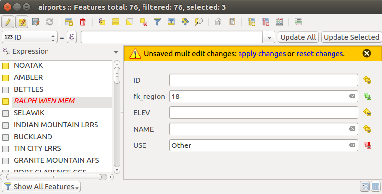
여러 피처의 필드들을 편집하기
주석
다중 편집 모드는 자동 생성된 드래그&드롭 양식에서만 사용할 수 있습니다. (Customize a form for your data 을 참조하세요.) 사용자 UI 양식은 지원하지 않습니다.
일대다 또는 다대다 관계 생성
관계는 데이터베이스에서 자주 이용되는 기술입니다. 관계란 서로 다른 레이어(테이블)의 피처(행)가 서로에게 속할 수 있다는 개념입니다.
Introducing 1-N relations
예를 들어 사용자에게 알래스카의 모든 지역을 담고 있고, 지역명, 지역 유형, (기본키로 동작하는) 유일 ID 관련 속성을 제공하는 (폴리곤) 레이어가 있다고 해보겠습니다.
그런데 알래스카 지역에 위치한 공항 관련 정보를 담고 있는 또다른 포인트 레이어 또는 테이블을 얻었고, 사용자가 이 공항들도 파악하고 싶다고 해보겠습니다. regions 레이어에 이 공항들을 추가하려면, 외래 키(foreign key)를 이용해서 일대다 관계를 생성해야 합니다. 왜냐하면 대부분의 지역에 공항이 몇 군데씩 있기 때문입니다.
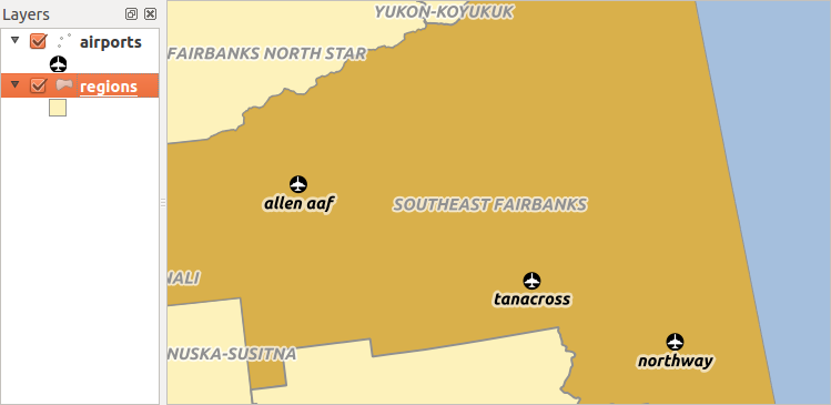
알래스카의 지역과 공항
Layers in 1-N relations
QGIS는 테이블과 벡터 레이어를 전혀 구분하지 않습니다. 기본적으로, 벡터 레이어는 도형을 지닌 테이블입니다. 따라서 사용자의 테이블을 벡터 레이어로 추가할 수 있습니다. 일대다 관계를 시연해보기 위해, regions shapefile과 regions 레이어에 대한 외래 키 필드(fk_region)를 가지고 있는 airports shapefile을 불러오겠습니다. 이 말은 각 공항이 딱 1개 지역에만 속해 있는 반면 각 지역은 공항을 몇 개든 가지고 있을 수 있다는 뜻입니다. (전형적인 일대다 관계죠.)
Foreign keys in 1-N relations
airports 레이어의 속성 테이블에 있는 기존 속성 이외에, 외래 키로 동작하는 또다른 fk_region 필드가 필요할 겁니다. (데이터베이스를 사용하고 있다면, 외래 키에 제약 조건을 정의해두는 편이 좋습니다.)
이 fk_region 필드는 항상 지역의 ID를 담고 있습니다. ID가 속한 지역을 가리키는 포인터라고 생각할 수도 있습니다. 그리고 편집 작업을 위한 사용자 지정 편집기를 디자인할 수 있으며, QGIS가 설정을 처리할 겁니다. 서로 다른 제공자들과 작동하며 (따라서 shapefile 및 CSV 파일도 사용할 수 있습니다) 사용자가 해야 할 일은 QGIS에 사용자의 두 테이블 간의 관계를 알려주는 것뿐입니다.
Defining 1-N relations (Relation Manager)
The first thing we are going to do is to let QGIS know about the relations between the layers. This is done in Project ‣ Project Properties.... Open the Relations tab and click on [Add Relation].
- name is going to be used as a title. It should be a human readable string, describing, what the relation is used for. We will just call say Airports in this case.
- referencing layer also considered as child layer, is the one with the foreign key field on it. In our case, this is the airports layer
- referencing field will say, which field points to the other layer so this is fk_region in this case
- referenced layer also considered as parent layer, is the one with the primary key, pointed to, so here it is the regions layer
- referenced field is the primary key of the referenced layer so it is ID
- id will be used for internal purposes and has to be unique. You may need it to build custom forms. If you leave it empty, one will be generated for you but you can assign one yourself to get one that is easier to handle.
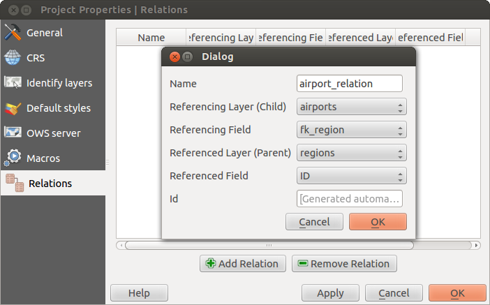
관계 관리자
Forms for 1-N relations
이제 QGIS가 관계를 인지했으니, 관계를 이용해서 QGIS가 생성하는 양식을 향상시킬 것입니다. 기본 양식 생성 방법(자동 생성)을 변경하지 않았으므로, 양식에 위젯 하나만 추가할 것입니다. 범례에서 regions 레이어를 선택한 다음 식별 도구를 써보십시오. 사용자 설정에 따라 양식이 바로 열릴 수도 있고, 식별 대화창의 액션을 통해 양식을 열어야 할 수도 있습니다.
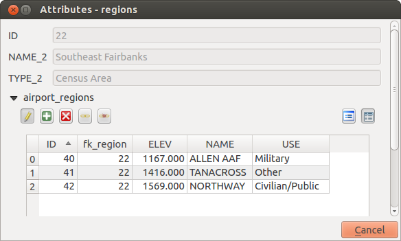
“airports”와 관계가 생성된 “regions”의 식별 대화창
As you can see, the airports assigned to this particular region are all shown in a table. And there are also some buttons available. Let’s review them shortly
- 아이콘은 편집 모드를 켜고 끕니다. 현재 regions 레이어에 있는 피처의 피처 양식을 보고 있긴 하지만, 이 아이콘은 airports 레이어의 편집 모드를 켜고 끈다는 점을 조심하십시오. 왜냐하면 테이블이 airports 레이어의 피처를 표시하고 있기 때문입니다.
- The
 button will add a new feature to the airport layer. And it will
assign the new airport to the current region by default.
button will add a new feature to the airport layer. And it will
assign the new airport to the current region by default. - The
 button will delete the selected airport permanently.
  아이콘은 기존의 어떤 공항이라도 선택해서 현재 지역에 할당시킬 수 있는 새 대화창을 엽니다. 사용자가 잘못된 지역에 공항을 실수로 생성한 경우 이 기능이 유용할 겁니다.
 아이콘은 현재 지역에서 선택한 공항을 할당 해제시켜, 사실상 비할당 상태로 (외래 키가 NULL로 설정된 상태로) 남겨둡니다.
- The two buttons to the right switch between table view and form view where the later let’s you view all the airports in their respective form.
If you work on the airport table, a new widget type is available which lets you embed the feature form of the referenced region on the feature form of the airports. It can be used when you open the layer properties of the airports table, switch to the Fields menu and change the widget type of the foreign key field ‘fk_region’ to Relation Reference.
지금 피처 대화창을 보고 있다면, 지역의 양식이 공항 양식 안에 삽입돼 있고 현재 공항을 다른 지역으로 할당할 수 있는 콤보박스도 있다는 것을 알 수 있을 겁니다.
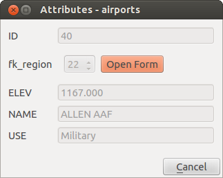
“regions”와 관계가 생성된 “airports”의 식별 대화창
Introducing many-to-many (N-M) relations
N-M relations are many-to-many relation between two tables. For instance, the airports and airlines layers: an airport receives several airline companies and an airline company flies to several airports.
In such case, we need a pivot table to list all airlines for all airports. In QGIS, you should setup two one-to-many relations as explained above:
airlines 테이블과 피벗 테이블 간의 관계
airports 테이블과 피벗 테이블 간의 두 번째 관계
When we add a new child (i.e. a company to an airport), QGIS will add a new row in the pivot table and in the airlines table. If we link a company to an airport, QGIS will only add a row in the pivot table.
In case you want to remove a link, an airline or an airport, QGIS won’t remove the row in the pivot table. The database administrator should add a ON DELETE CASCADE instruction in the foreign key constraint:
ALTER TABLE location.airlines
ADD CONSTRAINT location_airlines_airports_id_fkey
   FOREIGN KEY (id)
      REFERENCES location.airports(id)
         ON DELETE CASCADE;
주석
Combining N-M relation with automatic transaction group
이런 맥락에서 작업하는 경우 Project Properties ‣ Data Sources ‣ 메뉴 옵션에서 트랜잭션 모드를 활성화시켜야 합니다. QGIS가 모든 테이블(airlines, airports 및 피벗 테이블)에 있는 행(들)을 추가하거나 업데이트할 수 있어야 하기 때문입니다.
Finally, adding such relations in a form is done in the same way that for a one-to-many relation. The Relations panel in the Fields properties of the vector layer will let the user add the relation in the form. It will appear as a Many to many relation.