Importante
A tradução é um esforço comunitário você pode contribuir. Esta página está atualmente traduzida em 48.43%.
12.3. Editando
QGIS has various capabilities for editing OGR, SpatiaLite, PostgreSQL, MS SQL Server and Oracle Spatial vector layers and tables. They can be of 2D or 3D geometry type.
Nota
O procedimento para editar camadas do GRASS é diferente - consulte a seção Digitalizando e editando uma camada vetorial GRASS para mais detalhes.
Atenção
Edições Simultâneas
QGIS does not track if somebody else is editing the same feature at the same time as you are. The last person to save the edits wins.
Dica
Validando Edições
Continuous validation can be activated on a layer basis in the tab. More at Propriedades de Digitalização.
12.3.1. Setting the snapping tolerance and search radius
Under the menu, QGIS provides a number of parameters to configure default behaviour of editing tools. More information at Definições de digitalização.
For optimal and accurate editing of vector layer geometries, we need to set an appropriate value of snapping tolerance and search radius for features vertices. The Snapping group provides related options, namely handling of the snapping tolerance and the search radius.
Snapping tolerance: When you add a new vertex or move an existing one, the snapping tolerance is the distance QGIS uses to search for the closest vertex or segment you are trying to connect to. If you are not within the snapping tolerance, QGIS will leave the vertex where you release the mouse button, instead of snapping it to an existing vertex or segment.
The tolerance setting affects all tools that work with snapping and applies by default to new layers and projects. It can however be overridden at layer level (see Snapping and Digitizing Options).
Search radius: Search radius for vertex edits is the distance QGIS uses to
searchfor the vertex to select when you click on the map. If you are not within the search radius, QGIS will not find and select any vertex for editing.
A tolerância ao snap e o raio de pesquisa são definidos em `` unidades de mapa`` ou `` pixels``. Pode ser necessário experimentar para acertar. Se você especificar uma tolerância muito grande, o QGIS poderá se ajustar ao vértice errado, especialmente se você estiver lidando com um grande número de vértices nas proximidades. Quanto menor o raio de pesquisa, mais difícil será atingir o que você deseja mover.
12.3.2. Snapping and Digitizing Options
Global snapping and digitizing settings (snapping mode, tolerance value, and units…) can be overridden in the project from the menu. In the Snapping and Digitizing Options, you can also configure some other properties (snapping layers, scale limit, topology…) The Snapping Toolbar gives access to most of these features.
By default, snapping is disabled in a project until you press the
 Enable snapping button or press S.
The snapping mode, tolerance value, and units can also be configured in
this toolbar.
Enable snapping button or press S.
The snapping mode, tolerance value, and units can also be configured in
this toolbar.
12.3.2.1. Snapping properties
Existem três opções para selecionar as camadas nas quais ajustar:
: guilabel: Todas as camadas: configuração rápida para todas as camadas visíveis no projeto, para que o ponteiro se encaixe em todos os vértices e / ou segmentos. Na maioria dos casos, é suficiente usar esse modo de ajuste, mas tenha cuidado ao usá-lo em projetos com muitas camadas de vetores, pois isso pode afetar o desempenho.
: guilabel: Camada atual: somente a camada ativa é usada, uma maneira conveniente de garantir consistência topológica na camada que está sendo editada.
Advanced Configuration: allows you to enable and adjust snapping mode, tolerance and units, overlaps and scales of snapping on a layer basis (see Fig. 12.82). If you need to edit a layer and snap its vertices to another, make sure that the target layer is checked and increase the snapping tolerance to a higher value. Snapping will not occur to a layer that is not checked in the snapping options dialog.
When moving or creating vertex, you can opt for the following snapping modes:
 Vertex
 Segment: snaps along a line or a polygon perimeter.
If topological editing is enabled, then a new vertex is added at the snapping location.
Segment: snaps along a line or a polygon perimeter.
If topological editing is enabled, then a new vertex is added at the snapping location. Area: guarantees that the snap point lies anywhere on a polygon’s area,
not necessarily on its boundary
Area: guarantees that the snap point lies anywhere on a polygon’s area,
not necessarily on its boundary Centroid: snaps to the centroid of the geometry of a feature.
In case of a multipart geometry, the target point may be distinct from the existing parts.
Centroid: snaps to the centroid of the geometry of a feature.
In case of a multipart geometry, the target point may be distinct from the existing parts. Middle of Segments on line or polygon feature
 Line Endpoints: snaps to the first or last vertex of every part
of a line or polygon feature.
Line Endpoints: snaps to the first or last vertex of every part
of a line or polygon feature.
QGIS will show different snap icons depending on the kind of snap:
Snapping to a vertex: box icon |
Snapping to a segment: hourglass icon |
Snapping to an intersection: cross icon |
Note that it is possible to change the color of these icons in the Digitizing part of the global settings.
Os valores de tolerância podem ser definidos nas `` unidades de mapa`` do projeto ou em `` pixels``. A vantagem de escolher `` pixels ‘’ é que ele mantém o snap constante em diferentes escalas do mapa. 10 a 12 pixels é normalmente um bom valor, mas depende do DPI da sua tela. O uso de unidades de mapa permite que a tolerância esteja relacionada às distâncias reais do solo. Por exemplo, se você tem uma distância mínima entre elementos, essa opção pode ser útil para garantir que você não adicione vértices muito próximos um do outro.
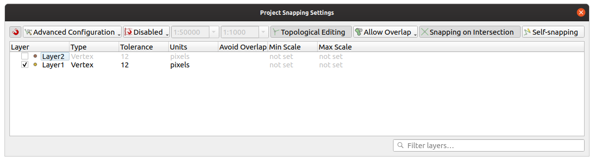
Fig. 12.82 Opções de ajuste (modo de configuração avançada)
Nota
Por padrão, somente os recursos visíveis (os recursos cujo estilo é exibido, exceto as camadas em que a simbologia é “Nenhum símbolo”) podem ser ajustados. Você pode ativar o snap em recursos invisíveis marcando | desmarcado | : guilabel: Habilite o snap em recursos invisíveis na seção: menuselection:` Settings -> Options -> Digitizing`
Dica
** Ativar ajuste por padrão **
Você pode definir o encaixe para ser ativado por padrão em todos os novos projetos na: menuselection: Settings -> Options -> Digitizing Você também pode definir o modo de snap padrão, o valor de tolerância e as unidades, que preencherão a caixa de diálogo: guilabel: opções de snap.
12.3.2.2. Activar atracção nas intersecções
Outra opção disponível é usar | snappingIntersection | : guilabel: encaixe na interseção, que permite encaixar nas interseções geométricas das camadas habilitadas para encaixe, mesmo que não haja vértices nas interseções.
12.3.2.3. Limit snapping to a scale range
In some cases snapping can become very slow. This is often caused by the amount of features in some layers that require a heavy index to compute and maintain. Some parameters exist to enable snapping only when the map view is inside a relevant scale range. This allows to only do the costly index computation related to snapping at a scale where drawing is relevant.
Scale limit to snapping is configured in . Limiting snapping to scale is only available in Advanced Configuration mode.
To limit snapping to a scale range you have three modes available:
Disabled: Snapping is enabled whatever the current map scale is. This is the default mode.
Global: Snapping is limited and only enabled when the current scale of the map is between a global minimum and a global maximum value. When selecting this mode two widgets become available to configure the range of scales in which snapping is enabled.
Per layer: The snapping scale range limit is defined for each layer. When selecting this mode two columns become available to configure the minimum and maximum scales for each layer.
Please note that the minimum and maximum scales follow the QGIS convention: minimum scale is the most “zoomed out” scale while maximum scale is the most “zoomed in”. A minimum or maximum scale that is set to “0” or “not set” is considered not limiting.
12.3.2.4. Self-snapping
The  Self-snapping option allows you to snap to
the geometry that is being edited. Combined with the advanced
digitizing panel, this provides a handy way
to digitize new edges relative to the previous edges or vertices.
Self-snapping can cause invalid geometries, use with caution.
Self-snapping option allows you to snap to
the geometry that is being edited. Combined with the advanced
digitizing panel, this provides a handy way
to digitize new edges relative to the previous edges or vertices.
Self-snapping can cause invalid geometries, use with caution.

Fig. 12.83 Drawing features with self-snapping
12.3.2.5. Snapping on custom grid
A snapping distance can also be customized on a layer basis in the Digitizing tab of the layer properties dialog. With setting the Geometry precision distance, you enable a dotted grid visible when the map canvas is at a coherent scale for display. Snapping can then be performed on the dots of the grid: an added or modified geometry will have all of its vertices snapped automatically to the closest node of the grid. More information at Propriedades de Digitalização.
12.3.3. Edição Topológica
In addition to these snapping options, the Snapping options… dialog () and the Snapping toolbar allow you to enable / disable some other topological functionalities.
12.3.3.1. Ativar edição topológica
A | edição topopológica | : sup: botão Edição topológica ajuda na edição e manutenção de recursos com limites comuns. Com esta opção ativada, o QGIS ‘detecta’ limites compartilhados. Quando você move vértices / segmentos comuns, o QGIS também os move nas geometrias dos recursos vizinhos.
A edição topológica funciona com recursos de diferentes camadas, desde que as camadas estejam visíveis e no modo de edição.
In layer with Z or M values, topological editing will interpolate the Z or M value of the vertex based on the value of the edge used for the connection.
12.3.3.2. Overlapping control
Overlapping prevents you from drawing new features that overlap existing ones in the selected layer, speeding up digitizing of adjacent polygons. It can be controlled by the overlap tool. Three modes are available:
 Allow Overlap (default)
 Avoid Overlap on Active Layer:
prevents any overlap with other features from the layer being edited.
Digitize the new geometries so that they overlap their neighbours and
QGIS will cut the overlapping part(s) of the new geometries and snap them
to the boundary of the existing features. The advantage is that you don’t
have to digitize the common vertices on boundary.
Avoid Overlap on Active Layer:
prevents any overlap with other features from the layer being edited.
Digitize the new geometries so that they overlap their neighbours and
QGIS will cut the overlapping part(s) of the new geometries and snap them
to the boundary of the existing features. The advantage is that you don’t
have to digitize the common vertices on boundary. Follow Advanced Configuration:
allows the overlapping setting to be set on a layer basis in the
Advanced configuration view mode.
Follow Advanced Configuration:
allows the overlapping setting to be set on a layer basis in the
Advanced configuration view mode.
Nota
Se a nova geometria for totalmente coberta pelas existentes, ela será limpa e o QGIS mostrará uma mensagem de erro.
Aviso
** Use com cuidado a opção **: guilabel: Evitar sobreposição ** **
Como essa opção cortará novas geometrias sobrepostas de qualquer camada de polígono, você poderá obter geometrias inesperadas se esquecer de desmarcá-la quando não for mais necessária.
12.3.3.3. Rastreamento automático
Geralmente, ao usar as ferramentas de captura de mapas (adicionar recurso, adicionar peça, adicionar anel, remodelar e dividir), você precisa clicar em cada vértice do recurso. Com o modo de rastreamento automático, você pode acelerar o processo de digitalização, pois não precisa mais colocar manualmente todos os vértices durante a digitalização:
Ative o | rastreio | : sup: Tracing (na barra de ferramentas: guilabel:` Snapping`) pressionando o ícone ou pressionando: kbd: tecla T.
: ref: Ajustar para um vértice ou segmento de um recurso que você deseja rastrear.
Move the mouse over another vertex or segment you’d like to snap and, instead of the usual straight line, the digitizing rubber band represents a path from the last point you snapped to the current position. The tool also works with curved geometries.
O QGIS realmente usa a topologia de recursos subjacente para criar o caminho mais curto entre os dois pontos. O rastreamento exige que o snap seja ativado em camadas rastreáveis para criar o caminho. Você também deve encaixar em um vértice ou segmento existente ao digitalizar e garantir que os dois nós sejam topologicamente conectáveis pelas bordas dos recursos existentes; caso contrário, o QGIS não poderá conectá-los e, portanto, traçará uma única linha reta.
Clique e QGIS posiciona os vértices intermediários seguindo o caminho exibido.
Desdobre o | rastreio | : sup: Ative o rastreio e defina a opção: guilabel:` Offset` para digitalizar um caminho paralelo aos recursos em vez de rastreá-los. Um valor positivo desloca o novo desenho para o lado esquerdo da direção de rastreamento e um valor negativo faz o oposto.
Nota
** Ajuste as configurações de escala ou ajuste do mapa para um rastreamento ideal **
Se houver muitos recursos na exibição do mapa, o rastreamento será desativado para evitar a preparação potencialmente longa da estrutura de rastreamento e a sobrecarga de memória. Após ampliar ou desativar algumas camadas, o rastreamento é ativado novamente.
Nota
** Não adiciona pontos topológicos **
Esta ferramenta não adiciona pontos às geometrias poligonais existentes, mesmo que: guilabel: Edição topológica esteja ativada. Se a precisão da geometria estiver ativada na camada editada, a geometria resultante poderá não seguir exatamente uma geometria existente.
Dica
** Ative ou desative rapidamente o rastreio automático pressionando a tecla **: kbd: T **
Pressionando a tecla: kbd: T, o rastreamento pode ser ativado / desativado a qualquer momento (mesmo durante a digitalização de um recurso), para que seja possível digitalizar partes do recurso com o rastreamento ativado e outras partes com o rastreamento desativado. As ferramentas se comportam como de costume quando o rastreamento está desativado.
Dica
Converter traçado em geometrias curvas
By using you can create curved geometries while digitizing. See digitizing options.
12.3.4. Digitalizar uma camada existente
Por padrão, o QGIS carrega camadas somente leitura. Essa é uma salvaguarda para evitar a edição acidental de uma camada, se houver um deslizamento do mouse. No entanto, você pode optar por editar qualquer camada, desde que o provedor de dados a suporte (consulte: ref: supported_format), e a fonte de dados subjacente é gravável (ou seja, seus arquivos não são somente leitura).
Dica
** Restrinja a permissão de edição em camadas dentro de um projeto **
Na tabela: menuselection: Projeto -> Propriedades … -> Fontes de dados -> Recursos de camadas, você pode optar por definir qualquer camada somente leitura, independentemente da permissão do provedor. Essa pode ser uma maneira prática, em um ambiente de vários usuários, para evitar que usuários não autorizados editem camadas por engano (por exemplo, Shapefile), portanto, dados potencialmente corrompidos. Observe que essa configuração se aplica apenas ao projeto atual.
Em geral, as ferramentas para editar camadas vetoriais são divididas em uma barra de ferramentas de digitalização e uma avançada, descritas na seção: ref: sec_advanced_edit. Você pode selecionar e desmarcar os dois em: menuelection: View -> Barras de ferramentas ->.
Usando as ferramentas básicas de digitalização, você pode executar as seguintes funções:
Ferramenta |
Finalidade |
Ferramenta |
Finalidade |
|---|---|---|---|
|
Acesso para salvar, reverter ou cancelar mudanças em todas as camadas ou em camadas selecionadas simultaneamente |
|
Turn on or off edit status of selected layer(s) based on the active layer status |
|
Salvar edições na camada ativa |
||
|
Digitize using straight segments |
|
Digitize using curve lines |
|
Enable freehand digitizing |
|
Digitize polygon of regular shape |
|
Adicionar novo registro |
|
Adicionar Feição: Ponto de Captura |
|
Adicionar recurso: Linha de captura |
|
Adicionar recurso: Capturar polígono |
|
Ferramenta de Vértice (todas as camadas) |
|
Ferramenta Vértice (camada atual) |
|
Set whether the vertex editor panel should auto-open |
|
Modifique os atributos de todos os recursos selecionados simultaneamente |
|
Excluir feições selecionadas da camada ativa |
|
Recortar feições da camada ativa |
|
Copiar as feições selecionadas da camada ativa |
|
Colar feições na camada ativa |
|
Undo changes in the active layer |
|
Redo changes in active layer |


Observe que, ao usar qualquer uma das ferramentas de digitalização, você ainda pode: ref: ampliar ou deslocar na tela do mapa sem perder o foco na ferramenta.
All editing sessions start by choosing the  Toggle editing option found in the context menu of a given layer,
from the attribute table dialog, the digitizing toolbar or the
menu.
Toggle editing option found in the context menu of a given layer,
from the attribute table dialog, the digitizing toolbar or the
menu.
Quando a camada estiver no modo de edição, botões de ferramentas adicionais na barra de ferramentas de edição ficarão disponíveis e os marcadores aparecerão nos vértices de todos os recursos, a menos que: guilabel: Mostrar marcadores apenas para os recursos selecionados opção em: menuelection:` Settings -> Opções … -> O menu Digitalizar` está marcado.
Dica
Salvar Regularmente
Remember to  Save Layer Edits regularly.
This will also check that your data source can accept all the changes.
Save Layer Edits regularly.
This will also check that your data source can accept all the changes.
12.3.4.1. Geometry editing techniques
When a geometry drawing tool (mainly the ones that add, split, reshape features) is enabled for a line or polygon based layer, you can select the technique for adding new vertices:
The
 Digitize with Segment: draws straight segment
whose start and end points are defined by left clicks.
Digitize with Segment: draws straight segment
whose start and end points are defined by left clicks.The
 Digitize with Curve: draws curve line based on
three consecutive nodes defined by left clicks (start, point along the arc, end).
If the geometry type does not support curves, then consecutive smaller segments
are used to approximate the curvature.
Digitize with Curve: draws curve line based on
three consecutive nodes defined by left clicks (start, point along the arc, end).
If the geometry type does not support curves, then consecutive smaller segments
are used to approximate the curvature.The
 Stream Digitizing: draws lines in freehand mode,
i.e. nodes are added following cursor movement in the map canvas and
a Streaming Tolerance.
The streaming tolerance defines the spacing between consecutive vertices.
Currently, the only supported unit is pixels (
Stream Digitizing: draws lines in freehand mode,
i.e. nodes are added following cursor movement in the map canvas and
a Streaming Tolerance.
The streaming tolerance defines the spacing between consecutive vertices.
Currently, the only supported unit is pixels (px). Only the starting left click and the ending right click are necessary in this mode.The
 Digitize Shape: triggers tools on the
Shape Digitizing Toolbar to draw a polygon of a regular shape.
Digitize Shape: triggers tools on the
Shape Digitizing Toolbar to draw a polygon of a regular shape.
The selected technique remains while switching among the digitizing tools. You can combine any of the first three methods while drawing the same geometry.
12.3.4.2. Adicionando Elementos
Dependendo do tipo de camada, você pode usar o | newTableRow | : sup: Adicionar registro, | capturePoint | : sup: Adicionar recurso de ponto, | captureLine | : sup: Adicionar recurso de linha ou | capturePolygon | : sup: ícones Adicionar recurso de polígono na barra de ferramentas para adicionar novos recursos à camada atual.
To add a geometryless feature, click on the  Add Record
button and you can enter attributes in the feature form that opens.
Add Record
button and you can enter attributes in the feature form that opens.
To create features with the spatially enabled tools, you first digitize the geometry then enter its attributes. To digitize the geometry:
(Optional as it is the default) Select the
Digitize With Segment geometry drawing methodLeft-click on the map area to create the first point of your new feature. For point features, this should be enough and trigger, if required, the feature form to fill in their attributes.
For line or polygon geometries, keep on left-clicking for each additional point you wish to capture. You can rely on the snapping to features options, the snap-to-grid or the advanced digitizing panel to accurately position each vertex.
Along with drawing straight segments between nodes you click one by one, lines and polygons can be:
traced automatically, accelerating the digitization. This will create consecutive straight lines between the vertices you place, following existing features.
free-hand digitized, pressing R or activating
Stream Digitizing.drawn as curve, pressing Ctrl+Shift+G or activating
Digitize with Curve.
Nota
While digitizing line or polygon geometries, you can switch back and forth between the geometry drawing methods, allowing you to create features mixing straight segments, free-hand ones and curved parts.
Press Delete or Backspace key to revert the last node(s) you may wrongly add.
Quando você terminar de adicionar pontos, clique com o botão direito do mouse em qualquer lugar na área do mapa para confirmar que você terminou de inserir a geometria desse recurso.
Dica
** Personalize a faixa de borracha digitalizada **
Ao capturar o polígono, o elástico vermelho por padrão pode ocultar recursos ou locais subjacentes que você deseja capturar um ponto. Isso pode ser corrigido configurando uma opacidade mais baixa (ou canal alfa) no menu: guilabel: Cor de preenchimento do elástico em: seleção de menu: Configurações -> Opções -> Digitalização. Você também pode evitar o uso do elástico marcando: guilabel: Não atualize o elástico durante a edição do nó.
For line feature pressing Shift + right-click will close the line automatically.
The attribute window will appear, allowing you to enter the information for the new feature. Fig. 12.84 shows setting attributes for a fictitious new river. However, in the Digitizing menu under the menu, you can also:
 Suppress attributes pop-up windows after
each created feature to avoid the form opening;
Suppress attributes pop-up windows after
each created feature to avoid the form opening;ou | caixa de seleção | : guilabel: Reutilizar os últimos valores de atributo inseridos para ter campos automaticamente preenchidos na abertura do formulário e apenas digitar valores alterados.
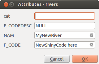
Fig. 12.84 Caixa de diálogo Inserir valores de atributo após digitalizar um novo recurso de vetor
12.3.4.3. Ferramenta Vertex
O QGIS fornece duas ferramentas para interagir com os vértices das feições vetoriais:
 Vertex Tool (Current Layer): only
overlaid features in the active layer (in the Layers
panel) are affected
Vertex Tool (Current Layer): only
overlaid features in the active layer (in the Layers
panel) are affected Vertex Tool (All Layers): any overlaid features
in all editable layers are affected. This allows you to edit features
without switching the active layer or edit multiple layers at once
(e.g., country and their regions boundaries)
Vertex Tool (All Layers): any overlaid features
in all editable layers are affected. This allows you to edit features
without switching the active layer or edit multiple layers at once
(e.g., country and their regions boundaries)
For any editable vector layer, the vertex tools provide manipulation capabilities of feature vertices similar to CAD programs. It is possible to select multiple vertices at once and to move, add or delete them altogether. The vertex tools also support the topological editing feature. They are selection persistent, so when some operation is done, selection stays active for this feature and tool.
Dica
Drawing a series of new vertices
The vertex tool does not support automatic tracing and is optimized for
editing individual vertices and moving or deleting an arbitrary selection
of multiple vertices. Try using the  Reshape Features
tool when you need to replace or insert a series of new vertices,
especially if you want to trace other features.
Reshape Features
tool when you need to replace or insert a series of new vertices,
especially if you want to trace other features.
It is important to set the property  Search Radius:
 to a number greater than zero. Otherwise, QGIS will
not be able to tell which vertex is being edited and will display a warning.
to a number greater than zero. Otherwise, QGIS will
not be able to tell which vertex is being edited and will display a warning.
Dica
Marcadores de Vértice
QGIS supports different kinds of vertex markers:
‘Semi-transparent circle’, ‘Cross’ and ‘None’. To change the marker style,
choose from the
menu, click on the Digitizing
tab and select the appropriate entry.
Operações Básicas
Dada uma camada no modo de edição, comece ativando a ferramenta vértice. Círculos vermelhos aparecerão ao passar o mouse sobre os vértices.
Selecionando os vértices: Você pode selecionar os vértices por:
Clicking on them one at a time holding Shift key pressed
Click-and-dragging a rectangle surrounding the target vertices
Drawing a polygon surrounding the target vertices: Hold Alt and click using the vertex tool to start digitizing a polygon. Each subsequent click adds a new vertex to the rubberband polygon. Backspace or Delete removes last added rubberband vertex. Esc cancels the polygon selection mode, as also does backspacing/deleting all of the rubberband’s vertices. Right click finalizes the polygon digitizing and selects all vertices within the rubberband polygon.
When a vertex is selected, its color changes to blue. To add more vertices to the current selection, hold down the Shift key while proceeding as above. To remove vertices from the selection, hold down Ctrl.
Dica
Feature selection bounds vertex tool
Vertices can be selected across different features (or layers). If you are looking for vertices of a specific feature in a crowded place, first select that feature. Then draw the rectangle or polygon selector with the vertex tool around the vertices: only the selected feature’s vertices are selected.
This is also the case if you display the feature in the vertex editor panel.
Batch vertex selection mode: The batch selection mode can be activated by pressing Shift+R. Select a first node with one single click, and then hover without clicking another vertex. This will dynamically select all the nodes in between using the shortest path (for polygons).
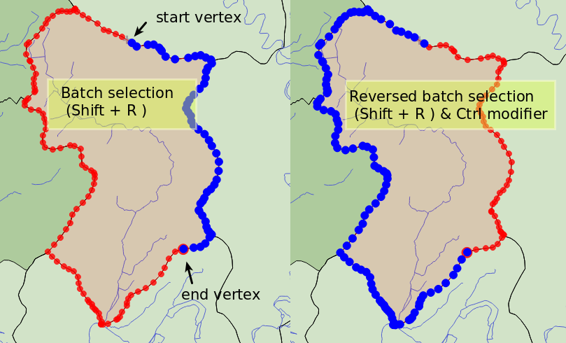
Fig. 12.85 Batch vertex selection using Shift+R
Press Ctrl will invert the selection, selecting the longest path along the feature boundary. Ending your node selection with a second click, or pressing Esc will escape the batch mode.
Adding vertices: To add a vertex to a line or polygon geometry, hold Shift and double-click the place on the segment.
When hovering a segment, a virtual new node appears on the center. Click on it, move the cursor to a new location and click again to add a new vertex. For lines, a virtual node is also proposed at both extremities: click on it, do subsequent clicks and finish with a right-click; this allows to easily extend an existing line.
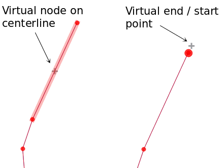
Fig. 12.86 Nós virtuais para adicionar vértices
** Excluindo vértices **: selecione os vértices e clique na tecla: kbd: Excluir. A exclusão de todos os vértices de um recurso gera, se compatível com a fonte de dados, um recurso sem geometria. Observe que isso não exclui o recurso completo, apenas a parte da geometria. Para excluir um recurso completo, use o | deleteSelectedFeatures | : sup: ferramenta Excluir selecionados.
Moving vertices: Select all the vertices you want to move, click on a selected vertex or edge, and click on the desired new location. You can use the snapping to feature capabilities and the Advanced Digitizing Panel constraints for distance, angles, exact X and Y location before the second click. All the selected vertices will be translated.
However, if the snap-to-grid option is enabled, selected vertices are snapped to the closest grid intersection to their translated position. Unselected vertices are also moved to their closest grid intersection. There is no simple translation.
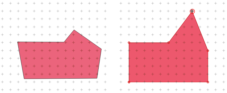
Fig. 12.87 Movendo o vértice superior encaixa todos os vértices na grade
Converting adjacent segments to/from curve: Select the center vertex of the segment you want to convert, hit the O letter key. If the vertex was in a curve, the curve is converted into straight lines. If the vertex was between two straight lines, they are converted into a curve. A first or a last vertex of a line can’t be converted to a center vertex curve. The layer must be compatible with curve geometry type.
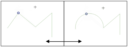
Fig. 12.88 Switch from curve to straight lines with O letter
Each change made with the vertex tool is stored as a separate entry in the Undo dialog. Remember that all operations support topological editing when this is turned on. On-the-fly projection is also supported.
O painel do editor de vértices
With enabling a vertex tool, you also open the Vertex Editor panel. Right-clicking over a feature fills the panel with the list of all the vertices of the feature with their x, y (z, m if applicable) coordinates and r (for the radius, in case of circular geometry). The feature is also made exclusive for editing, meaning that the edit of any other features is disabled:
Selecting a row in the table does select the corresponding vertex in the map canvas, and vice versa.
Clicking or dragging over the map canvas will only select or move vertices and segments of that feature
Change a coordinate in the table and the vertex position is updated. This is a convenient way to edit Z coordinate or M value on vertices.
You can also select multiple rows and delete them altogether.
New vertices can only be added to the bound feature
If you do not want the Vertex Editor panel to immediately show
each time you interact with vertex tools (and potentially hide other panels
or disturb panels placement), uncheck the Auto-open table entry
in the  Options menu at the top of the panel.
You can then also close the panel.
To reopen the panel, you would need to right-click over a panel or toolbar and
select it in the list or tick the Show vertex editor entry in
the Digitizing toolbar.
Options menu at the top of the panel.
You can then also close the panel.
To reopen the panel, you would need to right-click over a panel or toolbar and
select it in the list or tick the Show vertex editor entry in
the Digitizing toolbar.
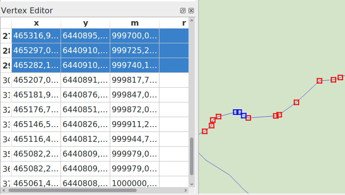
Fig. 12.89 Painel do editor de vértices mostrando os nós selecionados
12.3.4.4. Rules of Z coordinate or M value assignment
Digitizing 3D vector features or features with M value is not that different from (X,Y) 2D layers’. Tools and options described in this chapter are still available and help you place the vertex or point in a planar environment. Then you may need to handle the Z coordinate (or M value) assignment:
By default, QGIS will assign to new vertices the Default Z value (respectively Default M value) set in the tab. If the Advanced Digitizing Panel is in use, then the value is taken from its z (respectively m) widget.
When snapping to a vertex, the new or moved vertex takes the snapped one’s Z or M value.
When snapping to a segment while the topological editing is on, then the new vertex Z or M value is interpolated along the segment.
If the z (respectively m) widget of the Advanced Digitizing Panel is
 locked, then its value is
applied to the vertex, taking precedence over any snapped vertex or segment
Z or M value.
locked, then its value is
applied to the vertex, taking precedence over any snapped vertex or segment
Z or M value.
To edit Z or M values of an existing feature, you can use the Vertex editor panel. To create features with custom Z or M values you may want to rely on the Advanced Digitizing Panel.
12.3.4.5. Cortando, Copiando e Colando Elementos
Os recursos selecionados podem ser recortados, copiados e colados entre as camadas no mesmo projeto QGIS, desde que as camadas de destino estejam definidas como | toggleEditing | : sup: Alterna a edição de antemão.
Dica
** Transforme o polígono em linha e vice-versa usando copiar / colar **
Copie um recurso de linha e cole-o em uma camada de polígono: O QGIS cola na camada de destino um polígono cujo limite corresponde à geometria fechada do recurso de linha. Essa é uma maneira rápida de gerar geometrias diferentes dos mesmos dados.
Features can also be pasted to external applications as text. That is, the features are represented in CSV format, with the geometry data appearing in the OGC Well-Known Text (WKT) format. WKT and GeoJSON features from outside QGIS can also be pasted to a layer within QGIS.
When would the copy and paste function come in handy? Well, it turns
out that you can edit more than one layer at a time
and copy/paste features between layers. Why would we want to do this?
Say we need to do some work on a new layer but only need one or two
lakes, not the 5,000 on our big_lakes layer.
We can create a new layer and use copy/paste to plop the needed lakes
into it.
Como exemplo, vamos copiar alguns lagos para uma nova camada:
Carregue a camada que quer copiar a partir (camada de origem)
Carregue ou crie a camada que quer copiar para (camada de destino)
Começar a editar a camada de destino
Ative a camada de origem clicando nela na legenda
Use the
 Select Features by area or single click
tool to select the feature(s) on the source layer
Select Features by area or single click
tool to select the feature(s) on the source layerClick on the
 Copy Features tool
Ative a camada de destino clicando na legenda
Clique no | editar Colar | : sup: ferramenta Colar recursos
Parar a edição e salvar as alterações
What happens if the source and target layers have different schemas (field names and types are not the same)? QGIS populates what matches and ignores the rest. If you don’t care about the attributes being copied to the target layer, it doesn’t matter how you design the fields and data types. If you want to make sure everything - the feature and its attributes - gets copied, make sure the schemas match.
When you paste features into another layer,
QGIS checks the attribute values against the constraints defined
in the destination layer (for example, NOT NULL, Unique, or expression constraints).
If one or more pasted features contain invalid attribute values that
do not meet these constraints, a dialog will
appear, listing all affected features and fields.
When pasting a single feature, you can decide whether to:
Edit the invalid values directly in the dialog. The corrected values will be used when pasting.
Paste Anyway: the feature is pasted as-is, even with invalid values.

Fig. 12.90 Dialog for handling invalid attribute values when pasting a single feature
When pasting multiple features, the dialog lists all invalid fields across all features, allowing bulk review and correction. You can decide per field or per feature whether to:
Edit the invalid values directly in the dialog. The corrected values will be used when pasting.
Discard All: no features pasted.
Discard All Invalid: pasted only features with valid attribute values.
Paste All (Including Invalid): all features are pasted as-is, even with invalid values.
Skip: skip the specific feature, allowing proceeding with the rest.

Fig. 12.91 Dialog for handling invalid attribute values when pasting multiple features
Nota
Congruência dos Elementos Colados
If your source and destination layers use the same projection, then the pasted features will have geometry identical to the source layer. However, if the destination layer is a different projection, then QGIS cannot guarantee the geometry is identical. This is simply because there are small rounding-off errors involved when converting between projections.
Dica
** Copiar atributo da string para outro **
If you have created a new column in your attribute table with type ‘string’ and want to paste values from another attribute column that has a greater length the length of the column size will be extended to the same amount. This is because the GDAL Shapefile driver knows to auto-extend string and integer fields to dynamically accommodate for the length of the data to be inserted.
12.3.4.6. Apagando os Elementos Selecionados
Se quisermos excluir um recurso inteiro (atributo e geometria), podemos fazer isso selecionando primeiro a geometria usando o regular | select Rectangle | : sup: Selecione Recursos por área ou clique único. A seleção também pode ser feita na tabela de atributos. Depois de definir a seleção, pressione: kbd: Excluir ou: kbd: Backspace ou use a tecla | delete Features Selecionadas | : sup: ferramenta Delete Selected para excluir os recursos. Vários recursos selecionados podem ser excluídos de uma só vez.
The  Cut Features tool on the digitizing toolbar can
also be used to delete features. This effectively deletes the feature but
also places it on a “spatial clipboard”. So, we cut the feature to delete.
We could then use the
Cut Features tool on the digitizing toolbar can
also be used to delete features. This effectively deletes the feature but
also places it on a “spatial clipboard”. So, we cut the feature to delete.
We could then use the  Paste Features tool to put it back,
giving us a one-level undo capability. Cut, copy, and paste work on the
currently selected features, meaning we can operate on more than one at a time.
Paste Features tool to put it back,
giving us a one-level undo capability. Cut, copy, and paste work on the
currently selected features, meaning we can operate on more than one at a time.
12.3.4.7. Retroceder e Retomar
The  Undo and
  Redo tools allows you to undo or redo
vector editing operations. There is also a dockable widget, which shows all
operations in the undo/redo history (see Fig. 12.92). This widget is not
displayed by default; it can be displayed by right-clicking on the toolbar and
activating the Undo/Redo Panel checkbox. The Undo/Redo capability
is however active, even if the widget is not displayed.
Redo tools allows you to undo or redo
vector editing operations. There is also a dockable widget, which shows all
operations in the undo/redo history (see Fig. 12.92). This widget is not
displayed by default; it can be displayed by right-clicking on the toolbar and
activating the Undo/Redo Panel checkbox. The Undo/Redo capability
is however active, even if the widget is not displayed.
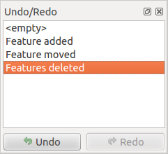
Fig. 12.92 Refazer e desfazer etapas de digitalização
When Undo is hit or Ctrl+Z (or Cmd+Z) pressed, the state of all features and attributes are reverted to the state before the reverted operation happened. Changes other than normal vector editing operations (for example, changes done by a plugin) may or may not be reverted, depending on how the changes were performed.
Para usar a tela histórico de desfazer / refazer, basta clicar para selecionar uma operação na lista de histórico. Todas as feições serão revertidas para o estado em que estavam depois da operação selecionada.
12.3.4.8. Salvando as Camadas Editadas
When a layer is in editing mode, any changes remain in the memory of QGIS.
Therefore, they are not committed/saved immediately to the data source or disk.
If you want to save edits to the current layer but want to continue editing
without leaving the editing mode, you can click the
Save Layer Edits button. When you turn editing mode off with
Toggle editing (or quit QGIS for that matter),
you are also asked if you want to save your changes or discard them.
Se as alterações não puderem ser salvas (por exemplo, disco cheio ou os atributos tiverem valores fora do intervalo), o estado na memória do QGIS será preservado. Isso permite que você ajuste suas edições e tente novamente.
Dica
Integridade dos dados
É sempre uma boa idéia fazer backup da fonte de dados antes de começar a editar. Embora os autores do QGIS tenham se esforçado para preservar a integridade dos seus dados, não oferecemos garantia a esse respeito.
Salvando várias camadas ao mesmo tempo
Esse recurso permite a digitalização de várias camadas. Escolha | arquivo Salvar como | : guilabel: Salvar para camadas selecionadas para salvar todas as alterações feitas em várias camadas. Você também tem a oportunidade de | reverter edições | : guilabel: Reversão para camadas selecionadas, para que a digitalização possa ser retirada para todas as camadas selecionadas. Se você deseja parar de editar as camadas selecionadas, cancele Edições | : guilabel: Cancelar para a (s) camada (s) selecionada (s) é uma maneira fácil.
As mesmas funções estão disponíveis para a edição de todas as camadas do projeto.
Dica
** Use o grupo de transações para editar, salvar ou reverter várias alterações de camada ao mesmo tempo **
When working with layers from the same PostGreSQL database, activate the Automatically create transaction groups where possible option in to sync their behavior (enter or exit the edit mode, save or rollback changes at the same time).
12.3.5. Digitalização Avançada
Ícone |
Finalidade |
Ícone |
Finalidade |
|---|---|---|---|
|
Ativar ferramentas avançadas de digitalização |
||
|
Mover feições |
|
Copiar e Mover Feição(ões) |
|
Rodar Elemento(s) |
|
Simplificar elemento |
|
Scale Feature |
||
|
Adicionar Anel |
|
Adicionar Parte |
|
Preenchimento Anel |
|
Swap direction |
|
Apagar Anel |
|
Apagar Parte |
|
Curva de Afastamento |
|
Refazer elementos |
|
Dividindo partes |
|
Dividir Elementos |
|
Juntar Atributos dos Elementos Selecionados |
|
Juntar Elementos Selecionados |
|
Rodar Símbolos de Pontos |
|
Offset Point Symbols |
|
Trim or Extend Feature |


12.3.5.1. Mover feições
The  Move Feature(s) tool allows you to move existing features:
Selecionar as feições a serem movidas.
Click on the map canvas to indicate the origin point of the displacement; you can rely on snapping capabilities to select an accurate point.
You can also take advantages of the advanced digitizing constraints to accurately set the origin point coordinates. In that case:
Primeiro clique no | cad | para ativar o painel.
Digite `` x`` e insira o valor correspondente ao ponto de origem que você deseja usar. Em seguida, pressione o botão | bloqueado | ao lado da opção para bloquear o valor.
Faça o mesmo para a coordenada
y.Click on the map canvas and your origin point is placed at the indicated coordinates.
Move over the map canvas to indicate the destination point of the displacement, still using snapping mode or, as above, use the advanced digitizing panel which would provide complementary
distanceandangleplacement constraints to place the end point of the translation.Click on the map canvas: the whole features are moved to new location.
Likewise, you can create a translated copy of the feature(s) using the
 Copy and Move Feature(s) tool.
Nota
If no feature is selected when you first click on the map canvas with any of the Move Feature(s) or Copy and Move Feature(s) tools, then only the feature under the mouse is affected by the action. So, if you want to move several features, they should be selected first.
12.3.5.2. Rodar Elemento(s)
Use the  Rotate Feature(s) tool to rotate one or multiple
features in the map canvas:
Rotate Feature(s) tool to rotate one or multiple
features in the map canvas:
Press the
Rotate Feature(s) iconThen click on the feature to rotate. The feature’s centroid is referenced as rotation center, a preview of the rotated feature is displayed and a widget opens showing the current Rotation angle.
Click on the map canvas when you are satisfied with the new placement or manually enter the rotation angle in the text box. You can also use the Snap to ° box to constrain the rotation values.
If you want to rotate several features at once, they shall be selected first, and the rotation is by default around the centroid of their combined geometries.
You can also use an anchor point different from the default feature centroid: press the Ctrl button, click on the map canvas and that point will be used as the new rotation center.
If you hold Shift before clicking on the map, the rotation will be done in 45 degree steps, which can be modified afterwards in the user input widget.
To abort feature rotation, press the ESC button or click on the
Rotate Feature(s) icon.
12.3.5.3. Scale Feature
The  Scale Feature tool is similar to the Rotate feature. Though instead of performing
a rotation of selected features, it rescales their geometry. The change is
performed in relation to the anchor point and the scale ratio can be manually specified
in the widget that appears in the upper corner of the canvas.
Scale Feature tool is similar to the Rotate feature. Though instead of performing
a rotation of selected features, it rescales their geometry. The change is
performed in relation to the anchor point and the scale ratio can be manually specified
in the widget that appears in the upper corner of the canvas.
12.3.5.4. Simplificar elemento
The  Simplify Feature tool allows you to interactively
reshape a line or polygon geometry by reducing or densifying the number of
vertices, as long as the geometry remains valid:
Simplify Feature tool allows you to interactively
reshape a line or polygon geometry by reducing or densifying the number of
vertices, as long as the geometry remains valid:
Select the
Simplify Feature tool.Click on the feature or drag a rectangle over the features.
A dialog pops up allowing you to define the Method to apply, ie whether you would like to:
simplify the geometry, meaning less vertices than the original. Available methods are
Simplify by distance,Simplify by snapping to gridorsimplify by area (Visvalingam). You’d then need to indicate the value of Tolerance inLayer units,Pixelsormap unitsto use for simplification. The higher the tolerance is the more vertices can be deleted.or densify the geometries with new vertices thanks to the
Smoothoption: for each existing vertex, two vertices are placed on each of the segments originated from it, at an Offset distance representing the percentage of the segment length. You can also set the number of Iterations the placement would be processed: the more iterations, the more vertices and smoother is the feature.
Settings that you used will be saved when leaving a project or an edit session. So you can go back to the same parameters the next time you simplify a feature.
A summary of the modifications that would apply is shown at the bottom of the dialog, listing number of features and number of vertices (before and after the operation and the ratio the change represents). Also, in the map canvas, the expected geometry is displayed over the existing one, using the rubberband color.
When the expected geometry fits your needs, click OK to apply the modification. Otherwise, to abort the operation, you can either press Cancel or right-click in the map canvas.
Nota
Unlike the feature simplification option in menu which simplifies the geometry just for rendering,
the Simplify Feature tool permanently modifies
feature’s geometry in data source.
12.3.5.5. Adicionar Parte
You can  Add Part to a selected feature generating a
multipoint, multiline or multipolygon feature. The new part must be digitized
outside the existing one which should be selected beforehand.
Add Part to a selected feature generating a
multipoint, multiline or multipolygon feature. The new part must be digitized
outside the existing one which should be selected beforehand.
The Add Part can also be used to add a geometry to a geometryless
feature. First, select the feature in the attribute table and digitize the new
geometry with the Add Part tool.
Nota
Order of vertices in polygon parts
Unlike the OGC standards, QGIS doesn’t constrain vertices of the exterior boundary of a polygon feature to be ordered counterclockwise. Thus, you can find both directions in a layer. However, every parts of the same multipolygon feature will have their outer vertices ordered following the same direction.
You can however use the Regra de força da mão direita. algorithm to constrain features of a layer to have vertices of their outer boundaries ordered in the clockwise direction.
12.3.5.6. Apagar Parte
The  Delete Part tool allows you to delete parts from
multifeatures (e.g., to delete polygons from a multi-polygon feature). This
tool works with all multi-part geometries: point, line and polygon. Furthermore,
it can be used to totally remove the geometric component of a feature.
To delete a part, simply click within the target part.
Delete Part tool allows you to delete parts from
multifeatures (e.g., to delete polygons from a multi-polygon feature). This
tool works with all multi-part geometries: point, line and polygon. Furthermore,
it can be used to totally remove the geometric component of a feature.
To delete a part, simply click within the target part.
12.3.5.7. Adicionar Anel
You can create ring polygons using the  Add Ring icon in the toolbar.
This means that inside an existing area, it is possible to digitize further polygons
that will occur as a ‘hole’, so only the area between the boundaries
of the outer and inner polygons remains as a ring polygon.
Add Ring icon in the toolbar.
This means that inside an existing area, it is possible to digitize further polygons
that will occur as a ‘hole’, so only the area between the boundaries
of the outer and inner polygons remains as a ring polygon.
To add a ring:
Select the feature(s) to modify
Activate the
Add Ring toolDraw a polygon within the selected geometries, using the aforementioned techniques. A hole appears in the selected geometries.
If no geometry is selected when the ring is drawn, then a hole is added to each of the polygons the ring is drawn over.
Nota
Order of vertices in polygon rings
Unlike the OGC standards, QGIS doesn’t constrain vertices of the exterior boundary of a polygon feature to be ordered counterclockwise. Thus, you can find both directions in a layer. However, every rings of the same (multi)polygon feature will have their vertices ordered in the opposite direction to the outer boundary’s.
You can however use the Regra de força da mão direita. algorithm to constrain features of a layer to have vertices of their outer boundaries ordered in the clockwise direction, and vertices of their interior rings ordered in the counter-clockwise direction.
12.3.5.8. Preenchimento Anel
The  Fill Ring tool helps you create polygon feature that
totally falls within another one without any overlapping area; that is the new
feature covers a hole within the existing one. To create such a feature:
Fill Ring tool helps you create polygon feature that
totally falls within another one without any overlapping area; that is the new
feature covers a hole within the existing one. To create such a feature:
Select the
Fill Ring tool.Desenhe um novo polígono sobre o recurso existente: o QGIS adiciona um anel à sua geometria (como se você usasse a ferramenta | addRing |: sup: Add Ring) e cria um novo recurso cuja geometria corresponde ao anel (como se você: ref : traçado sobre os limites internos com a ferramenta | capturePolygon |: sup: Adicionar recurso de polígono).
Or alternatively, if the ring already exists on the feature, place the mouse over the ring and left-click while pressing Shift: a new feature filling the hole is drawn at that place.
The Feature Attributes form of the new feature opens, pre-filled with values of the “parent” feature and/or fields constraints.
12.3.5.9. Apagar Anel
The  Delete Ring tool allows you to delete rings within
an existing polygon, by clicking inside the hole. This tool only works with
polygon and multi-polygon features. It doesn’t
change anything when it is used on the outer ring of the polygon.
Delete Ring tool allows you to delete rings within
an existing polygon, by clicking inside the hole. This tool only works with
polygon and multi-polygon features. It doesn’t
change anything when it is used on the outer ring of the polygon.
12.3.5.10. Refazer elementos
You can reshape line and polygon features using the
Reshape Features tool on the toolbar. For lines, it replaces the line
part from the first to the last intersection with the original line.
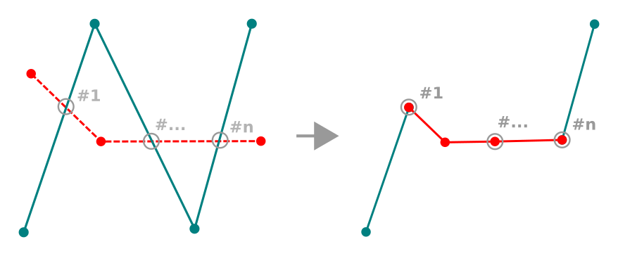
Fig. 12.93 Remodelar linha
Dica
Extend linestring geometries with reshape tool
Use the Reshape Features tool to extend existing linestring
geometries: snap to the first or last vertex of the line and draw a new one.
Validate and the feature’s geometry becomes the combination of the two lines.
For polygons, it will reshape the polygon’s boundary. For it to work, the reshape tool’s line must cross the polygon’s boundary at least twice. To draw the line, click on the map canvas to add vertices. To finish it, just right-click. Like with the lines, only the segment between the first and the last intersections is considered. The reshape line’s segments that are inside the polygon will result in cropping it, where the ones outside the polygon will extend it.
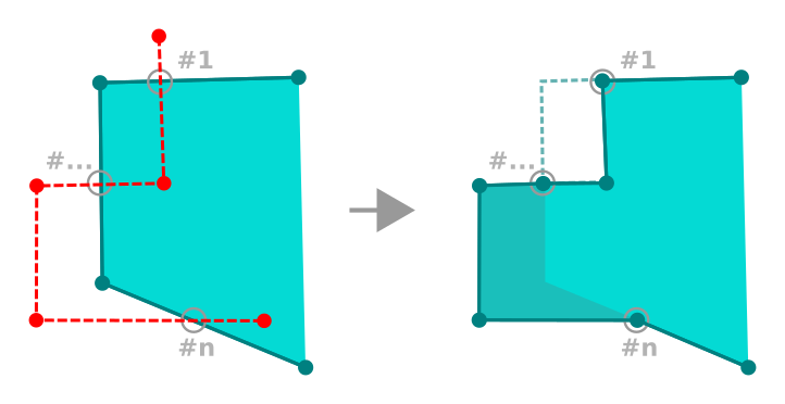
Fig. 12.94 Remodelar polígono
With polygons, reshaping can sometimes lead to unintended results. It is mainly useful to replace smaller parts of a polygon, not for major overhauls, and the reshape line is not allowed to cross several polygon rings, as this would generate an invalid polygon.
Nota
A ferramenta de mudança de forma pode alterar a posição inicial de um anel ou de uma linha poligonal fechada. Assim, o ponto que está representada ‘duas vezes’ não será o mesmo mais. Isto pode não ser um problema para a maioria das aplicações, mas é algo a considerar.
12.3.5.11. Curvas de Afastamento
The  Offset Curve tool creates parallel shifts of
line layers.
The tool can be applied to the edited layer (the geometries are modified)
or also to background layers (in which case it creates copies of the lines /
rings and adds them to the edited layer).
It is thus ideally suited for the creation of distance line layers.
The User Input dialog pops-up, showing the displacement distance
and other settings.
Offset Curve tool creates parallel shifts of
line layers.
The tool can be applied to the edited layer (the geometries are modified)
or also to background layers (in which case it creates copies of the lines /
rings and adds them to the edited layer).
It is thus ideally suited for the creation of distance line layers.
The User Input dialog pops-up, showing the displacement distance
and other settings.
To create a shift of a line or polygon layer, you must first go into editing mode
and activate the Offset Curve tool.
Then click on a feature to shift it.
Move the mouse and click where wanted or enter the desired distance in
the user input widget. Holding Ctrl during the 2nd click will make an offset copy.
Your changes may then be saved with the
Save Layer Edits tool.
For geometries on background layers make sure that snapping is on and hold Ctrl to select the geometry from the background. Also hold Ctrl when doing the second click. Geometries will be converted to the target layer geometry type.
QGIS options dialog (Digitizing tab then Curve offset tools section) or
the  icon in the User Input dialog allows
you to configure some parameters like Join style,
Quadrant segments, Miter limit and End cap style.
icon in the User Input dialog allows
you to configure some parameters like Join style,
Quadrant segments, Miter limit and End cap style.
12.3.5.12. Linha Invertida
Changing the direction of a line geometry can be useful for cartographical purposes (e.g., for orienting symbols or labels that follow the line direction) or when preparing for network analysis where the direction of flow or travel matters.
This tool works only on line layers. For multipart lines, you can reverse individual parts without affecting the other parts of the feature.
Para alterar a direção de uma linha:
Select a line layer in the Layers panel and make it editable.
Activate the reverse line tool by clicking
 Reverse line in the Advanced Digitizing toolbar.
Move the pointer over a line feature. The part under the cursor is highlighted.
Click on the line: the direction of the line (or part) is reversed.
You can reverse other lines by clicking on them.
Dica
For bulk line direction changes, use the Direção reversa da linha processing algorithm which can reverse all lines in a layer or a selection at once.
12.3.5.13. Dividir Elementos
Use the  Split Features tool to split a feature into two
or more new and independent features, ie. each geometry corresponding to a new
row in the attribute table.
Split Features tool to split a feature into two
or more new and independent features, ie. each geometry corresponding to a new
row in the attribute table.
Para quebrar feições de linha ou polígono:
Select the
Split Features tool.Draw a line across the feature(s) you want to split. If a selection is active, only selected features are split. The original feature is then assigned the biggest geometry resulting from the splitting, and new features are created for the remaining parts. Fields of the features are filled/updated according to the datasource provider rules or their splitting policy.
You can then as usual modify any of the attributes of any resulting feature.
Dica
Split a polyline into new features in one-click
Using the Split Features tool, snap and click on an
existing vertex of a polyline feature to split that feature into two new features.
12.3.5.14. Dividindo partes
No QGIS, é possível dividir as partes de um recurso de várias partes para aumentar o número de partes. Basta desenhar uma linha na parte que você deseja dividir usando o | peças separadas | : sup: ícone Split Parts.
Dica
** Divida uma polilinha em novas peças com um clique **
Using the  Split Parts tool, snap and click on an
existing vertex of a polyline feature to split the feature into two new
polylines belonging to the same feature.
Split Parts tool, snap and click on an
existing vertex of a polyline feature to split the feature into two new
polylines belonging to the same feature.
12.3.5.15. Juntar elementos selecionados
The  Merge Selected Features tool allows you to create
a new feature by merging existing ones: their geometries are merged to generate
a new one. If features don’t have common boundaries,
a multipolygon/multipolyline/multipoint feature is created.
Merge Selected Features tool allows you to create
a new feature by merging existing ones: their geometries are merged to generate
a new one. If features don’t have common boundaries,
a multipolygon/multipolyline/multipoint feature is created.
Primeiro, selecione os recursos que você deseja combinar.
Em seguida, pressione o | mergeFeatures | : sup: botão “Mesclar recursos selecionados”.
In the new dialog, the Merge line at the bottom of the table shows the attributes of the resulting feature. If any Merge policy have been defined, they are automatically applied to populate this row. However, you can override these values manually. Modify the values in the following ways:
substituindo manualmente o valor na célula correspondente;
selecting a row in the table and pressing Take attributes from selected feature to use the values of this initial feature;
pressing the Take attributes from the largest geometry to use the attributes from the longest line feature, the largest polygon, or the multipoints with the most parts;
pressing Skip all fields to use empty attributes;
expanding the drop down menu at the top of the table, select any of the above options to apply to the corresponding field only. There, you can also choose to aggregate the initial features attributes (Minimum, Maximum, Median, Sum, Count, Concatenation… depending on the type of the field. see Statistical Summary Panel for the full list of functions).
Nota
If the layer has default values or clauses present on fields, these are used as the initial value for the merged feature.
Press OK to apply the modifications. A single (multi)feature is created in the layer, replacing the previously selected ones.
12.3.5.16. Juntar os atributos dos elementos selecionados
The  Merge Attributes of Selected Features tool
allows you to apply same attributes to features without merging their boundaries.
The dialog is the same as the
Merge Attributes of Selected Features tool
allows you to apply same attributes to features without merging their boundaries.
The dialog is the same as the Merge Selected Features tool’s except that
unlike that tool, selected objects are kept with their geometry while some of their
attributes are made identical.
12.3.5.17. Rodar Símbolos de Pontos
The  Rotate Point Symbols allows you to individually
change the rotation of point symbols in the map canvas.
Rotate Point Symbols allows you to individually
change the rotation of point symbols in the map canvas.
First, you need to indicate the field to store the rotation value in. This is made by assigning a field to the symbol data-defined rotation property:
In the dialog, browse to the symbol editor dialog.
Click the
 Data-defined override widget near the
Rotation option of the top Marker level (preferably)
of the symbol layers.
Data-defined override widget near the
Rotation option of the top Marker level (preferably)
of the symbol layers.Choose a field in the Field Type combobox. Values of this field are hence used to rotate each feature’s symbol accordingly.
You can also check the Store data in project entry to generate an auxiliary data storage field to control the rotation value.
Nota
Certifique-se de que o mesmo campo seja atribuído a todas as camadas de símbolos
A configuração do campo de rotação definido por dados no nível mais alto da árvore de símbolos o propagará automaticamente para todas as camadas de símbolos, um pré-requisito para executar a rotação gráfica de símbolos com a ferramenta: guilabel: Rotate Point Symbols. De fato, se uma camada de símbolo não tiver o mesmo campo anexado à sua propriedade de rotação, a ferramenta não funcionará.
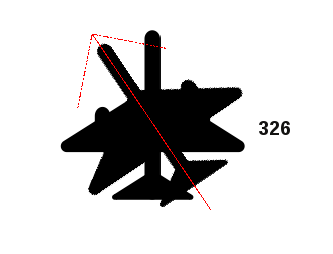
Fig. 12.95 Girando um símbolo de ponto
Then click on a point symbol in the map canvas with the
Rotate Point Symbols toolMove the mouse around. A red arrow with the rotation value will be visualized (see Fig. 12.95). If you hold the Ctrl key while moving, the rotation will be done in 15 degree steps.
Quando você obtiver o valor do ângulo esperado, clique novamente. O símbolo é renderizado com esta nova rotação e o campo associado é atualizado de acordo.
Você pode clicar com o botão direito do mouse para abortar a rotação do símbolo.
12.3.5.18. Offset Point Symbols
The  Offset Point Symbols allows you to interactively
change the rendered position of point symbols in the map canvas. This tool behaves
like the Rotate Point Symbols tool except that it
requires you to connect a field to the data-defined Offset (X,Y)
property of each layer of the symbol. The field will then be populated with the
offset coordinates for the features whose symbol is moved in the map canvas.
Offset Point Symbols allows you to interactively
change the rendered position of point symbols in the map canvas. This tool behaves
like the Rotate Point Symbols tool except that it
requires you to connect a field to the data-defined Offset (X,Y)
property of each layer of the symbol. The field will then be populated with the
offset coordinates for the features whose symbol is moved in the map canvas.
Associate a field to the data-defined widget of the Offset (X,Y) property of the symbol. If the symbol is made with many layers, you may want to assign the field to each of them
Select the
Offset Point Symbols toolClique em um símbolo de ponto
Mover para um novo local
Clique novamente. O símbolo é movido para o novo local. Os valores de deslocamento da posição original são armazenados no campo vinculado.
You can right-click to abort symbol offset.
Nota
The Offset Point Symbols tool doesn’t
move the point feature itself; you should use the
Vertex Tool (Current Layer) or  Move Feature
tool for this purpose.
Move Feature
tool for this purpose.
12.3.5.19. Recortar / estender o recurso
The  Trim/Extend tool allows you to shorten or lengthen
segments of a (multi)line or (multi)polygon geometry to converge with a
selected segment (the cutting line). This results in a modified geometry
with a vertex snapped to a reference segment or in its prolongation.
Depending on how the selected geometries are placed in relation to each
other, the tool will either:
Trim/Extend tool allows you to shorten or lengthen
segments of a (multi)line or (multi)polygon geometry to converge with a
selected segment (the cutting line). This results in a modified geometry
with a vertex snapped to a reference segment or in its prolongation.
Depending on how the selected geometries are placed in relation to each
other, the tool will either:
Aparar: remove partes do segmento de linha ou limite de polígono, além da linha de corte
Estender: estende os limites dos polígonos ou segmentos de linha para que eles possam se encaixar na linha de corte.
A fim de aparar ou ampliar as geometrias existentes:
Select the
Trim/Extend toolClick the reference segment, i.e., the segment with respect to which you want to extend or trim another segment. It doesn’t need to be on the active layer. A red dotted line appears, visually extending the reference segment across the map canvas according to the active layer’s CRS.
Hover over the target segment, i.e., the one you want to trim or extend. It does not need to be the last segment of the geometry, but has to be on the active layer. QGIS displays a preview of the feature’s geometry with the segment limited to its intersection with the highlighted red dotted extending line.
If an extension of the segment is required, click anywhere on the segment.
In the case of a trim, click the part that should remain.
In either case, the feature’s geometry is updated accordingly. When both segments are in 3D, the tool performs an interpolation on the limit segment to get the Z value.
If you need to use the same reference segment for trimming or extending many features:
Press Shift while selecting the reference segment.
Click consecutively on the segments to modify and each will be trimmed or extended accordingly.

Fig. 12.96 Trimming and extending multiple lines from different layers in different CRS
Nota
Snapping is automatically enabled when this tool is activated. Your original snapping settings will be restored once the tool is deactivated.
Atenção
Pay attention to the modified geometry while using the
Trim/Extend tool. Depending on the inputs, it can create invalid
geometries, potentially resulting in failure at layer saving.
12.3.6. Digitalização de forma
The Shape Digitizing toolbar offers a set of tools to draw lines
or polygons features of regular shape.
It is synchronized with the Digitize Shape
geometry drawing method you can select on the Digitizing Toolbar.
To use it:
Display the toolbar:
Select a tool that creates or modifies the shape of a geometry, e.g.
 Add line feature,
  Add polygon feature,
Add part, Add ring, Reshape Features, …
Add polygon feature,
Add part, Add ring, Reshape Features, …The
Digitize with segment button
on the Digitizing Toolbar is enabled.
The first time, you may need to switch it to the Digitize Shape
in order to enable tools on the Shape Digitizing toolbar.Pick a shape digitizing tool and draw.
12.3.6.1. Circular string by radius
The  Circular string by radius button allows
to add line or polygon features with a circular geometry, given two nodes
on the curve and a radius:
Circular string by radius button allows
to add line or polygon features with a circular geometry, given two nodes
on the curve and a radius:
Left click twice to place the two points on the geometry.
A Radius widget in the top right corner of the map canvas displays current radius (corresponding to distance between the points). Edit that field to the value you want.
An overview of the arcs matching these constraints is displayed while moving around the cursor. Right-click to validate when the expected arc is shown.
Add a new point to start shaping another arc.
Nota
Curved geometries are stored as such only in compatible data provider
Although QGIS allows to digitize curved geometries within any editable data format, you need to be using a data provider (e.g. PostgreSQL, Oracle Spatial, memory layer, GML or WFS) that supports curves to have features stored as curved, otherwise QGIS segmentizes the circular arcs.
12.3.6.2. Desenhar círculos
Há um conjunto de ferramentas para desenhar círculos. As ferramentas são descritas abaixo.
Circles are converted into circular strings. Therefore, as explained in Circular string by radius, if allowed by the data provider, it will be saved as a curved geometry, if not, QGIS will segmentize the circular arcs.
 Circle from 2 points: The two points define the diameter
and the orientation of the circle. (Left-click, right-click)
Circle from 2 points: The two points define the diameter
and the orientation of the circle. (Left-click, right-click) Circle from 3 points: Draws a circle from three
known points on the circle. (Left-click, left-click, right-click)
Circle from 3 points: Draws a circle from three
known points on the circle. (Left-click, left-click, right-click) Circle by a center point and another point: Draws a circle
with a given center and a point on the circle (Left-click, right-click).
When used with the O painel Digitalização avançada this tool can become a
“Add circle from center and radius” tool by setting and locking the distance
value after first click.
Circle by a center point and another point: Draws a circle
with a given center and a point on the circle (Left-click, right-click).
When used with the O painel Digitalização avançada this tool can become a
“Add circle from center and radius” tool by setting and locking the distance
value after first click. Circle from 3 tangents: Draws a circle that is
tangential to three segments. Note that you must activate snapping to
segments (See Setting the snapping tolerance and search radius). Click on a segment to add a
tangent. If two tangents are parallel, the coordinates of the click on the
first parallel tangent are used to determine the positioning of the circle.
If three tangents are parallel, an error message appears and the input
is cleared. (Left-click, left-click, right-click)
Circle from 3 tangents: Draws a circle that is
tangential to three segments. Note that you must activate snapping to
segments (See Setting the snapping tolerance and search radius). Click on a segment to add a
tangent. If two tangents are parallel, the coordinates of the click on the
first parallel tangent are used to determine the positioning of the circle.
If three tangents are parallel, an error message appears and the input
is cleared. (Left-click, left-click, right-click) Circle from 2 tangents and a point: Similar
to circle from 3 tangents, except that you have to select two tangents, enter
a radius and select the desired center.
Circle from 2 tangents and a point: Similar
to circle from 3 tangents, except that you have to select two tangents, enter
a radius and select the desired center.
12.3.6.3. Desenhar Elipses
There is a set of tools for drawing ellipses. The tools are described below.
Ellipses cannot be converted as circular strings, so they will always be segmented.
 Ellipse from center and two points: Draws an
ellipse with a given center, major axis and minor axis. (Left-click,
left-click, right-click)
Ellipse from center and two points: Draws an
ellipse with a given center, major axis and minor axis. (Left-click,
left-click, right-click) Ellipse from center and a point: Draws an
ellipse into a bounding box with the center and a corner. (Left-click,
right-click)
Ellipse from center and a point: Draws an
ellipse into a bounding box with the center and a corner. (Left-click,
right-click) Ellipse from extent: Draws an ellipse into a bounding
box with two opposite corners. (Left-click, right-click)
Ellipse from extent: Draws an ellipse into a bounding
box with two opposite corners. (Left-click, right-click) Ellipse from foci: Draws an ellipse by 2 points for
foci and a point on the ellipse. (Left-click, left-click, right-click)
Ellipse from foci: Draws an ellipse by 2 points for
foci and a point on the ellipse. (Left-click, left-click, right-click)
12.3.6.4. Desenhar Retângulos
There is a set of tools for drawing rectangles. The tools are described below.
 Rectangle from center and a point: Draws a
rectangle from the center and a corner. (Left-click, right-click)
Rectangle from center and a point: Draws a
rectangle from the center and a corner. (Left-click, right-click) Rectangle from extent: Draws a rectangle from two
opposite corners. (Left-click, right-click)
Rectangle from extent: Draws a rectangle from two
opposite corners. (Left-click, right-click) Rectangle from 3 points (distance): Draws an
oriented rectangle from three points. The first and second points determine the
length and angle of the first edge. The third point determines the length of the
other edge. One can use O painel Digitalização avançada to set the length of the
edges. (Left-click, left-click, right-click)
Rectangle from 3 points (distance): Draws an
oriented rectangle from three points. The first and second points determine the
length and angle of the first edge. The third point determines the length of the
other edge. One can use O painel Digitalização avançada to set the length of the
edges. (Left-click, left-click, right-click) Rectangle from 3 points (projected): Same as
the preceding tool, but the length of the second edge is computed from the
projection of the third point on the first edge. (Left-click, left-click,
right-click)
Rectangle from 3 points (projected): Same as
the preceding tool, but the length of the second edge is computed from the
projection of the third point on the first edge. (Left-click, left-click,
right-click)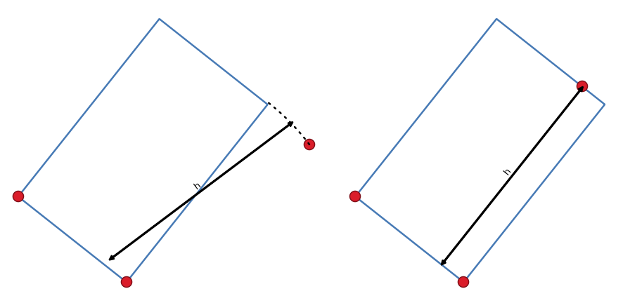
Fig. 12.97 Draw rectangle from 3 points using distance (right) and projected (left)
12.3.6.5. Desenhar Polígonos Regulares
There is a set of tools for drawing regular polygons. The tools are described below. Left-click to place the first point. A dialog appears, where you can set the number of polygon edges. Right-click to finish the regular polygon.
 Regular polygon from two points: Draws a regular
polygon where the two points determine the length and angle of the first edge.
Regular polygon from two points: Draws a regular
polygon where the two points determine the length and angle of the first edge. Regular polygon from center and a point:
Draws a regular polygon from the provided center point. The second point determines the
angle and distance to the middle of an edge.
Regular polygon from center and a point:
Draws a regular polygon from the provided center point. The second point determines the
angle and distance to the middle of an edge. Regular polygon from center and a corner:
Same as the preceding tool, but the second point determines the angle and
distante to a vertex.
Regular polygon from center and a corner:
Same as the preceding tool, but the second point determines the angle and
distante to a vertex.
12.3.7. O painel Digitalização avançada
When capturing, reshaping, splitting new or existing geometries you also have the possibility to use the Advanced Digitizing panel. You can digitize lines exactly parallel or perpendicular to a particular angle or lock lines to specific angles. Furthermore, you can make a precise definition of your new geometry by entering X and Y coordinates as well as Z for 3D features, or M values.
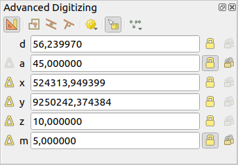
Fig. 12.98 O painel Digitalização avançada
The Advanced Digitizing panel can be opened either with a right-click
on the toolbar, from menu or pressing
Ctrl+4. Once the panel is visible, click the  Enable advanced
digitizing tools button to activate the set of tools.
Enable advanced
digitizing tools button to activate the set of tools.
Nota
As ferramentas não são habilitadas se a visão do mapa está em coordenadas geográficas.
The aim of the Advanced Digitizing tool is to lock coordinates, lengths, and angles when moving the mouse during the digitizing in the map canvas.
You can also create constraints with relative or absolute reference. Relative reference means that the next vertex constraints’ values will be relative to the previous vertex or segment.
12.3.7.1. The toolbar
At the top of the Digitizing panel, you find the following buttons:
- Enable advanced digitizing tools
 Construction mode: allows to capture the clicks’
positions to reuse as reference points to lock distance, angle, X, Y, Z or M
relative values. More details at Modo de construção.
Construction mode: allows to capture the clicks’
positions to reuse as reference points to lock distance, angle, X, Y, Z or M
relative values. More details at Modo de construção. Parallel to draw a line parallel to an existing one
(more at Linhas paralelas e perpendiculares)
Parallel to draw a line parallel to an existing one
(more at Linhas paralelas e perpendiculares) Perpendicular to draw a line perpendicular to an
existing one (more at Linhas paralelas e perpendiculares)
Perpendicular to draw a line perpendicular to an
existing one (more at Linhas paralelas e perpendiculares) Construction Tools provides a couple of options that
constrain the vertices placement based on extrapolated coordinates of
existing elements:
Construction Tools provides a couple of options that
constrain the vertices placement based on extrapolated coordinates of
existing elements: Line Extension: hover over a segment and you get
a purple dotted line extending the segment across the map canvas.
You can snap the vertex anywhere on this virtual line.
Line Extension: hover over a segment and you get
a purple dotted line extending the segment across the map canvas.
You can snap the vertex anywhere on this virtual line.- X/Y Point: hover over a vertex and you get
a purple dotted line along its X or Y coordinate, across the map canvas.
You can snap the vertex anywhere on this virtual line.
It is even possible to hover over two different vertices, generating virtual
coordinate lines for both, and snap to their intersection.
 2-circle Point Intersection: allows you to
digitize a point or vertex at the intersection of two circles.
(more at 2-circle point intersection).
2-circle Point Intersection: allows you to
digitize a point or vertex at the intersection of two circles.
(more at 2-circle point intersection).- Snap to common angles: when moving the cursor,
displays a virtual line that you can snap to to add the next vertex.
The snapping line is defined by the last added vertex
and an (absolute or relative to previous segment) angle from a preset list
(following steps of 0.1°, 0.5°, 1°, 5°, 10°, 15°, 18°, 22.5°, 30°, 45° or 90°).
Choose Do not snap to common angles to disable this feature.
Snapping to features can be used along with snapping to common angles for accurate digitizing. For a fine-grained control on how the target element to snap to is retained, you can indicate whether to prioritize snapping to features over common angles, and vice-versa under the Snapping priority entry. You can switch from one method to the other during the digitizing operation, and this avoids disabling any of the snapping options in the meantime. Press N (or Shift+N) during a digitizing operation to cycle through the angles list.
 Floater settings: if the Show floater item is checked,
a contextual menu with digitizing information follows the cursor during digitizing.
The values can be accessed using the panel’s shortcuts,
edited and Locked after validation (pressing Enter).
The type of information to display can be selected in the bottom part of the menu:
Floater settings: if the Show floater item is checked,
a contextual menu with digitizing information follows the cursor during digitizing.
The values can be accessed using the panel’s shortcuts,
edited and Locked after validation (pressing Enter).
The type of information to display can be selected in the bottom part of the menu:Show distance
Show angle
Show XY coordinates
Show Z value
Show M value
Show bearing/azimuth
Show common snapping angle
Below the toolbar, you will find a number of text boxes whose value reflects by default the position or movement of the cursor in the map canvas. Editing these values helps you constrain the position of the items you edit:
d for the distance from a reference position, usually the last edited vertex
a for the angle (absolute or relative) from a reference position, usually the last edited segment
x for the X coordinate of the pointer
y for the Y coordinate of the pointer
z for the default Z value or the Z coordinate of the vertex or segment under the pointer
m for the default M value or the M value of the vertex or segment under the pointer
12.3.7.2. Atalhos do Teclado
To speed up the use of Advanced Digitizing Panel, there are a couple of keyboard shortcuts available:
Chave |
Simples |
Ctrl+ ou Alt+ |
Shift+ |
|---|---|---|---|
D |
Definir distância |
Lock distance |
|
A |
Definir Ângulo |
Lock angle |
Toggle relative angle to last segment |
X |
Definir coordenada X |
Lock X coordinate |
Toggle relative X to last vertex |
Y |
Definir coordenada Y |
Lock Y coordinate |
Toggle relative Y to last vertex |
Z |
Definir coordenada Z |
Lock Z coordinate |
Toggle relative Z to last vertex |
M |
Definir valor M |
Lock M value |
Toggle relative M to last vertex |
C |
Alternar modo de construção |
||
P |
Alternar entre modos perpendicular e paralelo |
||
Nota
As opções de coordenada Z e valor M estão disponíveis somente se forem compatíveis com a dimensão da geometria da camada.
12.3.7.3. Absolute reference digitizing
When drawing a new geometry from scratch, it is very useful to have the possibility to start digitizing vertices at given coordinates.
For example, to add a new feature to a polygonal layer, click the
button. You can enter the exact coordinates where you want
to start editing the feature, i.e.:
Click the x text box (or use the X keyboard shortcut).
Type the X coordinate value you want and press Enter or click the
button to their right to lock the mouse to the X axis on the map
canvas.Click the y text box (or use the Y keyboard shortcut).
Type the Y coordinate value you want and press Enter or click the
button to their right to lock the mouse to the Y axis on the map
canvas.If the layer has Z coordinate or M values, the corresponding z or m widget is enabled and displays its default value, as set in tab.
Click the z or m text box (or use respectively the Z or M keyboard shortcut).
Type the coordinate value you want and press Enter or click the
button to their right to lock the value in the widget.
Nota
Read Rules of Z coordinate or M value assignment for details on how Z coordinate and M values are automatically determined from existing features.
Two blue dotted lines and a green cross identify the exact coordinates you entered. Click on the map canvas to add a vertex at the green cross position.
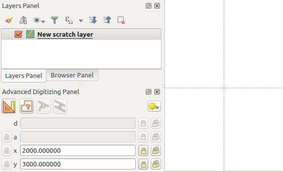
Fig. 12.99 Comece a desenhar nas coordenadas fornecidas
You can proceed as above, adding a new set of coordinates for the next vertex, or switch to another mode of digitizing (e.g. segment, curve or stream).
Se você quiser desenhar um segmento de um determinado comprimento:
Click the d (distance) text box (keyboard shortcut D)
Digite o valor da distância (em unidades do mapa)
Press Enter or click the
button on the right to
lock the mouse in the map canvas to the length of the segment.
In the map canvas, the latest vertex is surrounded by a circle whose
radius is the value entered in the distance text box.
A cross on the circle shows the position of the next vertex if you click.
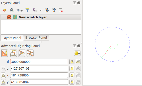
Fig. 12.100 Fixed length segment
Você também pode restringir a posição do vértice, definindo o ângulo do segmento. Conforme descrito anteriormente:
Click the a (angle) text box (keyboard shortcut A)
Digite o valor do ângulo (em graus)
Press Enter or click the
button on the right to lock it.
A line going through the latest vertex and rotated based on the set angle
appears in the map canvas and a cross on it shows the next vertex
position if you click.
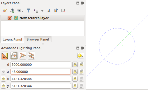
Fig. 12.101 Fixed angle segment
Dica
Pressing Ctrl+<key> or Alt+<key> automatically locks
the target property and puts its value into edit. Modify, press Enter
and you are done. Combined with the Toggle floater,
this can be a real time saver, with keyboard digitizing.
12.3.7.4. Relative reference digitizing
Instead of using absolute values of angles or coordinates, you can also use values relative to the last digitized vertex or segment.
For angles, you can click the  button on the left of the a
text box (or press Shift+A) to toggle relative angles to the previous
segment. With that option on, angles are measured between the last segment
and the mouse pointer.
button on the left of the a
text box (or press Shift+A) to toggle relative angles to the previous
segment. With that option on, angles are measured between the last segment
and the mouse pointer.
For coordinates, click the buttons to the left of the x,
y, z or m text boxes (or press Shift+<key>)
to toggle relative coordinates to the previous vertex. With these options on,
coordinates measurement will consider the last vertex to be the origin of
the set coordinates.
12.3.7.5. Continuous lock
Both in absolute or relative reference digitizing, angle, distance, X, Y, Z
and M constraints can be locked continuously by clicking the  Continuous lock buttons. Using continuous lock allows you to
digitize several points or vertices using the same constraints.
Continuous lock buttons. Using continuous lock allows you to
digitize several points or vertices using the same constraints.
12.3.7.6. Modo de construção
You can enable and disable construction mode by clicking on the
Construction mode icon or with the C keyboard
shortcut. While in construction mode, clicking the map canvas won’t add new
vertices, but will capture the clicks’ positions so that you can use them as
reference points to then lock distance, angle or X, Y, Z, M relative values.
In the Construction mode you will find a drop-down menu
where you can choose to:
- Record Construction Guides: All construction steps are
rendered as dashed lines. Each step that you perform is visually represented,
allowing you to trace the construction process. The guides are displayed as
long as Advanced Digitizing remains active.
- Show Construction Guides: Allows you to make construction
guides visible or hidden on the canvas. When enabled, all active guides are displayed,
offering better spatial orientation and precision during the digitizing process.
- Snap to Visible Construction Guides: The guides are snap-able,
allowing you to start new construction steps from any point along the existing guides.
Choose Clear Construction Guides to remove all the guides from the canvas.
Como exemplo, o modo de construção pode ser usado para desenhar algum ponto a uma distância exata de um ponto existente.
With an existing point in the map canvas and the snapping mode correctly
activated, you can easily draw other points at given distances and angles from
it. In addition to the button, you have to activate also the
construction mode by clicking the Construction mode
icon or with the C keyboard shortcut.
Click next to the point from which you want to calculate the distance and click on the d box (D shortcut) type the desired distance and press Enter to lock the mouse position in the map canvas:
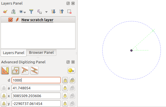
Fig. 12.102 Distância do ponto
Before adding the new point, press C to exit the construction mode. Now, you can click on the map canvas, and the point will be placed at the distance entered.
You can also use the angle constraint to, for example, create another point at
the same distance of the original one, but at a particular angle from the newly
added point. Click the Construction mode icon or with the
C keyboard shortcut to enter construction mode. Click the recently added
point, and then the other one to set a direction segment. Then, click on the
d text box (D shortcut) type the desired distance and press
Enter. Click the a text box (A shortcut) type the
angle you want and press Enter. The mouse position will be locked both in
distance and angle.
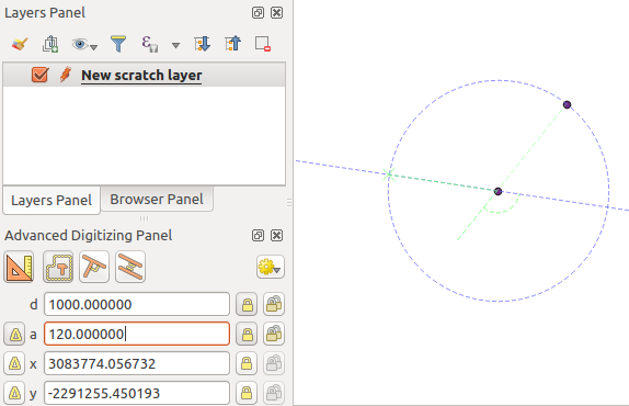
Fig. 12.103 Distância e ângulo dos pontos
Before adding the new point, press C to exit the construction mode. Now, you can click on the map canvas, and the point will be placed at the distance and angle entered. Repeating the process, several points can be added.
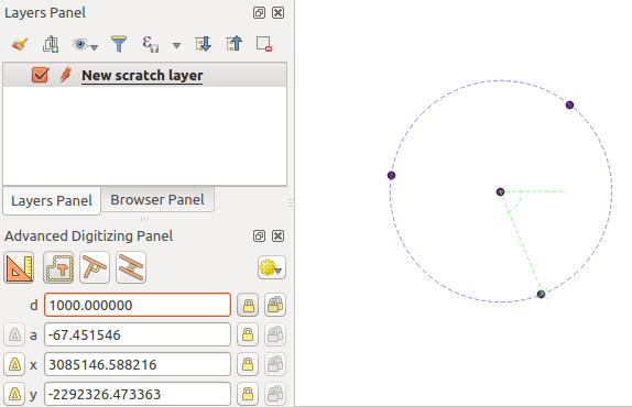
Fig. 12.104 Pontos a uma dada distância e ângulo
12.3.7.7. Linhas paralelas e perpendiculares
All the tools described above can be combined with the
Perpendicular and Parallel tools. These two tools
allow drawing segments perfectly perpendicular or parallel to another segment.
The target segment can be on another layer, another feature within the layer or
the feature being digitized (requires self-snapping option).
Para desenhar um segmento perpendicular:
Primeiro adicione um dos vértices do segmento.
Click the
Perpendicular icon
(keyboard shortcut P) to activate it.Clique no segmento ao qual você deseja ser perpendicular.
A virtual dotted line perpendicular to the segment through the previous vertex appears. The angle property is locked, constraining the next vertex on that line and, a cross indicates the projected position of the cursor on the line. Click to place the new vertex.
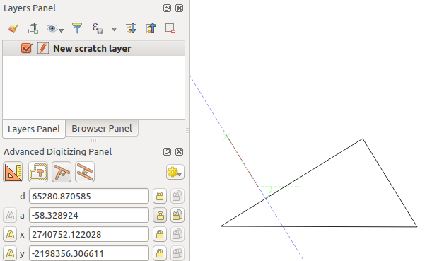
Fig. 12.105 Digitalização perpendicular
To draw a parallel segment, the steps are the same except that you need to
click on the Parallel icon (keyboard shortcut P twice).
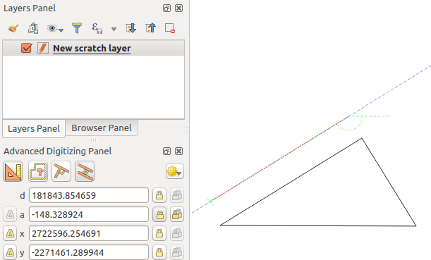
Fig. 12.106 Digitalização paralela
Essas duas ferramentas apenas encontram o ângulo certo do ângulo perpendicular e paralelo e bloqueiam esse parâmetro durante sua edição. Desbloqueie o parâmetro ângulo para cancelar seu uso no meio do processo.
12.3.7.8. 2-circle point intersection
To add a vertex at the intersection of two circles, follow these steps:
Click the
2-circle Point Intersection icon.A dialog will open where you can define the parameters for Circle #1 and Circle #2.
Click on the map canvas, and the tool will automatically calculate the X and Y coordinates for the centers of both circles.
Enter the distance d for each circle.
The tool will calculate and display the two intersection points of the circles.
Click one of the intersection points to add the new vertex.
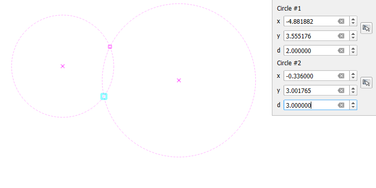
Fig. 12.107 2-circle Point Intersection
12.3.8. The Processing in-place layer modifier
The Processing menu provides access to a large set of tools to analyze and create new features based on the properties of the input features or their relations with other features (within the same layer or not). While the common behavior is to create new layers as outputs, some algorithms also allow modifications to the input layer. This is a handy way to automate multiple features modification using advanced and complex operations.
Para editar feições no local:
Select the layer to edit in the Layers panel.
Selecione as feições em questão. Você pode pular esta etapa, nesse caso a modificação será aplicada a toda a camada.
Press the
 Edit Features In-Place button at the top
of the Processing toolbox. The list of algorithms
is filtered, showing only those compatible with in-place modifications, i.e.:
Edit Features In-Place button at the top
of the Processing toolbox. The list of algorithms
is filtered, showing only those compatible with in-place modifications, i.e.:Eles funcionam na origem da feição e não no nível da camada.
Eles não alteram a estrutura da camada, por ex. adicionando ou removendo campos.
Eles não alteram o tipo de geometria, por ex. de camada de linha para ponto.

Fig. 12.108 Algoritmos de processamento: todos (esquerda) vs editores de polígonos no local (direita)
Encontre o algoritmo que deseja executar e clique duas vezes nele.
Nota
Se o algoritmo não precisar de nenhum parâmetro adicional definido pelo usuário (excluindo os parâmetros usuais da camada de entrada e saída), o algoritmo será executado imediatamente sem nenhum pop-up de diálogo.
Se forem necessários parâmetros diferentes das camadas usuais de entrada ou saída, a caixa de diálogo do algoritmo será exibida. Preencha as informações necessárias.
Click Modify Selected Features or Modify All Features depending on whether there’s an active selection.
Changes are applied to the layer and placed in the edit buffer: the layer is indeed toggled to editing mode with unsaved modification as indicated by the
 icon next to the layer name.
As usual, press
Save layer edits to commit the changes in
the layer. You can also press Undo to rollback the whole
modification.