12.4. Creating 3D Symbols
The Style Manager helps you create and store 3D symbols for every geometry type to render in the 3D map view.
As of the other items, enable the  3D Symbols tab and expand the
  button menu to create:
12.4.1. Point Layers
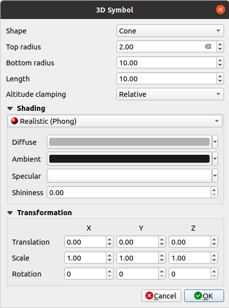
Fig. 12.24 Properties of a 3D point symbol
You can define different simple 3D shapes like Sphere, Cylinder, Cube, Cone, Plane and Torus defined by their Radius, Size or Length. The unit of size of the 3D shapes refers to the CRS of the project.
The shading of the 3D shapes can be defined by the menus Diffuse, Ambient, Specular and Shininess (see https://en.wikipedia.org/wiki/Phong_reflection_model#Description)
If you choose 3D Model, the location will be determined by a simple point coordinate.
For visualizing 3D point clouds you can use Billboard Shapes defined by the Billboard Height, Billboard symbol and Altitude clamping. The symbol will have a stable size.
Altitude clamping can be set to Absolute, Relative or Terrain. The Absolute setting can be used when height values of the 3d vectors are provided as absolute measures from 0. Relative and Terrain add given elevation values to the underlying terrain elevation.
Translation can be used to move objects in x, y and z axis.
You can define a Scale factor for the 3D shape as well as a Rotation around the x-, y- and z-axis.
12.4.2. Line layers
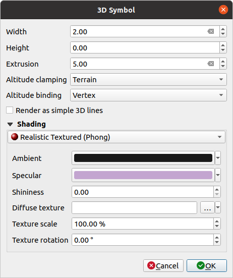
Fig. 12.25 Properties of a 3D line symbol
Beneath the Width and Height settings you can define the Extrusion of the vector lines. If the lines do not have z-values, you can define the 3d volumes with this setting.
With the Altitude clamping you define the position of the 3D lines relative to the underlying terrain surface, if you have included raster elevation data or other 3D vectors.
The Altitude binding defines how the feature is clamped to the terrain. Either every Vertex of the feature will be clamped to the terrain or this will be done by the Centroid.
It is possible to
 Render as simple 3D lines.
The shading can be defined in the menus Diffuse, Ambient, Specular and Shininess.
12.4.3. Polygon Layers
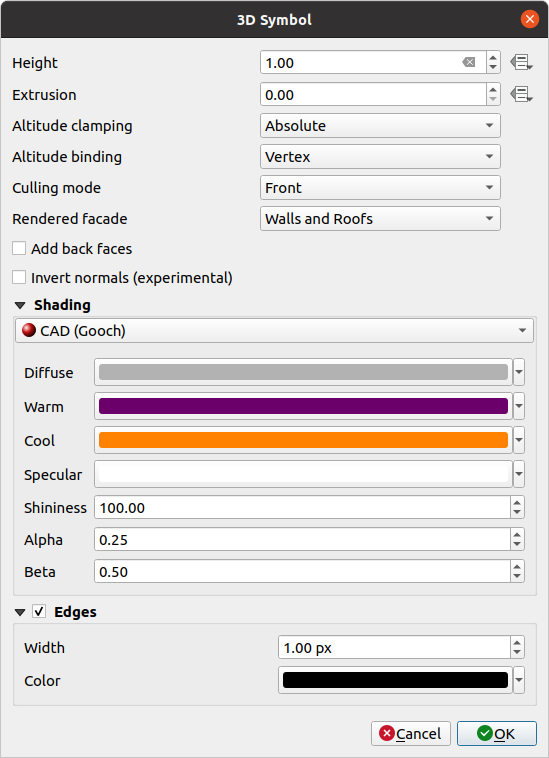
Fig. 12.26 Properties of a 3D polygon symbol
As for the other ones, Height can be defined in CRS units. You can also use the
 button to overwrite the value with a custom
expression, a variable or an entry of the attribute table
button to overwrite the value with a custom
expression, a variable or an entry of the attribute tableAgain, Extrusion is possible for missing z-values. Also for the extrusion you can use the
button in order to use the values of
the vector layer and have different results for each polygon: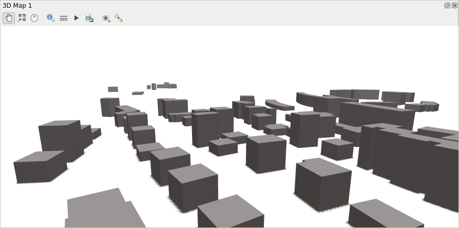
Fig. 12.27 Data Defined Extrusion
The Altitude clamping, Altitude binding can be defined as explained above.
There is an additional option to
Add back faces
and Invert normals.You can define
Edges by Width and Color.
12.4.4. Application example
To go through the settings explained above you can have a look at https://public.cloudmergin.com/projects/saber/luxembourg/tree.