23.5. The model designer
The model designer allows you to create complex models using a simple and easy-to-use interface. When working with a GIS, most analysis operations are not isolated, rather part of a chain of operations. Using the model designer, that chain of operations can be wrapped into a single process, making it convenient to execute later with a different set of inputs. No matter how many steps and different algorithms it involves, a model is executed as a single algorithm, saving time and effort.
The model designer can be opened from the Processing menu ().
23.5.1. The model designer interface
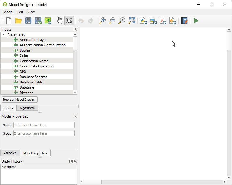
Fig. 23.18 Model designer
In its main part, the modeler has a working canvas where the structure of the model and the workflow it represents can be constructed.
At the top of the dialog, different menus and the Navigation toolbar give access to a variety of tools.
23.5.1.1. Model menu
Label |
Shortcut |
Navigation Toolbar |
Description |
|---|---|---|---|
|
Checks whether the algorithms and inputs used in the model exist. Convenient before releasing a model. |
||
|
F5 |
|
Executes the model |
|
Shift+F5 |
Runs only the selected steps in a model, allowing to run a subset of the model |
|
Reorder Model Inputs… |
Sets the order in which inputs are presented to the user in the algorithm dialog. |
||
Reorder Output Layers… |
Sets a specific order which the outputs from the model must use when loading the results into a project. |
||
|
Ctrl+O |
|
Opens a |
|
Ctrl+S |
|
Saves the model to disk as a |
|
Ctrl+Shift+S |
|
Saves the model to disk as a new |
|
|
Embeds the model file in the project file, making it available when sharing the project file. |
|
|
|
An interface to document the model, the algorithms, the parameters and outputs, as well as the author and versioning |
|
|
|
Saves the model’s graphical design to an image file format (for illustration purpose) |
|
|
Saves the model’s graphical design to a |
||
|
Saves the model’s graphical design to an |
||
|
|
Generates a python script file including the model’s instructions |


23.5.1.2. Edit menu
Label |
Shortcut |
Navigation Toolbar |
Description |
|---|---|---|---|
|
Ctrl+A |
Selects all the model components in the designer |
|
Snap selected components to Grid |
snaps and aligns the elements into a grid |
||
|
Ctrl+Y |
|
Rollback the latest canceled action. See also the Undo/Redo panel. |
|
Ctrl+Z |
|
Cancel the previous change. See also the Undo/Redo panel. |
|
Ctrl+X |
Cuts a selection of components from the model. |
|
|
Ctrl+C |
Copies a selection of components from the model. |
|
|
Ctrl+V |
Pastes a cut or copied selection of components from a model to another or within the same model. The selected components keep their original properties and comments. |
|
|
Del |
Removes a component from the model. |
|
Add Group Box |
Adds a box at the background of related components in order to visually group them. Particularly useful in big models to keep the workflow clean. |


23.5.1.3. View menu
Label |
Shortcut |
Navigation Toolbar |
Description |
|---|---|---|---|
Zooms to the selected group box extent |
|||
|
Ctrl++ |
|
|
|
Ctrl+- |
|
|
|
Ctrl+1 |
|
|
|
Ctrl+0 |
|
Displays all the components in the designer current canvas |
|
Displays comments associated to every algorithm or input in the model designer |
||
|
|||
|
Ctrl+Tab |
Switches ON or OFF the panels in the designer |


23.5.1.4. Panels
The left part of the window is a section with five panels that can be used to add new elements to the model:
Inputs: all the input parameters that could shape your model
Toolbox: here you can find available Processing algorithms. It also includes input parameters. Use Search… box to find algorithms or inputs.
Model Properties: specify the name (required) of the model and the group in which it will be displayed in the Processing Toolbox
Variables: Models can contain dedicated variables that are unique and only available to them. These variables can be accessed by any expression used within the model. They are useful to control algorithms within a model and control multiple aspects of the model by changing a single variable. The variables can be viewed and modified in the Variables panel.
Undo History: this panel will register everything that happens in the modeler, making it easy to cancel things you did wrong.
23.5.1.5. About available algorithms
Some algorithms that can be executed from the do not appear in the list of available algorithms when you are designing a model. To be included in a model, an algorithm must have the correct semantic. If an algorithm does not have such a well-defined semantic (for instance, if the number of output layers cannot be known in advance), then it is not possible to use it within a model, and it will not appear in the list of algorithms that you can find in the modeler dialog. On the other hand some algorithms are specific to the modeler. Those algorithms are located within the group ‘Modeler Tools’.
23.5.2. Creating a model
Creating a model involves two basic steps:
Definition of necessary inputs. These inputs will be added to the parameters window, so the user can set their values when executing the model. The model itself is an algorithm, so the parameters window is generated automatically as for all algorithms available in the Processing framework.
Definition of the workflow. Using the input data of the model, the workflow is defined by adding algorithms and selecting how they use the defined inputs or the outputs generated by other algorithms in the model.
23.5.2.1. Definition of inputs
The first step is to define the inputs for the model. They are found in the Inputs panel on the left side of the modeler window. Hovering with the mouse over the inputs will show a tooltip with additional information. For a full list of available parameters in modeler and their correspondence for scripting, please read Input and output types for Processing Algorithms.
When double-clicking on an element, a dialog is shown that lets you define its characteristics. Depending on the parameter, the dialog will contain at least one element (the description, which is what the user will see when executing the model). For example, when adding a numerical value, as can be seen in the next figure, in addition to the description of the parameter, you have to set a default value and the range of valid values.
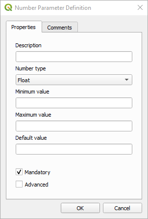
Fig. 23.19 Model Parameters Definition
You can define your input as mandatory for your model by checking the

Mandatory option and by checking the 
Advanced
checkbox you can set the input to be within the Advanced section. This is
particularly useful when the model has many parameters and some of them are not
trivial, but you still want to choose them.
For each added input, a new element is added to the modeler canvas.

Fig. 23.20 Model Parameters
You can also add inputs by dragging the input type from the list and dropping it at the position where you want it in the modeler canvas. If you want to change a parameter of an existing input, just double click on it, and the same dialog will pop up.
When using a model within another model, the inputs and outputs necessary will be displayed in the canvas.
23.5.2.2. Definition of the workflow
In the following example we will add two inputs and two algorithms. The aim of
the model is to copy the elevation values from a DEM raster layer to a line layer
using the Drape algorithm, and then calculate the total ascent of the line
layer using the Climb Along Line algorithm.
In the Inputs tab, choose the two inputs as Vector Layer for the line and
Raster Layer for the DEM.
We are now ready to add the algorithms to the workflow.
Algorithms can be found in the Toolbox panel, grouped much in the same way as they are in the Processing toolbox.
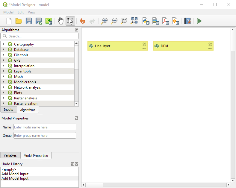
Fig. 23.21 Model Inputs
To add an algorithm to a model, double-click on its name or drag and drop it, just like for inputs.
As for the inputs you can change the description of the algorithm and add a comment.
When adding an algorithm, an execution dialog will appear, with a content similar
to the one found in the execution panel that is shown when executing the algorithm from the toolbox.
The following picture shows both the Drape (set Z value from raster)
and the Climb along line algorithm dialogs.
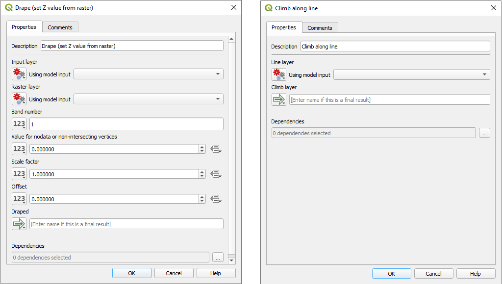
Fig. 23.22 Model Algorithm parameters
As you can see, there are however some differences. Each parameter has a drop-down menu next to it allowing to control how it will be served during the workflow:
 Value: allows you to assign a static value to the parameter.
Depending on the parameter type, the widget will let you enter a number (
Value: allows you to assign a static value to the parameter.
Depending on the parameter type, the widget will let you enter a number (5.0), a string (mytext), select layer(s) loaded in the QGIS project or from a folder, pick items from a list, … Pre-calculated Value: opens the Expression Builder dialog
and lets you define an expression to fill the parameter.
Model inputs together with some other layer statistics are available as variables
and are listed at the top of the Search dialog of the Expression Builder.
The expression is evaluated once before the child algorithm is executed
and used during the execution of that algorithm.
Pre-calculated Value: opens the Expression Builder dialog
and lets you define an expression to fill the parameter.
Model inputs together with some other layer statistics are available as variables
and are listed at the top of the Search dialog of the Expression Builder.
The expression is evaluated once before the child algorithm is executed
and used during the execution of that algorithm. Model Input: allows to use an input added to the model as a parameter.
Once clicked, this option will list all the suitable inputs for the parameter.
Model Input: allows to use an input added to the model as a parameter.
Once clicked, this option will list all the suitable inputs for the parameter. Algorithm Output:
allows to use the output of another algorithm as an input of the current algorithm.
As of model inputs, this option will list all the suitable inputs for the parameter.
Algorithm Output:
allows to use the output of another algorithm as an input of the current algorithm.
As of model inputs, this option will list all the suitable inputs for the parameter.The output parameter also has the above options in its drop-down menu:
add static outputs for child algorithms, e.g. always saving a child algorithm’s output to a predefined geopackage or postgres layer
use an expression based output values for child algorithms, e.g. generating an automatic file name based on today’s date and saving outputs to that file
use a model input, e.g. the File/Folder model input to specify an output file or folder
use another algorithm output, e.g. the output of the Create directory algorithm (from Modeler tools)
an additional
 Model Output option makes the output of the algorithm available in the model.
If a layer generated by the algorithm is only to be used as input to another algorithm,
don’t edit that text box.
Model Output option makes the output of the algorithm available in the model.
If a layer generated by the algorithm is only to be used as input to another algorithm,
don’t edit that text box.
In the following picture you can see the two input parameters defined as
Model Inputand the temporary output layer: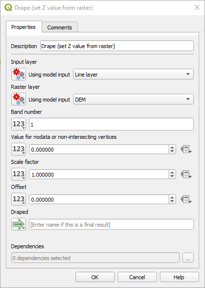
Fig. 23.23 Algorithm Input and Output parameters
You will also find an additional parameter named Dependencies that is not available when calling the algorithm from the toolbox. This parameter allows you to define the order in which algorithms are executed, by explicitly defining one algorithm as a parent of the current one. This will force the parent algorithm to be executed before the current one.
When you use the output of a previous algorithm as the input of your algorithm, that implicitly sets the previous algorithm as parent of the current one (and places the corresponding arrow in the modeler canvas). However, in some cases an algorithm might depend on another one even if it does not use any output object from it (for instance, an algorithm that executes a SQL sentence on a PostgreSQL database and another one that imports a layer into that same database). In that case, just select the previous algorithm in the Dependencies parameter and they will be executed in the correct order.
Once all the parameters have been assigned valid values, click on OK and the algorithm will be added to the canvas. It will be linked to the elements in the canvas (algorithms or inputs) that provide objects that are used as inputs for the algorithm.
Elements can be dragged to a different position on the canvas using the
 Select/Move/Link Item tool.
This is useful to make the structure of the model clearer and more intuitive.
You can also resize the elements, grasping their border.
This is particularly useful if the description of the input or algorithm is long.
With option checked, items resizing
or displacement can be bound to a virtual grid, for a more visually structured
algorithm design.
Select/Move/Link Item tool.
This is useful to make the structure of the model clearer and more intuitive.
You can also resize the elements, grasping their border.
This is particularly useful if the description of the input or algorithm is long.
With option checked, items resizing
or displacement can be bound to a virtual grid, for a more visually structured
algorithm design.
Links between elements are updated automatically and you can see a + button
at the top and at the bottom of each algorithm. Clicking the button will list
all the inputs and outputs of the algorithm so you can have a quick overview.
You can create or remove connections between model components using an interactive drag-and-drop interface. Each parameter and algorithm item on the model canvas includes small circular sockets, output sockets on the right and input sockets on the left. To connect components, click and drag from an output socket (either from a model input or an algorithm) to an input socket on another algorithm. A visual edge follows the cursor and completes the connection when released. To remove a connection, drag the edge away from the input socket. The algorithm dialogs update automatically to reflect changes made using the drag-and-drop interface.
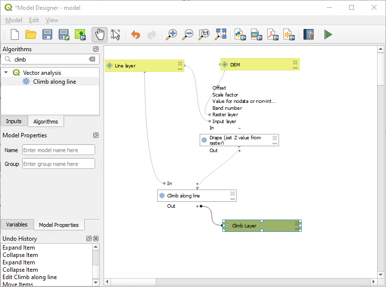
Fig. 23.24 A complete model
With the tool, you can add a draggable box to the canvas. This feature is very useful in big models to group related elements in the modeler canvas and to keep the workflow clean. For example we might group together all the algorithms of the example:
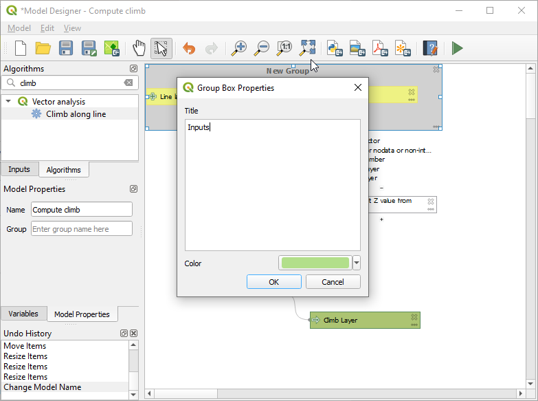
Fig. 23.25 Model Group Box
You can change the name and the color of the boxes. Group boxes are very useful when used together with tool, allowing you to zoom to a specific part of the model. You can also zoom in and out by using the mouse wheel.
You might want to change the order of the inputs and how they are listed in the
main model dialog. At the bottom of the Input panel you will find the
Reorder Model Inputs... button and by clicking on it a new dialog pops up
allowing you to change the order of the inputs:
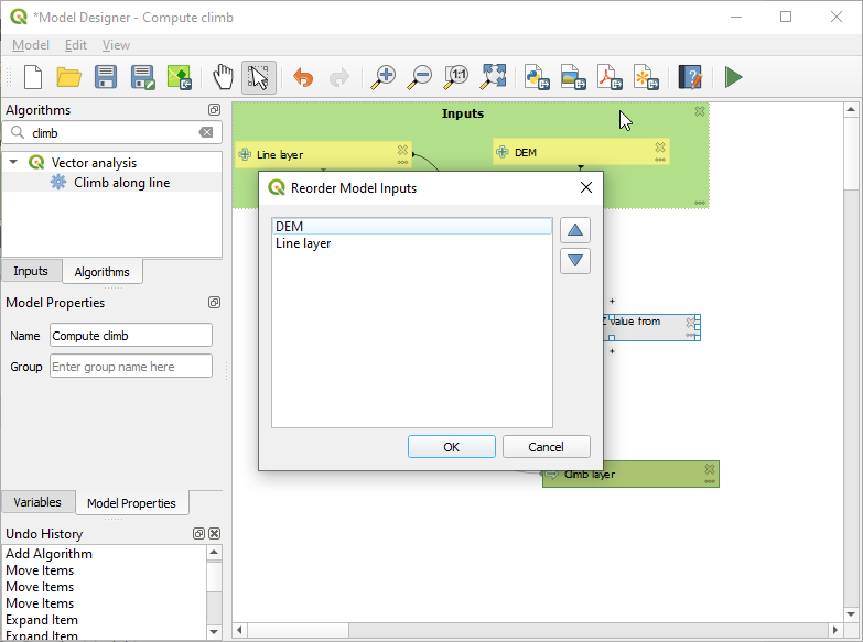
Fig. 23.26 Reorder Model Inputs
There is also the possibility to set a specific order which the outputs from
the model must use when loading the results into a project. This gives the model
creator a means of ensuring that layers are logically ordered on the canvas when
running a model, such as placing a vector layer output over a raster layer output,
or a point layer over a polygon layer.
The model creator can also set an optional “Group name” for the outputs for
automatically grouping outputs within the layer tree using a new group name or by
adding them to an existing group.
In the Model menu you will find the Reorder Output Layers... entry and by
clicking on it a new dialog pops up allowing you to change the order of the output
layers:
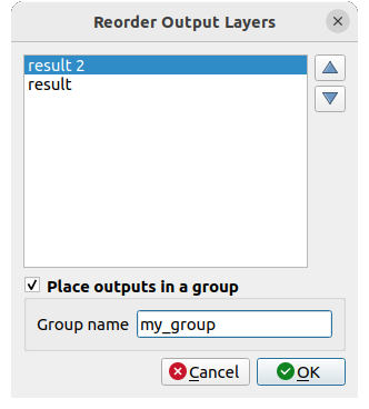
Fig. 23.27 Reorder Output Layers
Comments can also be added to inputs or algorithms present in the modeler. This can be done by going in the Comment tab of the item or with a right-click. In the same tab a color can be set manual for individual model comments. Comments are visible only in the modeler canvas and not in the final algorithm dialog; they can be hidden by deactivating .
Your model can be run in various ways:
You can run the whole model by clicking on
 Run Model… from the toolbar,
right-clicking on the model in the Browser panel
or :
when using the editor to execute a model, any non-default values will be saved in the inputs.
This means that executing the model at a later time from the editor
will have the dialog prefilled with those values on any subsequent run.
Run Model… from the toolbar,
right-clicking on the model in the Browser panel
or :
when using the editor to execute a model, any non-default values will be saved in the inputs.
This means that executing the model at a later time from the editor
will have the dialog prefilled with those values on any subsequent run.You can select elements of the model and run only that subset of the model: press the
 Run Selected Steps… option
from the menu or from the contextual menu of a selected algorithm.
The initial state will be taken from any previous executions of the model through the editor,
so results from previous steps in the model are available for the selected steps.
This makes it possible to fix parts of a large model,
without having to constantly run the entire model to test.
Especially useful when earlier steps in the model are time consuming.
Run Selected Steps… option
from the menu or from the contextual menu of a selected algorithm.
The initial state will be taken from any previous executions of the model through the editor,
so results from previous steps in the model are available for the selected steps.
This makes it possible to fix parts of a large model,
without having to constantly run the entire model to test.
Especially useful when earlier steps in the model are time consuming.You can run a subset of the model, starting from a specific algorithm: right-click the algorithm and select
Run from Here….
Likewise, values are taken from previous executions.In order to use the algorithm from the Processing Toolbox, it has to be saved and the modeler dialog closed, to allow the toolbox to refresh its contents.
23.5.2.3. Documenting your model
You need to document your model, and this can be done from the modeler itself.
Click on the  Edit model help button, and a
dialog like the one shown next will appear.
Edit model help button, and a
dialog like the one shown next will appear.
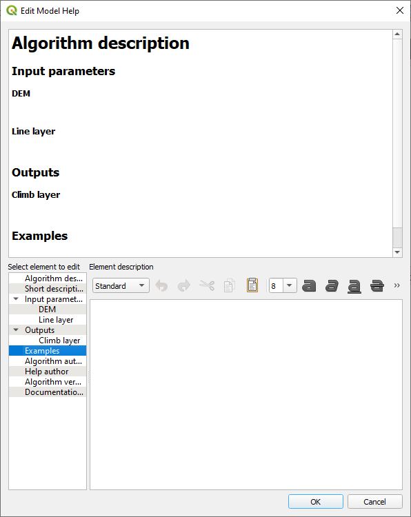
Fig. 23.28 Editing Help
On the right-hand side, you will see a simple HTML page, created using the description of the input parameters and outputs of the algorithm, along with some additional items like a general description of the model or its author. Also, there is an Example section where you can input your own custom examples to help explain the usage of the model. The first time you open the help editor, all these descriptions are empty, but you can edit them using the elements on the left-hand side of the dialog. Select an element on the upper part and then write its description in the text box below.
Model help is saved as part of the model itself.
23.5.3. Saving and loading models
23.5.3.1. Saving models
Use the  Save model button to save the current model and the
 Open Model button to open a previously saved model.
Models are saved with the
Open Model button to open a previously saved model.
Models are saved with the .model3 extension.
If the model has already been saved from the modeler window,
you will not be prompted for a filename.
Since there is already a file associated with the model, that file
will be used for subsequent saves.
Before saving a model, you have to enter a name and a group for it in the text boxes in the upper part of the window.
Models saved in the models folder (the default folder when you
are prompted for a filename to save the model) will appear in the
toolbox in the corresponding branch.
When the toolbox is invoked, it searches the models folder for
files with the .model3 extension and loads the models they
contain.
Since a model is itself an algorithm, it can be added to the toolbox
just like any other algorithm.
Models can also be saved within the project file using the
 Save model in project button.
Models saved using this method won’t be written as
Save model in project button.
Models saved using this method won’t be written as .model3 files
on the disk but will be embedded in the project file.
Project models are available in the
 Project models menu of the toolbox and in
the menu item.
Project models menu of the toolbox and in
the menu item.
The models folder can be set from the Processing configuration dialog, under the Modeler group.
Models loaded from the models folder appear not only in the
toolbox, but also in the algorithms tree in the Algorithms
tab of the modeler window.
That means that you can incorporate a model as a part of a bigger model,
just like other algorithms.
Models will show up in the Browser panel and can be run from there.
23.5.3.2. Exporting a model as a Python script
As we will see in a later chapter, Processing algorithms can be called from the QGIS Python console, and new Processing algorithms can be created using Python. A quick way to create such a Python script is to create a model and then export it as a Python file.
To do so, click on the  Export as Script Algorithm…
in the modeler canvas or right click on the name of the model in the Processing
Toolbox and choose Export Model as Python Algorithm….
Export as Script Algorithm…
in the modeler canvas or right click on the name of the model in the Processing
Toolbox and choose Export Model as Python Algorithm….
23.5.3.3. Exporting a model as an image, PDF or SVG
A model can also be exported as an image, SVG or PDF (for illustration
purposes) by clicking  Export as image,
 Export as PDF or
  Export as SVG.
23.5.4. Editing a model
You can edit the model you are currently creating, redefining the workflow and the relationships between the algorithms and inputs that define the model.
You can also edit existing model from the Browser panel choosing Edit Model… option.
If you right-click on an algorithm in the canvas, you will see a context menu like the one shown next:
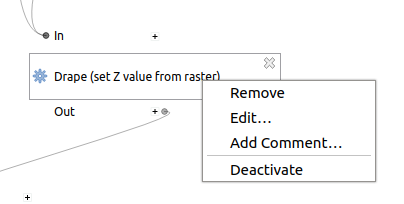
Fig. 23.29 Modeler Right Click
Options for running part of the model have been exposed earlier.
Selecting the Remove option will cause the selected algorithm to be removed. An algorithm can be removed only if there are no other algorithms depending on it. That is, if no output from the algorithm is used as input in a different one.
Selecting the Edit… option will show the parameter dialog so you can change the inputs and parameter values. Not all input elements available in the model will appear as available inputs. Layers or values generated at a more advanced step in the workflow defined by the model will not be available if they cause circular dependencies.
Select the new values and click on the OK button as usual. The connections between the model elements will change in the modeler canvas accordingly.
The Add comment… allows you to add a comment to the algorithm to better describe the behavior.
Note
Right-clicking an input parameter will also allow you to Remove, Edit… and Add comment…
A model can be run partially by deactivating some of its algorithms. To do it, select the Deactivate option in the context menu that appears when right-clicking on an algorithm element. The selected algorithm, and all the ones in the model that depend on it will be displayed in grey and will not be executed as part of the model.
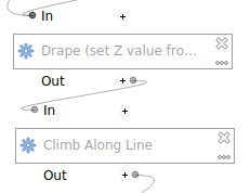
Fig. 23.30 Model with a deactivated algorithm
When right-clicking on an algorithm that is not active, you will see an Activate menu option that you can use to reactivate it.
When editing a model through the designer (and after having run that model), right-clicking any child step in the model allows to select
 View Output Layers.
This will add the output layers from that step as new layers in the current QGIS project.
View Output Layers.
This will add the output layers from that step as new layers in the current QGIS project.This action is available for all child algorithms in the model, even if the model is not configured to use the outputs from those children as model outputs. This is designed as a helpful debugging action. If a model fails (or gives unexpected results), you can then trace through the model and view the outputs for suspected problematic steps. It avoids the need to add temporary outputs to a model and re-run to test.
Additionally, this action is always available after running the model, even if the model itself failed (e.g., because of a misconfigured step later in the model).
The View Log action helps you see the log for each child algorithm after you’ve closed down the algorithm dialog.