` `
Editando
- Configurando a Tolerância de Atracção e Raio de Pesquisa
- Edição Topológica
- Digitalizar uma camada existente
- Digitalização Avançada
- Retroceder e Retomar
- Rodar Elemento(s)
- Simplificar elemento
- Adicionar Parte
- Apagar Parte
- Adicionar Anel
- Preenchimento Anel
- Apagar Anel
- Refazer elementos
- Curvas de Afastamento
- Dividir Elementos
- Dividindo partes
- Juntar elementos selecionados
- Juntar os atributos dos elementos selecionados
- Rodar Símbolos de Pontos
- Offset Point Symbols
- Automatic Tracing
- The Advanced Digitizing panel
QGIS supports various capabilities for editing OGR, SpatiaLite, PostGIS, MSSQL Spatial and Oracle Spatial vector layers and tables.
Nota
O procedimento para editar camadas do GRASS é diferente - consulte a seção Digitalizando e editando uma camada vetorial GRASS para mais detalhes.
Dica
Edições Simultâneas
This version of QGIS does not track if somebody else is editing the same feature at the same time as you are. The last person to save its edits wins.
Configurando a Tolerância de Atracção e Raio de Pesquisa
For an optimal and accurate edit of the vector layer geometries, we need to set an appropriate value of snapping tolerance and search radius for features vertices.
Tolerância de Atração
Snapping tolerance is the distance QGIS uses to search for the closest vertex and/or segment you are trying to connect to when you set a new vertex or move an existing vertex. If you aren’t within the snapping tolerance, QGIS will leave the vertex where you release the mouse button, instead of snapping it to an existing vertex and/or segment. The snapping tolerance setting affects all tools that work with tolerance.
- A general, project-wide snapping tolerance can be defined by choosing
Settings ‣
 Options...,
Digitizing tab.
You can select between ‘To vertex’, ‘To segment’ or ‘To vertex and segment’
as default snap mode. You can also define a default snapping tolerance and
a search radius for vertex edits. The tolerance can be set either in map
units or in pixels. The advantage of choosing pixels is that the snapping
tolerance doesn’t have to be changed after zoom operations. In our small
digitizing project (working with the Alaska dataset), we define the
snapping units in feet. Your results may vary, but something on the order
of 300 ft at a scale of 1:10000 should be a reasonable setting.
Options...,
Digitizing tab.
You can select between ‘To vertex’, ‘To segment’ or ‘To vertex and segment’
as default snap mode. You can also define a default snapping tolerance and
a search radius for vertex edits. The tolerance can be set either in map
units or in pixels. The advantage of choosing pixels is that the snapping
tolerance doesn’t have to be changed after zoom operations. In our small
digitizing project (working with the Alaska dataset), we define the
snapping units in feet. Your results may vary, but something on the order
of 300 ft at a scale of 1:10000 should be a reasonable setting. - A layer-based snapping tolerance that overrides the global snapping options
can be defined by choosing Settings ‣ Snapping options.
It enables and adjusts snapping mode
and tolerance on a layer basis (see figure_edit_snapping ). This dialog offers
three different modes to select the layer(s) to snap to:
- Current layer: only the active layer is used, a convenient way to ensure topology within the layer being edited
- All layers: a quick and simple setting for all visible layers in the project so that the pointer snaps to all vertices and/or segments. In most cases it is sufficient to use this snapping mode.
- Advanced: if you need to edit a layer and snap its vertices to another layer, ensure the target layer is checked and increase the snapping tolerance to a greater value. Furthermore, snapping will never occur to a layer that is not checked in the snapping options dialog, regardless of the global snapping tolerance. So be sure to mark the checkbox for those layers that you need to snap to.
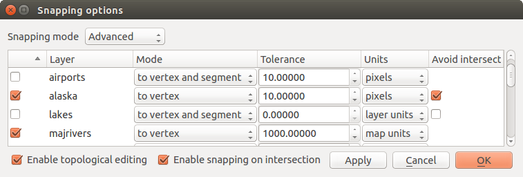
Edit snapping options on a layer basis (Advanced mode)
Dica
Control the list of layers to snap
The Snapping Options dialog is by default populated with parameters (mode, tolerance, units) set in the global Digitizing tab. To avoid layers being checked by default in the Advanced mode and hence set snappable, define the Default Snap mode to Off.
Snapping tolerance can be set in pixels or map units (the units of the map view). While in the Advanced layer selection mode, it is possible to use a snapping tolerance that refers to layer units, the units of the reprojected layer when ‘on-the-fly’ CRS transformation is on.
Raio de pesquisa
Search radius is the distance QGIS uses to search for the closest vertex
you are trying to select when you click on the map. If you aren’t within the
search radius, QGIS won’t find and select any vertex for editing.
The search radius for vertex edits can be defined under Settings ‣
Options ‣ Digitizing tab. This is the same
place where you define the general, project-wide snapping tolerance.
Snap tolerance and search radius are set in map units or pixels, so you may find you need to experiment to get them set right. If you specify too big of a tolerance, QGIS may snap to the wrong vertex, especially if you are dealing with a large number of vertices in close proximity. Set search radius too small, and it won’t find anything to move.
Edição Topológica
Besides layer-based snapping options, you can also define topological
functionalities in the Snapping options... dialog in the
Settings (or File) menu. Here, you can
define  Enable topological editing, and/or for polygon
layers, activate the Avoid Intersections option.
Enable topological editing, and/or for polygon
layers, activate the Avoid Intersections option.
Ativar edição topológica
The option Enable topological editing is for editing
and maintaining common boundaries in features mosaics. QGIS ‘detects’
shared boundary by the features, so you only have to move a common vertex/segment
once, and QGIS will take care of updating the neighboring features.
Evitar intersecções de novos polígonos
A second topological option called Avoid intersections
prevents you to draw new features that overlap an existing one.
It is for quicker digitizing of adjacent
polygons. If you already have one polygon, it is possible with this option
to digitize the second one such that both intersect, and QGIS then cuts the
second polygon to the boundary of the existing one. The advantage is that you
don’t have to digitize all vertices of the common boundary.
Nota
If the new geometry is totally covered by existing ones, it gets cleared and the new feature will have no geometry when allowed by the provider, otherwise saving modifications will make QGIS pop-up an error message.
Aviso
Use cautiously the Avoid Intersections option
Because the option cuts or clears geometry of any overlaping feature from any polygon layer, do not forget to uncheck this option once you no longer need it otherwise, you can get unexpected geometries.
Activar atracção nas intersecções
Outra opção é usar |caixa| :guilabel: Habilitar encaixe em intersecção. Ele permite que você encaixe em uma intersecção de camadas de fundo, mesmo se não há nenhum vértice na interseção.
Verificador de Geometria
A core plugin can help the user to find the geometry invalidity. You can find more information on this plugin at Complemento Verificador de Geometria.
Digitalizar uma camada existente
By default, QGIS loads layers read-only. This is a safeguard to avoid accidentally editing a layer if there is a slip of the mouse. However, you can choose to edit any layer as long as the data provider supports it (see Exploring Data Formats and Fields), and the underlying data source is writable (i.e., its files are not read-only).
Dica
Restrict edit permission on layers within a project
From the Project ‣ Project properties ‣ Identify tab, You can choose to set any layer read-only regardless the provider permission. This can be a handy way, in a multi-users environment to avoid unauthorized users to mistakenly edit layers (e.g., shapefile), hence potentially corrupt data. Note that this setting only applies inside the current project.
In general, tools for editing vector layers are divided into a digitizing and an advanced digitizing toolbar, described in section Digitalização Avançada. You can select and unselect both under View ‣ Toolbars ‣. Using the basic digitizing tools, you can perform the following functions:
Ícone |
Finalidade |
Ícone |
Finalidade |
|---|---|---|---|
 |
Edições actuais |
 |
Alternar edição |
 |
Add Feature: Capture Point |  |
Add Feature: Capture Line |
 |
Add Feature: Capture Polygon |  |
Move Feature |
 |
Add Circular String |  |
Add Circular String By Radius |
 |
Node Tool |  |
Apagar Selecionados |
 |
Cortar Elementos |
 |
Copiar Elementos |
 |
Colar Elementos |
 |
Salvar edições da camada |
Edição da Tabela: Edição básica da camada vectorial pela barra de ferramentas
Note that while using any of the digitizing tools, you can still zoom or pan in the map canvas without losing the focus on the tool.
All editing sessions start by choosing the Toggle editing
option found in the context menu of a given layer, from the attribute table dialog, the
digitizing toolbar or the Edit menu.
Once the layer is in edit mode, additional tool buttons on the editing toolbar will become available and markers will appear at the vertices of all features unless Show markers only for selected features option under Settings ‣ Options... ‣ Digitizing menu is checked.
Dica
Salvar Regularmente
Remember to Save Layer Edits regularly. This will also
check that your data source can accept all the changes.
Adicionando Elementos
You can use the Add Feature,
Add Feature or
Add Feature icons on the toolbar to add new feature (point, line and
polygon) into the current layer.
The next buttons Add circular string or
Add circular string by radius allow users to add
line or polygon features with a circular geometry.
To create features with these tools, you first digitize the geometry then enter its attributes. To digitize the geometry, left-click on the map area to create the first point of your new feature.
For linear or curved geometries, keep on left-clicking for each additional point you wish to capture or use automatic tracing capability to accelerate the digitization. You can switch back and forth between linear Add feature tool and curved Add circular string... tools to create compound curved geometry. Pressing Delete or Backspace key reverts the last node you add. When you have finished adding points, right-click anywhere on the map area to confirm you have finished entering the geometry of that feature.
Nota
Curved geometries are stored as such only in compatible data provider
Although QGIS allows to digitize curved geometries within any editable data format, you need to be using a data provider (e.g. PostGIS, GML or WFS) that supports curves to have features stored as curved, otherwise QGIS segmentizes the circular arcs. The memory layer provider also supports curves.
Dica
Customize the digitizing rubber band
While capturing polygon, the by-default red rubber band can hide underlying features or places you’d like to capture a point. This can be fixed by setting a lower opacity (or alpha channel) to the rubber band’s Fill Color in Settings ‣ Options ‣ Digitizing menu. You can also avoid the use of the rubber band by checking Don’t update rubber band during node editing.
The attribute window will appear, allowing you to enter the information for the new feature. Figure_edit_values shows setting attributes for a fictitious new river in Alaska. However, in the Digitizing menu under the Settings ‣ Options menu, you can also activate:
- Suppress attributes pop-up windows after each created
feature to avoid the form opening
- or Reuse last entered attribute values to have fields
automatically filled at the opening of the form and just have to type changing values.
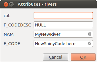
Enter Attribute Values Dialog after digitizing a new vector feature
With the Move Feature(s) icon on the toolbar, you can
move existing features.
Node Tool
For shapefile-based or MapInfo layers as well as SpatiaLite, PostgreSQL/PostGIS,
MSSQL Spatial, and Oracle Spatial tables, the
Node Tool provides manipulation capabilities of
feature vertices similar to CAD programs. It is possible to simply select
multiple vertices at once and to move, add or delete them altogether.
The node tool also works with ‘on the fly’ projection turned on and supports
the topological editing feature. This tool is, unlike other tools in
QGIS, persistent, so when some operation is done, selection stays
active for this feature and tool.
It is important to set the property Settings ‣
Options ‣ Digitizing ‣ Search Radius:
 to a number greater than zero. Otherwise, QGIS will
not be able to tell which vertex is being edited and will display a warning.
to a number greater than zero. Otherwise, QGIS will
not be able to tell which vertex is being edited and will display a warning.
Dica
Marcadores de Vértice
The current version of QGIS supports three kinds of vertex markers:
‘Semi-transparent circle’, ‘Cross’ and ‘None’. To change the marker style,
choose Options from the
Settings menu, click on the Digitizing
tab and select the appropriate entry.
Operações Básicas
Start by activating the Node Tool and selecting a
feature by clicking on it. Red boxes will appear at each vertex of this feature.
- Selecting vertices: You can select vertices by clicking on them one at a time, by clicking on an edge to select the vertices at both ends, or by clicking and dragging a rectangle around some vertices. When a vertex is selected, its color changes to blue. To add more vertices to the current selection, hold down the Ctrl key while clicking. Hold down Ctrl when clicking to toggle the selection state of vertices (vertices that are currently unselected will be selected as usual, but also vertices that are already selected will become unselected).
- Adding vertices: To add a vertex, simply double click near an edge and a new vertex will appear on the edge near to the cursor. Note that the vertex will appear on the edge, not at the cursor position; therefore, it should be moved if necessary.
- Deleting vertices: Select the vertices and click the
Delete key. Deleting all the vertices of a feature generates, if
compatible with the datasource, a geometryless feature. Note that
this doesn’t delete the complete feature, just the geometry part;
To delete a complete feature use the Delete Selected tool.
- Moving vertices: Select all the vertices you want to move, click on a selected vertex or edge and drag in the direction you wish to move. All the selected vertices will move together. If snapping is enabled, the whole selection can jump to the nearest vertex or line.
Each change made with the node tool is stored as a separate entry in the Undo dialog. Remember that all operations support topological editing when this is turned on. On-the-fly projection is also supported, and the node tool provides tooltips to identify a vertex by hovering the pointer over it.
Dica
Move features with precision
The Move Feature tool doesn’t currently allow to
snap features while moving. Using the Node Tool, select ALL
the vertices of the feature, click a vertex, drag and snap it to a target vertex:
the whole feature is moved and snapped to the other feature.
The Vertex Editor
With activating the Node Tool on a feature, QGIS opens the Vertex Editor panel listing all the vertices of the feature with their x, y (z, m if applicable) coordinates and r (for the radius, in case of circular geometry). Simply select a row in the table does select the corresponding vertex in the map canvas, and vice versa. Simply change a coordinate in the table and your vertex position is updated. You can also select multiple rows and delete them altogether.
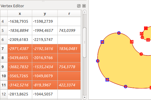
Vertex editor panel showing selected nodes
Cortando, Copiando e Colando Elementos
Selected features can be cut, copied and pasted between layers in the same
QGIS project, as long as destination layers are set to
Toggle editing beforehand.
Dica
Transform polygon into line and vice-versa using copy/paste
Copy a line feature and paste it in a polygon layer: QGIS pastes in the target layer a polygon whose boundary corresponds to the closed geometry of the line feature. This is a quick way to generate different geometries of the same data.
Features can also be pasted to external applications as text. That is, the features are represented in CSV format, with the geometry data appearing in the OGC Well-Known Text (WKT) format. WKT and GeoJSON features from outside QGIS can also be pasted to a layer within QGIS.
When would the copy and paste function come in handy? Well, it turns out that you can edit more than one layer at a time and copy/paste features between layers. Why would we want to do this? Say we need to do some work on a new layer but only need one or two lakes, not the 5,000 on our big_lakes layer. We can create a new layer and use copy/paste to plop the needed lakes into it.
Como exemplo, vamos copiar alguns lagos para uma nova camada:
Carregue a camada que quer copiar a partir (camada de origem)
Carregue ou crie a camada que quer copiar para (camada de destino)
Começar a editar a camada de destino
Ative a camada de origem clicando nela na legenda
- Use the
 Select Features by area or single click
tool to select the feature(s) on the source layer
Select Features by area or single click
tool to select the feature(s) on the source layer - Click on the Copy Features tool
Ative a camada de destino clicando na legenda
- Click on the Paste Features tool
Parar a edição e salvar as alterações
What happens if the source and target layers have different schemas (field names and types are not the same)? QGIS populates what matches and ignores the rest. If you don’t care about the attributes being copied to the target layer, it doesn’t matter how you design the fields and data types. If you want to make sure everything - the feature and its attributes - gets copied, make sure the schemas match.
Nota
Congruência dos Elementos Colados
If your source and destination layers use the same projection, then the pasted features will have geometry identical to the source layer. However, if the destination layer is a different projection, then QGIS cannot guarantee the geometry is identical. This is simply because there are small rounding-off errors involved when converting between projections.
Dica
Copy string attribute into another
If you have created a new column in your attribute table with type ‘string’ and want to paste values from another attribute column that has a greater length the length of the column size will be extended to the same amount. This is because the GDAL Shapefile driver starting with GDAL/OGR 1.10 knows to auto-extend string and integer fields to dynamically accommodate for the length of the data to be inserted.
Apagando os Elementos Selecionados
If we want to delete an entire feature (attribute and geometry), we can do that
by first selecting the geometry using the regular Select
Features by area or single click tool. Selection can also be done from the attribute
table. Once you have the selection set, press Delete or Backspace
key or use the Delete Selected tool to delete the
features. Multiple selected features can be deleted at once.
The Cut Features tool on the digitizing toolbar can
also be used to delete features. This effectively deletes the feature but
also places it on a “spatial clipboard”. So, we cut the feature to delete.
We could then use the Paste Features tool to put it back,
giving us a one-level undo capability. Cut, copy, and paste work on the
currently selected features, meaning we can operate on more than one at a time.
Salvando as Camadas Editadas
When a layer is in editing mode, any changes remain in the memory of QGIS.
Therefore, they are not committed/saved immediately to the data source or disk.
If you want to save edits to the current layer but want to continue editing
without leaving the editing mode, you can click the
Save Layer Edits button. When you turn editing mode off with
Toggle editing (or quit QGIS for that matter),
you are also asked if you want to save your changes or discard them.
If the changes cannot be saved (e.g., disk full, or the attributes have values that are out of range), the QGIS in-memory state is preserved. This allows you to adjust your edits and try again.
Dica
Integridade dos dados
It is always a good idea to back up your data source before you start editing. While the authors of QGIS have made every effort to preserve the integrity of your data, we offer no warranty in this regard.
Saving multiple layers at once
This feature allows the digitization of multiple layers. Choose
 Save for Selected Layers to save all changes you
made in multiple layers. You also have the opportunity to
Save for Selected Layers to save all changes you
made in multiple layers. You also have the opportunity to
 Rollback for Selected Layers, so that the
digitization may be withdrawn for all selected layers.
If you want to stop editing the selected layers,
Rollback for Selected Layers, so that the
digitization may be withdrawn for all selected layers.
If you want to stop editing the selected layers,  Cancel
for Selected Layer(s) is an easy way.
Cancel
for Selected Layer(s) is an easy way.
As mesmas funções estão disponíveis para a edição de todas as camadas do projeto.
Dica
Use transaction group to edit, save or rollback multiple layers changes at once
When working with layers from the same PostGreSQL database, activate the Automatically create transaction groups where possible option in Project ‣ Project Properties ‣ Data Sources to sync their behavior (enter or exit the edit mode, save or rollback changes at the same time).
Digitalização Avançada
Ícone |
Finalidade |
Ícone |
Finalidade |
|---|---|---|---|
 |
Enable Advanced Digitizing Tools |  |
Enable Tracing |
 |
Retroceder |
 |
Retomar |
 |
Rodar Elemento(s) |
 |
Simplificar elemento |
 |
Adicionar Anel |
 |
Adicionar Parte |
 |
Preenchimento Anel |
||
 |
Apagar Anel |
 |
Apagar Parte |
 |
Curva de Afastamento |
 |
Refazer elementos |
 |
Dividindo partes |
 |
Dividir Elementos |
 |
Juntar Atributos dos Elementos Selecionados |
 |
Juntar Elementos Selecionados |
 |
Rodar Símbolos de Pontos |
 |
Offset Point Symbols |
Tabela de edição avançada: Barra de ferramentas de edição avançada de camadas vetoriais
Retroceder e Retomar
The Undo and Redo tools allows you to undo or redo
vector editing operations. There is also a dockable widget, which shows all
operations in the undo/redo history (see Figure_edit_undo). This widget is not
displayed by default; it can be displayed by right-clicking on the toolbar and
activating the Undo/Redo Panel checkbox. The Undo/Redo capability
is however active, even if the widget is not displayed.
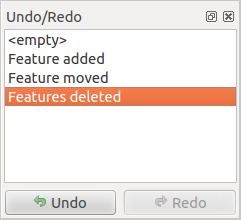
Redo and Undo digitizing steps
When Undo is hit or Ctrl+Z (or Cmd+Z) pressed, the state of all features and attributes are reverted to the state before the reverted operation happened. Changes other than normal vector editing operations (for example, changes done by a plugin) may or may not be reverted, depending on how the changes were performed.
Para usar a tela histórico de desfazer / refazer, basta clicar para selecionar uma operação na lista de histórico. Todas as feições serão revertidas para o estado em que estavam depois da operação selecionada.
Rodar Elemento(s)
Use Rotate Feature(s) to rotate one or multiple features
in the map canvas. Press the Rotate Feature(s) icon and then
click on the feature to rotate. Either click on the map to place the rotated feature or
enter an angle in the user input widget. If you want to rotate several features,
they shall be selected first.
If you enable the map tool with feature(s) selected, its (their) centroid appears and will be the rotation anchor point. If you want to move the anchor point, hold the Ctrl button and click on the map to place it.
If you hold Shift before clicking on the map, the rotation will be done in 45 degree steps, which can be modified afterwards in the user input widget.
To abort feature rotation, you need to click on Rotate
Feature(s) icon.
Simplificar elemento
The Simplify Feature tool allows you to reduce the
number of vertices of a feature, as long as the geometry remains valid. With the
tool you can also simplify many features at once or multi-part features.
First, click on the feature or drag a rectangle over the features. A dialog where you can define a tolerance in map units, layer units or pixels pops up and a colored and simplified copy of the feature(s), using the given tolerance, appears over them. QGIS calculates the amount of vertices that can be deleted while maintaining the geometry. The higher the tolerance is the more vertices can be deleted. When the expected geometry fits your needs just click the [OK] button. The tolerance you used will be saved when leaving a project or when leaving an edit session. So you can go back to the same tolerance the next time when simplifying a feature.
To abort feature simplification, you need to click on
Simplify Feature icon.
Nota
Unlike the feature simplification option in Settings ‣
Options ‣ Rendering menu which simplifies the geometry just for rendering,
the Simplify Feature tool permanently modifies
feature’s geometry in data source.
Adicionar Parte
You can Add Part to a selected feature generating a
multipoint, multiline or multipolygon feature. The new part must be digitized
outside the existing one which should be selected beforehand.
The Add Part can also be used to add a geometry to a geometryless
feature. First, select the feature in the attribute table and digitize the new
geometry with the Add Part tool.
Apagar Parte
The Delete Part tool allows you to delete parts from
multifeatures (e.g., to delete polygons from a multi-polygon feature). This
tool works with all multi-part geometries: point, line and polygon. Furthermore,
it can be used to totally remove the geometric component of a feature.
To delete a part, simply click within the target part.
Adicionar Anel
You can create ring polygons using the
Add Ring icon in the toolbar. This means that inside an existing area, it
is possible to digitize further polygons that will occur as a ‘hole’, so
only the area between the boundaries of the outer and inner polygons remains
as a ring polygon.
Preenchimento Anel
You can use the Fill Ring function to add a ring to
a polygon and add a new feature to the layer at the same time. Using this tool,
you simply have to digitize a polygon within an existing one. Thus you need not
first use the Add Ring icon and then the
Add feature function anymore.
Apagar Anel
The Delete Ring tool allows you to delete rings within
an existing polygon, by clicking inside the hole. This tool only works with
polygon and multi-polygon features. It doesn’t
change anything when it is used on the outer ring of the polygon.
Refazer elementos
You can reshape line and polygon features using the
Reshape Features tool on the toolbar. For lines, it replaces the line
part from the first to the last intersection with the original line.
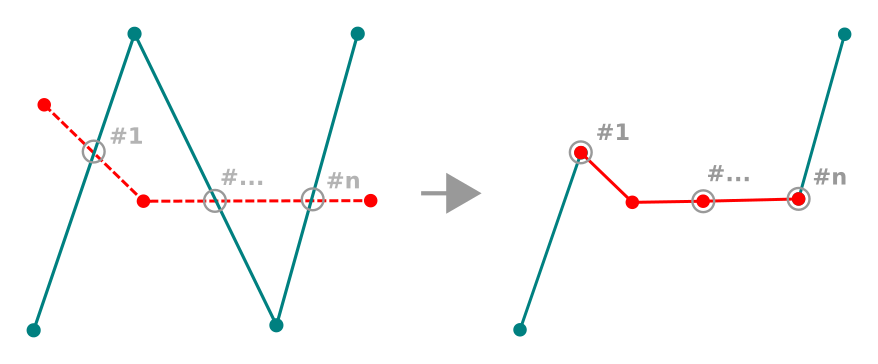
Reshape line
Dica
Extend linestring geometries with reshape tool
Use the Reshape Features tool to extend existing linestring
geometries: snap to the first or last vertex of the line and draw a new one.
Validate and the feature’s geometry becomes the combination of the two lines.
For polygons, it will reshape the polygon’s boundary. For it to work, the reshape tool’s line must cross the polygon’s boundary at least twice. To draw the line, click on the map canvas to add vertexes. To finish it, just right-click. Like with the lines, only the segment between the first and the last intersections is considered. The reshape line’s segments that are inside the polygon will result in cropping it, where the ones outside the polygon will extend it.
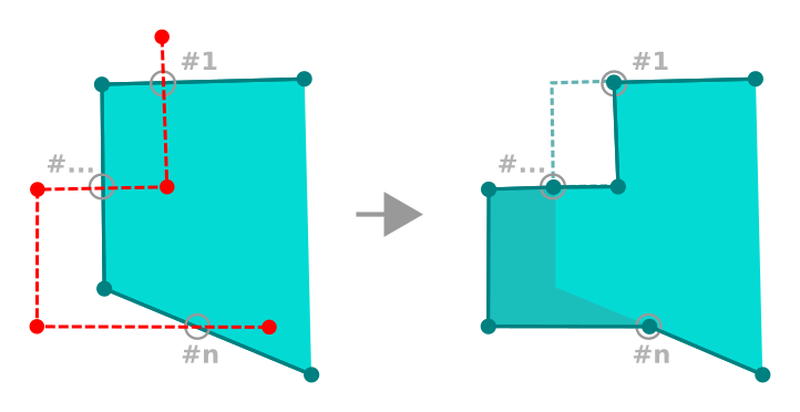
Reshape polygon
With polygons, reshaping can sometimes lead to unintended results. It is mainly useful to replace smaller parts of a polygon, not for major overhauls, and the reshape line is not allowed to cross several polygon rings, as this would generate an invalid polygon.
Nota
A ferramenta de mudança de forma pode alterar a posição inicial de um anel ou de uma linha poligonal fechada. Assim, o ponto que está representada ‘duas vezes’ não será o mesmo mais. Isto pode não ser um problema para a maioria das aplicações, mas é algo a considerar.
Curvas de Afastamento
The Offset Curve tool creates parallel shifts of line layers.
The tool can be applied to the edited layer (the geometries are modified)
or also to background layers (in which case it creates copies of the lines /
rings and adds them to the edited layer).
It is thus ideally suited for the creation of distance line layers.
The User Input dialog pops-up, showing the displacement distance.
To create a shift of a line layer, you must first go into editing mode and activate the
Offset Curve tool. Then click on a feature to shift it.
Move the mouse and click where wanted or enter the desired distance in the user
input widget. Your changes may then be saved with the Save Layer Edits tool.
QGIS options dialog (Digitizing tab then Curve offset tools section) allows you to configure some parameters like Join style, Quadrant segments, Miter limit.
Dividir Elementos
You can split features using the Split Features
icon on the toolbar. Just draw a line across the feature you want to split.
Dividindo partes
In QGIS it is possible to split the parts of a multi part feature so that the
number of parts is increased. Just draw a line across the part you want to split using
the Split Parts icon.
Dica
Split a polyline feature in one-click
A single click on a snapped vertex of a line feature with the
Split Features or Split Parts tool is enough to have it
split into new features or parts.
Juntar elementos selecionados
The Merge Selected Features tool allows you to create
a new feature by merging existing ones: their geometries are merged to generate
a new one. If features don’t have common boundaries,
a multipolygon/multipolyline/multipoint feature is created.
First, select several features. Then press the Merge Selected
Features button. In the new dialog, you can select at the top of the dialog which value to
apply to each field of the new feature. That value can be:
- picked from the attributes of the initial features,
- an aggregation of the initial features attributes (Minimum, Maximum, Median, Sum, Count Concatenation... depending on the type of the field. see Statistical Summary Panel for the full list of functions),
- skipped, meaning that the field will be empty,
- or manually entered, at the bottom of the rows.
Juntar os atributos dos elementos selecionados
The Merge Attributes of Selected Features tool
allows you to apply same attributes to features without merging their boundaries.
The dialog is the same as the Merge Selected Features tool’s except that
unlike that tool, selected objects are kept with their geometry while some of their
attributes are made identical.
Rodar Símbolos de Pontos
The Rotate Point Symbols allows you to change the rotation
of point symbols in the map canvas. First of all, you must apply to the symbol a
data-defined rotation: in the Layer Properties
‣ Style dialog, click the  Data-defined override widget
near the Rotation option of the highest level (preferably) of the symbol
layers and choose a field in the Field Type combobox. Values of this
field are hence used to rotate each feature’s symbol accordingly.
Data-defined override widget
near the Rotation option of the highest level (preferably) of the symbol
layers and choose a field in the Field Type combobox. Values of this
field are hence used to rotate each feature’s symbol accordingly.
Nota
As a global option, setting the rotation field at the first level of the symbol applies it to all the underlying levels while setting it at a lower level will rotate only this symbol layer (unless you have a single symbol layer).
Rodar Símbolos de Pontos
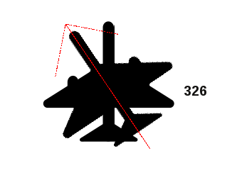
To change the rotation of a symbol, click on a point feature in the map canvas
with the Rotate Point Symbols and move the mouse around,
holding the left button pressed. A red arrow with the rotation value
will be visualized (see Figure_rotate_point). When you release the left mouse
button again, the symbol is defined with this new rotation and the rotation
field is updated in the layer’s attribute table.
Dica
Se segurar a tecla Ctrl premido, a rotação irá ser feita em passos de 15 graus.
Offset Point Symbols
The Offset Point Symbols allows you to interactively
change the rendered position of point symbols in the map canvas. This tool behaves
like the Rotate Point Symbols tool except that it
requires you to connect a field to the data-defined Offset (X,Y)
property of the symbol, field which will then be populated with the offset
coordinates while moving the symbol in the map canvas.
Nota
The Offset Point Symbols tool doesn’t
move the point feature itself; you should use the Node Tool
or Move Feature tool for this purpose.
Aviso
Ensure to assign the same field to all symbol layers
If at least two layers of the symbol have different fields assigned to their data-defined property (e.g. rotation), the corresponding tool will consider that no field is assigned to the symbol property and won’t perform the action.
Automatic Tracing
Usually, when using capturing map tools (add feature, add part, add ring, reshape and split), you need to click each vertex of the feature.
Using the automatic tracing mode you can speed up the digitization process.
Enable the Tracing tool by pushing the icon or pressing
t key and snap to a vertex or segment of a
feature you want to trace along. Move the mouse over another vertex or segment
you’d like to snap and instead of an usual straight line, the digitizing rubber
band represents a path from the last point you snapped to the current position.
QGIS actually uses the underlying features topology to build the shortest path
between the two points. Click and QGIS places the intermediate vertices following
the path. You no longer need to manually place all the vertices during digitization.
Tracing requires snapping to be activated in traceable layers to build the path. You should also snap to an existing vertex or segment while digitizing and ensure that the two nodes are topologically connectable following existing features, otherwise QGIS is unable to connect them and thus traces a single straight line.
Nota
Adjust map scale or snapping settings for an optimal tracing
If there are too many features in map display, tracing is disabled to avoid potentially long tracing structure preparation and large memory overhead. After zooming in or disabling some layers the tracing is enabled again.
Dica
Quickly enable or disable automatic tracing by pressing t key
By pressing t key, tracing can be enabled/disabled anytime even while digitizing one feature, so it is possible to digitize some parts of the feature with tracing enabled and other parts with tracing disabled. Tools behave as usual when tracing is disabled.
The Advanced Digitizing panel
When capturing, reshaping, splitting new or existing geometries you also have the possibility to use the Advanced Digitizing panel. You can digitize lines exactly parallel or perpendicular to a particular angle or lock lines to specific angles. Furthermore, you can enter coordinates directly so that you can make a precise definition of your new geometry.
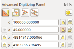
The Advanced Digitizing panel
Nota
As ferramentas não são habilitadas se a visão do mapa está em coordenadas geográficas.
The Advanced Digitizing panel can be open either with a right-click on the
toolbar and choose Advanced Digitizing panel or in View ‣
Panels ‣ Advanced Digitizing Panel. Once the panel is visible, click the
enable advanced digitizing tool button to activate the Advanced
Digitizing tool.
Concepts
The aim of the Advanced Digitizing tool is to lock coordinates, lengths, and angles when moving the mouse during the digitalizing in the map canvas.
You can also create constraints with relative or absolute reference. Relative reference means that the next vertex constraints’ values will be relative to the previous vertex or segment.
Snapping Settings
Click the  button to set the Advanced Digitizing Tool snapping settings.
You can make the tool snap to common angles. The options are:
button to set the Advanced Digitizing Tool snapping settings.
You can make the tool snap to common angles. The options are:
- Do not snap to common angles
- Snap to 30º angles
- Snap to 45º angles
- Snap to 90º angles
You can also control the snapping to features. The options are:
- Do not snap to vertices or segments
- Snap according to project configuration
- Snap to all layers
Keyboard shortcuts
To speed up the use of Advanced Digitizing Panel, there are a couple of keyboard shorcuts available:
| Key | Simple | Ctrl + or Alt + | Shift + |
|---|---|---|---|
| d | Set distance | Lock distance | |
| a | Set angle | Lock angle | Toggle relative angle to last segment |
| x | Set x coordinate | Lock x coordinate | Toggle relative x to last vertex |
| y | Set y coordinate | Lock y coordinate | Toggle relative y to last vertex |
| c | Toggle construction mode | ||
| p | Toggle perpendicular and parallel modes | ||
Absolute reference digitizing
When drawing a new geometry from scratch, it is very useful to have the possibility to start digitizing vertexes at given coordinates.
For example, to add a new feature to a polygonal layer, click the
button. You can choose the X and Y coordinates where you want
to start editing the feature, then:
- Click the x text box (or use the x keyboard shortcuts).
- Type the X coordinate value you want and press Enter or click the
 button to their right to lock the mouse to the X axis on the map
canvas.
button to their right to lock the mouse to the X axis on the map
canvas. - Click the y text box (or use the y keyboard shortcuts).
- Type the Y coordinate value you want and press Enter or click the
button to their right to lock the mouse to the Y axis on the map
canvas.
Two blue dotted lines and a green cross identify the exact coordinates you entered. Start digitizing by clicking on the map canvas; the mouse position is locked at the green cross.
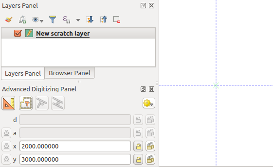
Start drawing at given coordinates
You can continue digitizing by free hand, adding a new pair of coordinates, or you can type the segment’s length (distance) and angle.
If you want to draw a segment of a given length, click the d
(distance) text box (keyboard shortcut d), type the distance value (in
map units) and press Enter or click the button on the right to
lock the mouse in the map canvas to the length of the segment.
In the map canvas, the clicked point is surrounded by a circle whose radius is
the value entered in the distance text box.
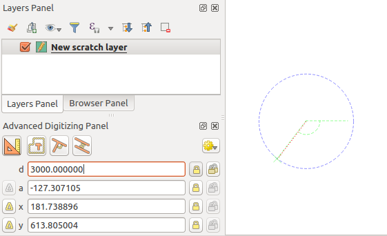
Fixed length segment
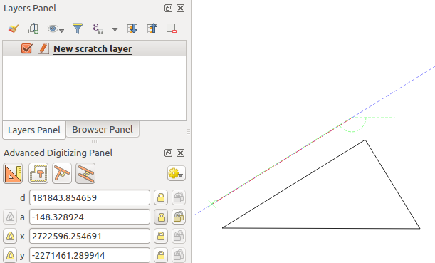
Finally, you can also choose the angle of the segment. As described before ,
click the a (angle) text box (keyboard shortcut a), type the
angle value (in degrees), and press Enter or click the buttons
on the right to lock it. In this way the segment will follow the desired angle:
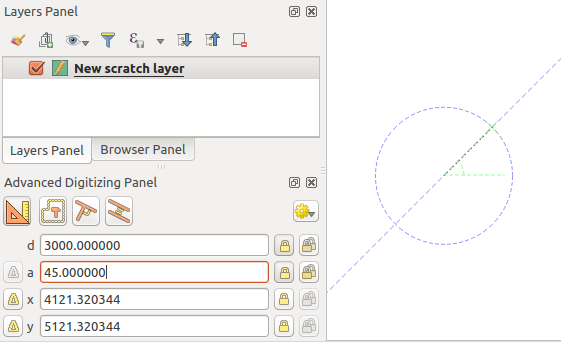
Fixed angle segment
Relative reference digitizing
Instead of using absolute values of angles or coordinates, you can also use values relative to the last digitized vertex or segment.
For angles, you can click the  button on the left of the a
text box (or press Shift + a) to toggle relative angles to the previous
segment. With that option on, angles are measured between the last segment
and the mouse pointer.
button on the left of the a
text box (or press Shift + a) to toggle relative angles to the previous
segment. With that option on, angles are measured between the last segment
and the mouse pointer.
For coordinates, click the buttons to the left of the x or
y text boxes (or press Shift + x or Shift + y) to
toggle relative coordinates to the previous vertex. With these options on,
coordinates measurement will consider the last vertex to be the x and y axes
origin.
Continuous lock
Both in absolute or relative reference digitizing, angle, distance, x and y
constraints can be locked continuously by clicking the  Continuous lock buttons. Using continuous lock allows you to
digitize several points or vertexes using the same constraints.
Continuous lock buttons. Using continuous lock allows you to
digitize several points or vertexes using the same constraints.
Parallel and perpendiculars line
All the tools described above can be combined with the  Perpendicular and
  Parallel tools. These two tools
allow drawing segments perfectly perpendicular or parallel to another segment.
Parallel tools. These two tools
allow drawing segments perfectly perpendicular or parallel to another segment.
To draw a perpendicular segment, during the editing click the
Perpendicular icon (keyboard shortcut p) to
activate it. Before drawing the perpendicular line,
click on the segment of an existing feature that you want to be perpendicular
to (the line of the existing feature will be colored in light orange); you
should see a blue dotted line where your feature will be snapped:
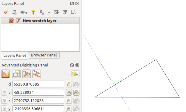
Perpendicular digitizing
To draw a parallel feature, the steps are the same: click on the
Parallel icon (keyboard shortcut p twice), click on
the segment you want to use as reference and start drawing your feature:
Parallel digitizing
These two tools just find the right angle of the perpendicular and parallel angle and lock this parameter during your editing.
Construction mode
You can enable and disable construction mode by clicking on the
 Construction icon or with the c keyboard
shortcut. While in construction mode, clicking the map canvas won’t add new
vertexes, but will capture the clicks’ positions so that you can use them as
reference points to then lock distance, angle or x and y relative values.
Construction icon or with the c keyboard
shortcut. While in construction mode, clicking the map canvas won’t add new
vertexes, but will capture the clicks’ positions so that you can use them as
reference points to then lock distance, angle or x and y relative values.
As an example, the construction mode can be used to draw some point at an exact distance from an existing point.
With an existing point in the map canvas and the snapping mode correctly
activated, you can easily draw other points at given distances and angles from
it. In addition to the button, you have to activate also the
construction mode by clicking the Construction
icon or with the c keyboard shortcut.
Click next to the point from which you want to calculate the distance and click on the d box (d shortcut) type the desired distance and press Enter to lock the mouse position in the map canvas:
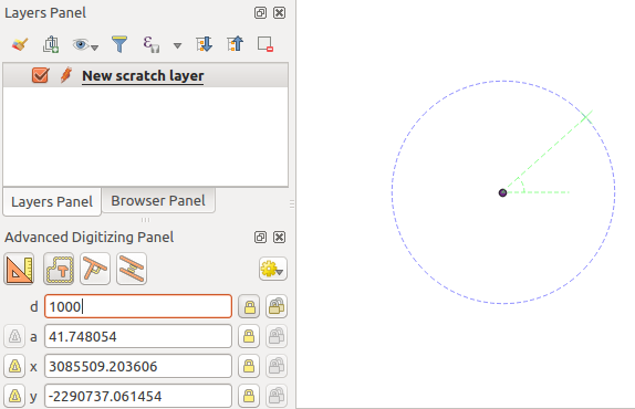
Distance from point
Before adding the new point, press c to exit the construction mode. Now, you can click on the map canvas, and the point will be placed at the distance entered.
You can also use the angle constraint to, for example, create another point at
the same distance of the original one, but at a particular angle from the newly
added point. Click the Construction icon or with the
c keyboard shortcut to enter construction mode. Click the recently added
point, and then the other one to set a direction segment. Then, click on the
d text box (d shortcut) type the desired distance and press
Enter. Click the a text box (a shortcut) type the
angle you want and press Enter. The mouse position will be locked both in
distance and angle.
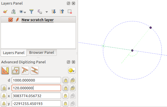
Distance and angle from points
Before adding the new point, press c to exit the construction mode. Now, you can click on the map canvas, and the point will be placed at the distance and angle entered. Repeating the process, several points can be added.
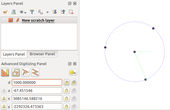
Points at given distance and angle