21.2.10. 图形项
QGIS在打印布局中提供了一系列工具绘制常规或复杂图形
备注
与其他打印布局项不同,你不能自定义框架风格,也不能自定义形状边界的背景颜色(默认设定为透明色)
21.2.10.1. 常规图形项
布局:guilabel:图形 项是一个有助于布置你地图的工具,包含三角形、矩形和椭圆形等常规图形... 你可以使用|addBasicShape|:sup:添加图形 工具来添加一个常规图形,点击该工具集可以访问特定的工具,例如  添加矩形,|addBasicCircle| 添加椭圆 和
  添加三角形.选择了合适的工具之后,你可以根据接下来的:ref:`项目创建指令<create_layout_item>`绘制图形. 和其他布局项一样,常规形状的操作方法和:ref:`interact_layout_item`中提示的操作一样.
备注
在绘制基本图形时要按住:kbd:`Shift`键,使用单击+拖动的方式,可以帮助你创建一个完美的正方形,圆或者三角形.
默认的图形项可以使用它的:guilabel:‘项目属性’面板来定制。除了:ref: ' 项目基本属性<item_common_properties>`,该特性还有以下功能(参见:numref: ' figure_layout_basic_shape '):
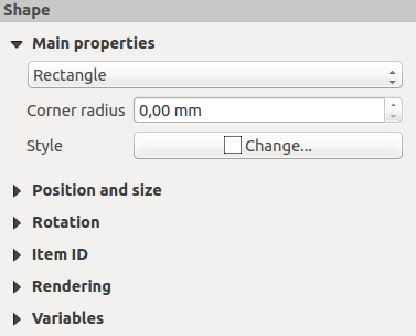
图 21.59 图形项属性面板
主要特性 组中,并在图框中允许你转换形状项的类型 (椭圆, 矩形 or 三角形).
你可以使用高级选择器控件:ref:符号 <symbol-selector> and 颜色 设置形状的样式
对于矩形图形,你可以使用不同的单位来更改:guilabel:圆角半径 设置圆角.
21.2.10.2. 基于结点的形状项
尽管|addBasicShape| 添加形状 工具提供了创建简单和预定义几何项的方式,  :guilabel:`添加结点项`工具帮助你创建一个自定义或更高级的几何项. 对于折线或多边形, 你可以画任意数量的线或者边, 并且项目的顶点可以使用
  :guilabel:`编辑结点项`独立且直接地操作. 项目本身也可以在 :ref:`interact_layout_item`中操作.
添加一个基于结点的形状
单击
添加结点项 图标选择
 添加多边形 或
  添加折线 工具
Perform consecutive left clicks to add nodes of your item. If you hold down the Shift key while drawing a segment, it is constrained to follow an orientation multiple of 45°.
完成绘制后,右键单击,结束图形绘制。
你可以在:guilabel:项目特性 面板自定义形状的外观.
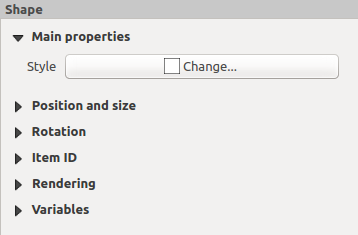
图 21.60 多边形结点形状项目特性面板
在 主要特性`中, 你可以使用高级选择器控件:ref:`符号 <symbol-selector> 和:ref:颜色 <color-selector> 设置样式...
对于折线结点项,你同样可以使用:guilabel:`线路标记`参数化后添加
使用选项开始/结束标记:
无: 绘制一个简单折线
箭头:添加一个自定义箭头指向的常规三角形.
SVG 标记:使用文件:file:SVG 文件作为项目目标.
自定义箭头指向
Arrow stroke color: sets the stroke color of the arrow head.
Arrow fill color: sets the fill color of the arrow head.
Arrow stroke width: sets the stroke width of the arrow head.
Arrow head width: sets the size of the arrow head.
SVG images are automatically rotated with the line. Stroke and fill colors of QGIS predefined SVG images can be changed using the corresponding options. Custom SVG may require some tags following this instruction.
图 21.61 Polyline Node Shape Item Properties Panel
The Arrow Item
The  Add Arrow tool is a shortcut to create an arrow-enabled
polyline by default and thus has the same properties and behavior as a
polyline node item.
Add Arrow tool is a shortcut to create an arrow-enabled
polyline by default and thus has the same properties and behavior as a
polyline node item.
Actually, the arrow item can be used to add a simple arrow, for example, to
show the relation between two different print layout items. However, to create
a north arrow, the image item should be considered
first as it gives access to a set of north arrows in .SVG format that
you can sync with a map item so that it rotates automatically with it.
Editing a node item geometry
A specific tool is provided to edit node-based shapes through
Edit Nodes Item. Within this mode, you can select
a node by clicking on it (a marker is displayed on the selected node). A
selected node can be moved either by dragging it or by using the arrow keys.
Moreover, in this mode, you are able to add nodes to an existing shape:
double-click on a segment and a node is added at the place you click.
Finally, you can remove the currently selected node by
hitting the Del key.