12.3. Editing
QGIS has various capabilities for editing OGR, SpatiaLite, PostgreSQL, MS SQL Server and Oracle Spatial vector layers and tables. They can be of 2D or 3D geometry type.
Note
The procedure for editing GRASS layers is different - see section Digitizing and editing a GRASS vector layer for details.
Attention
Concurrent Edits
QGIS does not track if somebody else is editing the same feature at the same time as you are. The last person to save the edits wins.
Tip
Validating Edits
Continuous validation can be activated on a layer basis in the tab. More at Digitizing Properties.
12.3.1. Setting the snapping tolerance and search radius
Under the menu, QGIS provides a number of parameters to configure default behaviour of editing tools. More information at Digitizing settings.
For optimal and accurate editing of vector layer geometries, we need to set an appropriate value of snapping tolerance and search radius for features vertices. The Snapping group provides related options, namely handling of the snapping tolerance and the search radius.
Snapping tolerance: When you add a new vertex or move an existing one, the snapping tolerance is the distance QGIS uses to search for the closest vertex or segment you are trying to connect to. If you are not within the snapping tolerance, QGIS will leave the vertex where you release the mouse button, instead of snapping it to an existing vertex or segment.
The tolerance setting affects all tools that work with snapping and applies by default to new layers and projects. It can however be overridden at layer level (see Snapping and Digitizing Options).
Search radius: Search radius for vertex edits is the distance QGIS uses to
searchfor the vertex to select when you click on the map. If you are not within the search radius, QGIS will not find and select any vertex for editing.
Snap tolerance and search radius are set in map units or pixels.
You may need to experiment to get them right.
If you specify a too big tolerance, QGIS may snap to the wrong vertex,
especially if you are dealing with a large number of vertices in close
proximity.
The smaller the search radius, the more difficult it will be to hit
what you want to move.
12.3.2. Snapping and Digitizing Options
Global snapping and digitizing settings (snapping mode, tolerance value, and units…) can be overridden in the project from the menu. In the Snapping and Digitizing Options, you can also configure some other properties (snapping layers, scale limit, topology…) The Snapping Toolbar gives access to most of these features.
By default, snapping is disabled in a project until you press the
 Enable snapping button or press S.
The snapping mode, tolerance value, and units can also be configured in
this toolbar.
Enable snapping button or press S.
The snapping mode, tolerance value, and units can also be configured in
this toolbar.
12.3.2.1. Snapping properties
There are three options to select the layer(s) to snap to:
All layers: quick setting for all visible layers in the project so that the pointer snaps to all vertices and/or segments. In most cases, it is sufficient to use this snapping mode, but beware when using it for projects with many vector layers, as it may affect performance.
Current layer: only the active layer is used, a convenient way to ensure topological consistency within the layer being edited.
Advanced Configuration: allows you to enable and adjust snapping mode, tolerance and units, overlaps and scales of snapping on a layer basis (see Fig. 12.82). If you need to edit a layer and snap its vertices to another, make sure that the target layer is checked and increase the snapping tolerance to a higher value. Snapping will not occur to a layer that is not checked in the snapping options dialog.
When moving or creating vertex, you can opt for the following snapping modes:
 Vertex
 Segment: snaps along a line or a polygon perimeter.
If topological editing is enabled, then a new vertex is added at the snapping location.
Segment: snaps along a line or a polygon perimeter.
If topological editing is enabled, then a new vertex is added at the snapping location. Area: guarantees that the snap point lies anywhere on a polygon’s area,
not necessarily on its boundary
Area: guarantees that the snap point lies anywhere on a polygon’s area,
not necessarily on its boundary Centroid: snaps to the centroid of the geometry of a feature.
In case of a multipart geometry, the target point may be distinct from the existing parts.
Centroid: snaps to the centroid of the geometry of a feature.
In case of a multipart geometry, the target point may be distinct from the existing parts. Middle of Segments on line or polygon feature
 Line Endpoints: snaps to the first or last vertex of every part
of a line or polygon feature.
Line Endpoints: snaps to the first or last vertex of every part
of a line or polygon feature.
QGIS will show different snap icons depending on the kind of snap:
Snapping to a vertex: box icon |
Snapping to a segment: hourglass icon |
Snapping to an intersection: cross icon |
Note that it is possible to change the color of these icons in the Digitizing part of the global settings.
The tolerance values can be set either in the project’s map units
or in pixels.
The advantage of choosing pixels is that it keeps the snapping
constant at different map scales.
10 to 12 pixels is normally a good value, but it depends on the DPI of
your screen.
Using map units allows the tolerance to be related to real ground
distances.
For example, if you have a minimum distance between elements, this
option can be useful to ensure that you don’t add vertices too close to
each other.
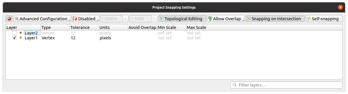
Fig. 12.82 Snapping options (Advanced Configuration mode)
Note
By default, only visible features (the features whose style is displayed,
except for layers where the symbology is “No symbols”) can be snapped.
You can enable the snapping on invisible features by checking  Enable snapping on invisible features under the
tab.
Enable snapping on invisible features under the
tab.
Tip
Enable snapping by default
You can set snapping to be enabled by default on all new projects in the tab. You can also set the default snapping mode, tolerance value, and units, which will populate the Snapping Options dialog.
12.3.2.2. Enable snapping on intersections
Another available option is to use  snapping on
intersection, which allows you to snap to geometry intersections of
snapping enabled layers, even if there are no vertices at the intersections.
snapping on
intersection, which allows you to snap to geometry intersections of
snapping enabled layers, even if there are no vertices at the intersections.
12.3.2.3. Limit snapping to a scale range
In some cases snapping can become very slow. This is often caused by the amount of features in some layers that require a heavy index to compute and maintain. Some parameters exist to enable snapping only when the map view is inside a relevant scale range. This allows to only do the costly index computation related to snapping at a scale where drawing is relevant.
Scale limit to snapping is configured in . Limiting snapping to scale is only available in Advanced Configuration mode.
To limit snapping to a scale range you have three modes available:
Disabled: Snapping is enabled whatever the current map scale is. This is the default mode.
Global: Snapping is limited and only enabled when the current scale of the map is between a global minimum and a global maximum value. When selecting this mode two widgets become available to configure the range of scales in which snapping is enabled.
Per layer: The snapping scale range limit is defined for each layer. When selecting this mode two columns become available to configure the minimum and maximum scales for each layer.
Please note that the minimum and maximum scales follow the QGIS convention: minimum scale is the most “zoomed out” scale while maximum scale is the most “zoomed in”. A minimum or maximum scale that is set to “0” or “not set” is considered not limiting.
12.3.2.4. Self-snapping
The  Self-snapping option allows you to snap to
the geometry that is being edited. Combined with the advanced
digitizing panel, this provides a handy way
to digitize new edges relative to the previous edges or vertices.
Self-snapping can cause invalid geometries, use with caution.
Self-snapping option allows you to snap to
the geometry that is being edited. Combined with the advanced
digitizing panel, this provides a handy way
to digitize new edges relative to the previous edges or vertices.
Self-snapping can cause invalid geometries, use with caution.

Fig. 12.83 Drawing features with self-snapping
12.3.2.5. Snapping on custom grid
A snapping distance can also be customized on a layer basis in the Digitizing tab of the layer properties dialog. With setting the Geometry precision distance, you enable a dotted grid visible when the map canvas is at a coherent scale for display. Snapping can then be performed on the dots of the grid: an added or modified geometry will have all of its vertices snapped automatically to the closest node of the grid. More information at Digitizing Properties.
12.3.3. Topological editing
In addition to these snapping options, the Snapping options… dialog () and the Snapping toolbar allow you to enable / disable some other topological functionalities.
12.3.3.1. Enable topological editing
The  Topological editing button helps
when editing and maintaining features with common boundaries.
With this option enabled, QGIS ‘detects’ shared boundaries.
When you move common vertices/segments, QGIS will also move them in
the geometries of the neighboring features.
Topological editing button helps
when editing and maintaining features with common boundaries.
With this option enabled, QGIS ‘detects’ shared boundaries.
When you move common vertices/segments, QGIS will also move them in
the geometries of the neighboring features.
Topological editing works with features from different layers, as long as the layers are visible and in editing mode.
In layer with Z or M values, topological editing will interpolate the Z or M value of the vertex based on the value of the edge used for the connection.
12.3.3.2. Overlapping control
Overlapping prevents you from drawing new features that overlap existing ones in the selected layer, speeding up digitizing of adjacent polygons. It can be controlled by the overlap tool. Three modes are available:
 Allow Overlap (default)
 Avoid Overlap on Active Layer:
prevents any overlap with other features from the layer being edited.
Digitize the new geometries so that they overlap their neighbours and
QGIS will cut the overlapping part(s) of the new geometries and snap them
to the boundary of the existing features. The advantage is that you don’t
have to digitize the common vertices on boundary.
Avoid Overlap on Active Layer:
prevents any overlap with other features from the layer being edited.
Digitize the new geometries so that they overlap their neighbours and
QGIS will cut the overlapping part(s) of the new geometries and snap them
to the boundary of the existing features. The advantage is that you don’t
have to digitize the common vertices on boundary. Follow Advanced Configuration:
allows the overlapping setting to be set on a layer basis in the
Advanced configuration view mode.
Follow Advanced Configuration:
allows the overlapping setting to be set on a layer basis in the
Advanced configuration view mode.
Note
If the new geometry is totally covered by existing ones, it gets cleared, and QGIS will show an error message.
Warning
Use cautiously the Avoid overlap option
Since this option will cut new overlapping geometries of any polygon layer, you can get unexpected geometries if you forget to uncheck it when no longer needed.
12.3.3.3. Automatic Tracing
Usually, when using capturing map tools (add feature, add part, add ring, reshape and split), you need to click each vertex of the feature. With the automatic tracing mode, you can speed up the digitization process as you no longer need to manually place all the vertices during digitization:
Enable the
 Tracing tool (in the Snapping toolbar)
by pushing the icon or
pressing T key.
Tracing tool (in the Snapping toolbar)
by pushing the icon or
pressing T key.Snap to a vertex or segment of a feature you want to trace along.
Move the mouse over another vertex or segment you’d like to snap and, instead of the usual straight line, the digitizing rubber band represents a path from the last point you snapped to the current position. The tool also works with curved geometries.
QGIS actually uses the underlying features topology to build the shortest path between the two points. Tracing requires snapping to be activated in traceable layers to build the path. You should also snap to an existing vertex or segment while digitizing and ensure that the two nodes are topologically connectable through existing features edges, otherwise QGIS is unable to connect them and thus traces a single straight line.
Click and QGIS places the intermediate vertices following the displayed path.
Unfold the Enable Tracing icon and set the
Offset option to digitize a path parallel to the features
instead of tracing along them.
A positive value shifts the new drawing to the left side of the tracing
direction and a negative value does the opposite.
Note
Adjust map scale or snapping settings for an optimal tracing
If there are too many features in map display, tracing is disabled to avoid potentially long tracing structure preparation and large memory overhead. After zooming in or disabling some layers the tracing is enabled again.
Note
Does not add topological points
This tool does not add points to existing polygon geometries even if Topological editing is enabled. If geometry precision is activated on the edited layer, the resulting geometry might not exactly follow an existing geometry.
Tip
Quickly enable or disable automatic tracing by pressing the T key
By pressing the T key, tracing can be enabled/disabled anytime (even while digitizing a feature), so it is possible to digitize parts of the feature with tracing enabled and other parts with tracing disabled. Tools behave as usual when tracing is disabled.
Tip
Convert tracing to curved geometries
By using you can create curved geometries while digitizing. See digitizing options.
12.3.4. Digitizing an existing layer
By default, QGIS loads layers read-only. This is a safeguard to avoid accidentally editing a layer if there is a slip of the mouse. However, you can choose to edit any layer as long as the data provider supports it (see Exploring Data Formats and Fields), and the underlying data source is writable (i.e., its files are not read-only).
Tip
Restrict edit permission on layers within a project
From the table, you can choose to set any layer read-only regardless the provider permission. This can be a handy way, in a multi-users environment to avoid unauthorized users to mistakenly edit layers (e.g., Shapefile), hence potentially corrupt data. Note that this setting only applies inside the current project.
In general, tools for editing vector layers are divided into a digitizing and an advanced digitizing toolbar, described in section Advanced digitizing. You can select and unselect both under .
Using the basic digitizing tools, you can perform the following functions:
Tool |
Purpose |
Tool |
Purpose |
|---|---|---|---|
|
Access to save, rollback or cancel changes in all or selected layers simultaneously |
|
Turn on or off edit status of selected layer(s) based on the active layer status |
|
Save edits to the active layer |
||
|
Digitize using straight segments |
|
Digitize using curve lines |
|
Enable freehand digitizing |
|
Digitize polygon of regular shape |
|
Add new record |
|
Add Feature: Capture Point |
|
Add Feature: Capture Line |
|
Add Feature: Capture Polygon |
|
Vertex Tool (All Layers) |
|
Vertex Tool (Current Layer) |
|
Set whether the vertex editor panel should auto-open |
|
Modify the attributes of all selected features simultaneously |
|
Delete Selected features from the active layer |
|
Cut Features from the active layer |
|
Copy selected Features from the active layer |
|
Paste Features into the active layer |
|
Undo changes in the active layer |
|
Redo changes in active layer |


Note that while using any of the digitizing tools, you can still zoom or pan in the map canvas without losing the focus on the tool.
All editing sessions start by choosing the  Toggle editing option found in the context menu of a given layer,
from the attribute table dialog, the digitizing toolbar or the
menu.
Toggle editing option found in the context menu of a given layer,
from the attribute table dialog, the digitizing toolbar or the
menu.
Once the layer is in edit mode, additional tool buttons on the editing toolbar will become available and markers will appear at the vertices of all features unless Show markers only for selected features option under menu is checked.
Tip
Save Regularly
Remember to  Save Layer Edits regularly.
This will also check that your data source can accept all the changes.
Save Layer Edits regularly.
This will also check that your data source can accept all the changes.
12.3.4.1. Geometry editing techniques
When a geometry drawing tool (mainly the ones that add, split, reshape features) is enabled for a line or polygon based layer, you can select the technique for adding new vertices:
The
 Digitize with Segment: draws straight segment
whose start and end points are defined by left clicks.
Digitize with Segment: draws straight segment
whose start and end points are defined by left clicks.The
 Digitize with Curve: draws curve line based on
three consecutive nodes defined by left clicks (start, point along the arc, end).
If the geometry type does not support curves, then consecutive smaller segments
are used to approximate the curvature.
Digitize with Curve: draws curve line based on
three consecutive nodes defined by left clicks (start, point along the arc, end).
If the geometry type does not support curves, then consecutive smaller segments
are used to approximate the curvature.The
 Stream Digitizing: draws lines in freehand mode,
i.e. nodes are added following cursor movement in the map canvas and
a Streaming Tolerance.
The streaming tolerance defines the spacing between consecutive vertices.
Currently, the only supported unit is pixels (
Stream Digitizing: draws lines in freehand mode,
i.e. nodes are added following cursor movement in the map canvas and
a Streaming Tolerance.
The streaming tolerance defines the spacing between consecutive vertices.
Currently, the only supported unit is pixels (px). Only the starting left click and the ending right click are necessary in this mode.The
 Digitize Shape: triggers tools on the
Shape Digitizing Toolbar to draw a polygon of a regular shape.
Digitize Shape: triggers tools on the
Shape Digitizing Toolbar to draw a polygon of a regular shape.
The selected technique remains while switching among the digitizing tools. You can combine any of the first three methods while drawing the same geometry.
12.3.4.2. Adding Features
Depending on the layer type, you can use the  Add Record,
 Add Point Feature,
  Add Line Feature
or
Add Line Feature
or  Add Polygon Feature icons on the toolbar to add new
features into the current layer.
Add Polygon Feature icons on the toolbar to add new
features into the current layer.
To add a geometryless feature, click on the Add Record
button and you can enter attributes in the feature form that opens.
To create features with the spatially enabled tools, you first digitize the geometry then enter its attributes. To digitize the geometry:
(Optional as it is the default) Select the
Digitize With Segment geometry drawing methodLeft-click on the map area to create the first point of your new feature. For point features, this should be enough and trigger, if required, the feature form to fill in their attributes.
For line or polygon geometries, keep on left-clicking for each additional point you wish to capture. You can rely on the snapping to features options, the snap-to-grid or the advanced digitizing panel to accurately position each vertex.
Along with drawing straight segments between nodes you click one by one, lines and polygons can be:
traced automatically, accelerating the digitization. This will create consecutive straight lines between the vertices you place, following existing features.
free-hand digitized, pressing R or activating
Stream Digitizing.drawn as curve, pressing Ctrl+Shift+G or activating
Digitize with Curve.
Note
While digitizing line or polygon geometries, you can switch back and forth between the geometry drawing methods, allowing you to create features mixing straight segments, free-hand ones and curved parts.
Press Delete or Backspace key to revert the last node(s) you may wrongly add.
When you have finished adding points, right-click anywhere on the map area to confirm you have finished entering the geometry of that feature.
Tip
Customize the digitizing rubber band
While capturing polygon, the by-default red rubber band can hide underlying features or places you’d like to capture a point. This can be fixed by setting a lower opacity (or alpha channel) to the rubber band’s Fill Color in menu. You can also avoid the use of the rubber band by checking Don’t update rubber band during node editing.
For line feature pressing Shift + right-click will close the line automatically.
The attribute window will appear, allowing you to enter the information for the new feature. Fig. 12.84 shows setting attributes for a fictitious new river. However, in the Digitizing menu under the menu, you can also:
 Suppress attributes pop-up windows after
each created feature to avoid the form opening;
Suppress attributes pop-up windows after
each created feature to avoid the form opening;or
Reuse last entered attribute values to
have fields automatically filled at the opening of the form and
just have to type changing values.
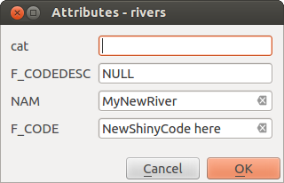
Fig. 12.84 Enter Attribute Values Dialog after digitizing a new vector feature
12.3.4.3. Vertex tool
QGIS provides two tools to interact with vector features vertices:
 Vertex Tool (Current Layer): only
overlaid features in the active layer (in the Layers
panel) are affected
Vertex Tool (Current Layer): only
overlaid features in the active layer (in the Layers
panel) are affected Vertex Tool (All Layers): any overlaid features
in all editable layers are affected. This allows you to edit features
without switching the active layer or edit multiple layers at once
(e.g., country and their regions boundaries)
Vertex Tool (All Layers): any overlaid features
in all editable layers are affected. This allows you to edit features
without switching the active layer or edit multiple layers at once
(e.g., country and their regions boundaries)
For any editable vector layer, the vertex tools provide manipulation capabilities of feature vertices similar to CAD programs. It is possible to select multiple vertices at once and to move, add or delete them altogether. The vertex tools also support the topological editing feature. They are selection persistent, so when some operation is done, selection stays active for this feature and tool.
Tip
Drawing a series of new vertices
The vertex tool does not support automatic tracing and is optimized for
editing individual vertices and moving or deleting an arbitrary selection
of multiple vertices. Try using the  Reshape Features
tool when you need to replace or insert a series of new vertices,
especially if you want to trace other features.
Reshape Features
tool when you need to replace or insert a series of new vertices,
especially if you want to trace other features.
It is important to set the property  Search Radius:
 to a number greater than zero. Otherwise, QGIS will
not be able to tell which vertex is being edited and will display a warning.
to a number greater than zero. Otherwise, QGIS will
not be able to tell which vertex is being edited and will display a warning.
Tip
Vertex Markers
QGIS supports different kinds of vertex markers:
‘Semi-transparent circle’, ‘Cross’ and ‘None’. To change the marker style,
choose from the
menu, click on the Digitizing
tab and select the appropriate entry.
Basic operations
Given a layer in edit mode, start by activating the vertex tool. Red circles will appear when hovering vertices.
Selecting vertices: You can select vertices by:
Clicking on them one at a time holding Shift key pressed
Click-and-dragging a rectangle surrounding the target vertices
Drawing a polygon surrounding the target vertices: Hold Alt and click using the vertex tool to start digitizing a polygon. Each subsequent click adds a new vertex to the rubberband polygon. Backspace or Delete removes last added rubberband vertex. Esc cancels the polygon selection mode, as also does backspacing/deleting all of the rubberband’s vertices. Right click finalizes the polygon digitizing and selects all vertices within the rubberband polygon.
When a vertex is selected, its color changes to blue. To add more vertices to the current selection, hold down the Shift key while proceeding as above. To remove vertices from the selection, hold down Ctrl.
Tip
Feature selection bounds vertex tool
Vertices can be selected across different features (or layers). If you are looking for vertices of a specific feature in a crowded place, first select that feature. Then draw the rectangle or polygon selector with the vertex tool around the vertices: only the selected feature’s vertices are selected.
This is also the case if you display the feature in the vertex editor panel.
Batch vertex selection mode: The batch selection mode can be activated by pressing Shift+R. Select a first node with one single click, and then hover without clicking another vertex. This will dynamically select all the nodes in between using the shortest path (for polygons).
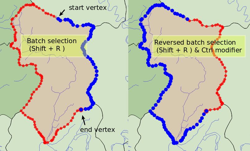
Fig. 12.85 Batch vertex selection using Shift+R
Press Ctrl will invert the selection, selecting the longest path along the feature boundary. Ending your node selection with a second click, or pressing Esc will escape the batch mode.
Adding vertices: To add a vertex to a line or polygon geometry, hold Shift and double-click the place on the segment.
When hovering a segment, a virtual new node appears on the center. Click on it, move the cursor to a new location and click again to add a new vertex. For lines, a virtual node is also proposed at both extremities: click on it, do subsequent clicks and finish with a right-click; this allows to easily extend an existing line.
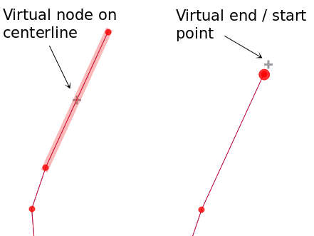
Fig. 12.86 Virtual nodes for adding vertices
Deleting vertices: Select the vertices and click the Delete key. Deleting all the vertices of a feature generates, if compatible with the datasource, a geometryless feature. Note that this doesn’t delete the complete feature, just the geometry part. To delete a complete feature use the
 Delete Selected tool.
Moving vertices: Select all the vertices you want to move, click on a selected vertex or edge, and click on the desired new location. You can use the snapping to feature capabilities and the Advanced Digitizing Panel constraints for distance, angles, exact X and Y location before the second click. All the selected vertices will be translated.
However, if the snap-to-grid option is enabled, selected vertices are snapped to the closest grid intersection to their translated position. Unselected vertices are also moved to their closest grid intersection. There is no simple translation.
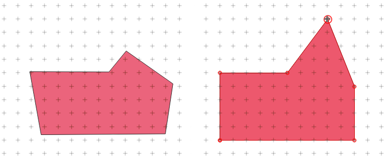
Fig. 12.87 Moving the top vertex snaps all the vertices to the grid
Converting adjacent segments to/from curve: Select the center vertex of the segment you want to convert, hit the O letter key. If the vertex was in a curve, the curve is converted into straight lines. If the vertex was between two straight lines, they are converted into a curve. A first or a last vertex of a line can’t be converted to a center vertex curve. The layer must be compatible with curve geometry type.
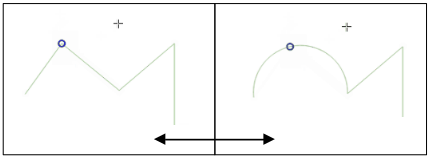
Fig. 12.88 Switch from curve to straight lines with O letter
Each change made with the vertex tool is stored as a separate entry in the Undo dialog. Remember that all operations support topological editing when this is turned on. On-the-fly projection is also supported.
The Vertex Editor Panel
With enabling a vertex tool, you also open the Vertex Editor panel. Right-clicking over a feature fills the panel with the list of all the vertices of the feature with their x, y (z, m if applicable) coordinates and r (for the radius, in case of circular geometry). The feature is also made exclusive for editing, meaning that the edit of any other features is disabled:
Selecting a row in the table does select the corresponding vertex in the map canvas, and vice versa.
Clicking or dragging over the map canvas will only select or move vertices and segments of that feature
Change a coordinate in the table and the vertex position is updated. This is a convenient way to edit Z coordinate or M value on vertices.
You can also select multiple rows and delete them altogether.
New vertices can only be added to the bound feature
If you do not want the Vertex Editor panel to immediately show
each time you interact with vertex tools (and potentially hide other panels
or disturb panels placement), uncheck the Auto-open table entry
in the  Options menu at the top of the panel.
You can then also close the panel.
To reopen the panel, you would need to right-click over a panel or toolbar and
select it in the list or tick the Show vertex editor entry in
the Digitizing toolbar.
Options menu at the top of the panel.
You can then also close the panel.
To reopen the panel, you would need to right-click over a panel or toolbar and
select it in the list or tick the Show vertex editor entry in
the Digitizing toolbar.
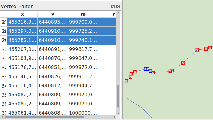
Fig. 12.89 Vertex editor panel showing selected nodes
12.3.4.4. Rules of Z coordinate or M value assignment
Digitizing 3D vector features or features with M value is not that different from (X,Y) 2D layers’. Tools and options described in this chapter are still available and help you place the vertex or point in a planar environment. Then you may need to handle the Z coordinate (or M value) assignment:
By default, QGIS will assign to new vertices the Default Z value (respectively Default M value) set in the tab. If the Advanced Digitizing Panel is in use, then the value is taken from its z (respectively m) widget.
When snapping to a vertex, the new or moved vertex takes the snapped one’s Z or M value.
When snapping to a segment while the topological editing is on, then the new vertex Z or M value is interpolated along the segment.
If the z (respectively m) widget of the Advanced Digitizing Panel is
 locked, then its value is
applied to the vertex, taking precedence over any snapped vertex or segment
Z or M value.
locked, then its value is
applied to the vertex, taking precedence over any snapped vertex or segment
Z or M value.
To edit Z or M values of an existing feature, you can use the Vertex editor panel. To create features with custom Z or M values you may want to rely on the Advanced Digitizing Panel.
12.3.4.5. Cutting, Copying and Pasting Features
Selected features can be cut, copied and pasted between layers in the same
QGIS project, as long as destination layers are set to
Toggle editing beforehand.
Tip
Transform polygon into line and vice-versa using copy/paste
Copy a line feature and paste it in a polygon layer: QGIS pastes in the target layer a polygon whose boundary corresponds to the closed geometry of the line feature. This is a quick way to generate different geometries of the same data.
Features can also be pasted to external applications as text. That is, the features are represented in CSV format, with the geometry data appearing in the OGC Well-Known Text (WKT) format. WKT and GeoJSON features from outside QGIS can also be pasted to a layer within QGIS.
When would the copy and paste function come in handy? Well, it turns
out that you can edit more than one layer at a time
and copy/paste features between layers. Why would we want to do this?
Say we need to do some work on a new layer but only need one or two
lakes, not the 5,000 on our big_lakes layer.
We can create a new layer and use copy/paste to plop the needed lakes
into it.
As an example, we will copy some lakes to a new layer:
Load the layer you want to copy from (source layer)
Load or create the layer you want to copy to (target layer)
Start editing for target layer
Make the source layer active by clicking on it in the legend
Use the
 Select Features by area or single click
tool to select the feature(s) on the source layer
Select Features by area or single click
tool to select the feature(s) on the source layerClick on the
 Copy Features tool
Make the destination layer active by clicking on it in the legend
Click on the
 Paste Features tool
Stop editing and save the changes
What happens if the source and target layers have different schemas (field names and types are not the same)? QGIS populates what matches and ignores the rest. If you don’t care about the attributes being copied to the target layer, it doesn’t matter how you design the fields and data types. If you want to make sure everything - the feature and its attributes - gets copied, make sure the schemas match.
When you paste features into another layer,
QGIS checks the attribute values against the constraints defined
in the destination layer (for example, NOT NULL, Unique, or expression constraints).
If one or more pasted features contain invalid attribute values that
do not meet these constraints, a dialog will
appear, listing all affected features and fields.
When pasting a single feature, you can decide whether to:
Edit the invalid values directly in the dialog. The corrected values will be used when pasting.
Paste Anyway: the feature is pasted as-is, even with invalid values.

Fig. 12.90 Dialog for handling invalid attribute values when pasting a single feature
When pasting multiple features, the dialog lists all invalid fields across all features, allowing bulk review and correction. You can decide per field or per feature whether to:
Edit the invalid values directly in the dialog. The corrected values will be used when pasting.
Discard All: no features pasted.
Discard All Invalid: pasted only features with valid attribute values.
Paste All (Including Invalid): all features are pasted as-is, even with invalid values.
Skip: skip the specific feature, allowing proceeding with the rest.

Fig. 12.91 Dialog for handling invalid attribute values when pasting multiple features
Note
Congruency of Pasted Features
If your source and destination layers use the same projection, then the pasted features will have geometry identical to the source layer. However, if the destination layer is a different projection, then QGIS cannot guarantee the geometry is identical. This is simply because there are small rounding-off errors involved when converting between projections.
Tip
Copy string attribute into another
If you have created a new column in your attribute table with type ‘string’ and want to paste values from another attribute column that has a greater length the length of the column size will be extended to the same amount. This is because the GDAL Shapefile driver knows to auto-extend string and integer fields to dynamically accommodate for the length of the data to be inserted.
12.3.4.6. Deleting Selected Features
If we want to delete an entire feature (attribute and geometry), we can do that
by first selecting the geometry using the regular Select
Features by area or single click tool. Selection can also be done from the attribute
table. Once you have the selection set, press Delete or Backspace
key or use the Delete Selected tool to delete
the features. Multiple selected features can be deleted at once.
The  Cut Features tool on the digitizing toolbar can
also be used to delete features. This effectively deletes the feature but
also places it on a “spatial clipboard”. So, we cut the feature to delete.
We could then use the Paste Features tool to put it back,
giving us a one-level undo capability. Cut, copy, and paste work on the
currently selected features, meaning we can operate on more than one at a time.
Cut Features tool on the digitizing toolbar can
also be used to delete features. This effectively deletes the feature but
also places it on a “spatial clipboard”. So, we cut the feature to delete.
We could then use the Paste Features tool to put it back,
giving us a one-level undo capability. Cut, copy, and paste work on the
currently selected features, meaning we can operate on more than one at a time.
12.3.4.7. Undo and Redo
The  Undo and
  Redo tools allows you to undo or redo
vector editing operations. There is also a dockable widget, which shows all
operations in the undo/redo history (see Fig. 12.92). This widget is not
displayed by default; it can be displayed by right-clicking on the toolbar and
activating the Undo/Redo Panel checkbox. The Undo/Redo capability
is however active, even if the widget is not displayed.
Redo tools allows you to undo or redo
vector editing operations. There is also a dockable widget, which shows all
operations in the undo/redo history (see Fig. 12.92). This widget is not
displayed by default; it can be displayed by right-clicking on the toolbar and
activating the Undo/Redo Panel checkbox. The Undo/Redo capability
is however active, even if the widget is not displayed.
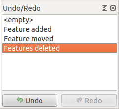
Fig. 12.92 Redo and Undo digitizing steps
When Undo is hit or Ctrl+Z (or Cmd+Z) pressed, the state of all features and attributes are reverted to the state before the reverted operation happened. Changes other than normal vector editing operations (for example, changes done by a plugin) may or may not be reverted, depending on how the changes were performed.
To use the undo/redo history widget, simply click to select an operation in the history list. All features will be reverted to the state they were in after the selected operation.
12.3.4.8. Saving Edited Layers
When a layer is in editing mode, any changes remain in the memory of QGIS.
Therefore, they are not committed/saved immediately to the data source or disk.
If you want to save edits to the current layer but want to continue editing
without leaving the editing mode, you can click the
Save Layer Edits button. When you turn editing mode off with
Toggle editing (or quit QGIS for that matter),
you are also asked if you want to save your changes or discard them.
If the changes cannot be saved (e.g., disk full, or the attributes have values that are out of range), the QGIS in-memory state is preserved. This allows you to adjust your edits and try again.
Tip
Data Integrity
It is always a good idea to back up your data source before you start editing. While the authors of QGIS have made every effort to preserve the integrity of your data, we offer no warranty in this regard.
Saving multiple layers at once
This feature allows the digitization of multiple layers. Choose
 Save for Selected Layers to save all changes you
made in multiple layers. You also have the opportunity to
Save for Selected Layers to save all changes you
made in multiple layers. You also have the opportunity to
 Rollback for Selected Layers, so that the
digitization may be withdrawn for all selected layers.
If you want to stop editing the selected layers,
Rollback for Selected Layers, so that the
digitization may be withdrawn for all selected layers.
If you want to stop editing the selected layers,  Cancel
for Selected Layer(s) is an easy way.
Cancel
for Selected Layer(s) is an easy way.
The same functions are available for editing all layers of the project.
Tip
Use transaction group to edit, save or rollback multiple layers changes at once
When working with layers from the same PostGreSQL database, activate the Automatically create transaction groups where possible option in to sync their behavior (enter or exit the edit mode, save or rollback changes at the same time).
12.3.5. Advanced digitizing
Icon |
Purpose |
Icon |
Purpose |
|---|---|---|---|
|
Enable Advanced Digitizing Tools |
||
|
Move Feature(s) |
|
Copy and Move Feature(s) |
|
Rotate Feature(s) |
|
Simplify Feature |
|
Scale Feature |
||
|
Add Ring |
|
Add Part |
|
Fill Ring |
|
Swap direction |
|
Delete Ring |
|
Delete Part |
|
Offset Curve |
|
Reshape Features |
|
Split Parts |
|
Split Features |
|
Merge Attributes of Selected Features |
|
Merge Selected Features |
|
Rotate Point Symbols |
|
Offset Point Symbols |
|
Trim or Extend Feature |


12.3.5.1. Move Feature(s)
The  Move Feature(s) tool allows you to move existing features:
Select the feature(s) to move.
Click on the map canvas to indicate the origin point of the displacement; you can rely on snapping capabilities to select an accurate point.
You can also take advantages of the advanced digitizing constraints to accurately set the origin point coordinates. In that case:
First click on the
 button to enable the panel.
Type
xand enter the corresponding value for the origin point you’d like to use. Then press the button next to the option to lock the value.Do the same for the
ycoordinate.Click on the map canvas and your origin point is placed at the indicated coordinates.
Move over the map canvas to indicate the destination point of the displacement, still using snapping mode or, as above, use the advanced digitizing panel which would provide complementary
distanceandangleplacement constraints to place the end point of the translation.Click on the map canvas: the whole features are moved to new location.
Likewise, you can create a translated copy of the feature(s) using the
 Copy and Move Feature(s) tool.
Note
If no feature is selected when you first click on the map canvas with any of the Move Feature(s) or Copy and Move Feature(s) tools, then only the feature under the mouse is affected by the action. So, if you want to move several features, they should be selected first.
12.3.5.2. Rotate Feature(s)
Use the  Rotate Feature(s) tool to rotate one or multiple
features in the map canvas:
Rotate Feature(s) tool to rotate one or multiple
features in the map canvas:
Press the
Rotate Feature(s) iconThen click on the feature to rotate. The feature’s centroid is referenced as rotation center, a preview of the rotated feature is displayed and a widget opens showing the current Rotation angle.
Click on the map canvas when you are satisfied with the new placement or manually enter the rotation angle in the text box. You can also use the Snap to ° box to constrain the rotation values.
If you want to rotate several features at once, they shall be selected first, and the rotation is by default around the centroid of their combined geometries.
You can also use an anchor point different from the default feature centroid: press the Ctrl button, click on the map canvas and that point will be used as the new rotation center.
If you hold Shift before clicking on the map, the rotation will be done in 45 degree steps, which can be modified afterwards in the user input widget.
To abort feature rotation, press the ESC button or click on the
Rotate Feature(s) icon.
12.3.5.3. Scale Feature
The  Scale Feature tool is similar to the Rotate feature. Though instead of performing
a rotation of selected features, it rescales their geometry. The change is
performed in relation to the anchor point and the scale ratio can be manually specified
in the widget that appears in the upper corner of the canvas.
Scale Feature tool is similar to the Rotate feature. Though instead of performing
a rotation of selected features, it rescales their geometry. The change is
performed in relation to the anchor point and the scale ratio can be manually specified
in the widget that appears in the upper corner of the canvas.
12.3.5.4. Simplify Feature
The  Simplify Feature tool allows you to interactively
reshape a line or polygon geometry by reducing or densifying the number of
vertices, as long as the geometry remains valid:
Simplify Feature tool allows you to interactively
reshape a line or polygon geometry by reducing or densifying the number of
vertices, as long as the geometry remains valid:
Select the
Simplify Feature tool.Click on the feature or drag a rectangle over the features.
A dialog pops up allowing you to define the Method to apply, ie whether you would like to:
simplify the geometry, meaning less vertices than the original. Available methods are
Simplify by distance,Simplify by snapping to gridorsimplify by area (Visvalingam). You’d then need to indicate the value of Tolerance inLayer units,Pixelsormap unitsto use for simplification. The higher the tolerance is the more vertices can be deleted.or densify the geometries with new vertices thanks to the
Smoothoption: for each existing vertex, two vertices are placed on each of the segments originated from it, at an Offset distance representing the percentage of the segment length. You can also set the number of Iterations the placement would be processed: the more iterations, the more vertices and smoother is the feature.
Settings that you used will be saved when leaving a project or an edit session. So you can go back to the same parameters the next time you simplify a feature.
A summary of the modifications that would apply is shown at the bottom of the dialog, listing number of features and number of vertices (before and after the operation and the ratio the change represents). Also, in the map canvas, the expected geometry is displayed over the existing one, using the rubberband color.
When the expected geometry fits your needs, click OK to apply the modification. Otherwise, to abort the operation, you can either press Cancel or right-click in the map canvas.
Note
Unlike the feature simplification option in menu which simplifies the geometry just for rendering,
the Simplify Feature tool permanently modifies
feature’s geometry in data source.
12.3.5.5. Add Part
You can  Add Part to a selected feature generating a
multipoint, multiline or multipolygon feature. The new part must be digitized
outside the existing one which should be selected beforehand.
Add Part to a selected feature generating a
multipoint, multiline or multipolygon feature. The new part must be digitized
outside the existing one which should be selected beforehand.
The Add Part can also be used to add a geometry to a geometryless
feature. First, select the feature in the attribute table and digitize the new
geometry with the Add Part tool.
Note
Order of vertices in polygon parts
Unlike the OGC standards, QGIS doesn’t constrain vertices of the exterior boundary of a polygon feature to be ordered counterclockwise. Thus, you can find both directions in a layer. However, every parts of the same multipolygon feature will have their outer vertices ordered following the same direction.
You can however use the Force right-hand-rule algorithm to constrain features of a layer to have vertices of their outer boundaries ordered in the clockwise direction.
12.3.5.6. Delete Part
The  Delete Part tool allows you to delete parts from
multifeatures (e.g., to delete polygons from a multi-polygon feature). This
tool works with all multi-part geometries: point, line and polygon. Furthermore,
it can be used to totally remove the geometric component of a feature.
To delete a part, simply click within the target part.
Delete Part tool allows you to delete parts from
multifeatures (e.g., to delete polygons from a multi-polygon feature). This
tool works with all multi-part geometries: point, line and polygon. Furthermore,
it can be used to totally remove the geometric component of a feature.
To delete a part, simply click within the target part.
12.3.5.7. Add Ring
You can create ring polygons using the  Add Ring icon in the toolbar.
This means that inside an existing area, it is possible to digitize further polygons
that will occur as a ‘hole’, so only the area between the boundaries
of the outer and inner polygons remains as a ring polygon.
Add Ring icon in the toolbar.
This means that inside an existing area, it is possible to digitize further polygons
that will occur as a ‘hole’, so only the area between the boundaries
of the outer and inner polygons remains as a ring polygon.
To add a ring:
Select the feature(s) to modify
Activate the
Add Ring toolDraw a polygon within the selected geometries, using the aforementioned techniques. A hole appears in the selected geometries.
If no geometry is selected when the ring is drawn, then a hole is added to each of the polygons the ring is drawn over.
Note
Order of vertices in polygon rings
Unlike the OGC standards, QGIS doesn’t constrain vertices of the exterior boundary of a polygon feature to be ordered counterclockwise. Thus, you can find both directions in a layer. However, every rings of the same (multi)polygon feature will have their vertices ordered in the opposite direction to the outer boundary’s.
You can however use the Force right-hand-rule algorithm to constrain features of a layer to have vertices of their outer boundaries ordered in the clockwise direction, and vertices of their interior rings ordered in the counter-clockwise direction.
12.3.5.8. Fill Ring
The  Fill Ring tool helps you create polygon feature that
totally falls within another one without any overlapping area; that is the new
feature covers a hole within the existing one. To create such a feature:
Fill Ring tool helps you create polygon feature that
totally falls within another one without any overlapping area; that is the new
feature covers a hole within the existing one. To create such a feature:
Select the
Fill Ring tool.Draw a new polygon over the existing feature: QGIS adds a ring to its geometry (like if you used the
Add Ring tool) and creates a new
feature whose geometry matches the ring (like if you traced
over the interior boundaries with the Add polygon
feature tool).Or alternatively, if the ring already exists on the feature, place the mouse over the ring and left-click while pressing Shift: a new feature filling the hole is drawn at that place.
The Feature Attributes form of the new feature opens, pre-filled with values of the “parent” feature and/or fields constraints.
12.3.5.9. Delete Ring
The  Delete Ring tool allows you to delete rings within
an existing polygon, by clicking inside the hole. This tool only works with
polygon and multi-polygon features. It doesn’t
change anything when it is used on the outer ring of the polygon.
Delete Ring tool allows you to delete rings within
an existing polygon, by clicking inside the hole. This tool only works with
polygon and multi-polygon features. It doesn’t
change anything when it is used on the outer ring of the polygon.
12.3.5.10. Reshape Features
You can reshape line and polygon features using the
Reshape Features tool on the toolbar. For lines, it replaces the line
part from the first to the last intersection with the original line.
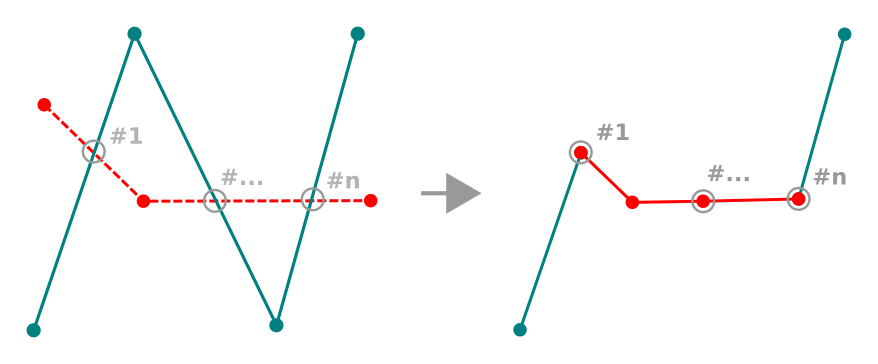
Fig. 12.93 Reshape line
Tip
Extend linestring geometries with reshape tool
Use the Reshape Features tool to extend existing linestring
geometries: snap to the first or last vertex of the line and draw a new one.
Validate and the feature’s geometry becomes the combination of the two lines.
For polygons, it will reshape the polygon’s boundary. For it to work, the reshape tool’s line must cross the polygon’s boundary at least twice. To draw the line, click on the map canvas to add vertices. To finish it, just right-click. Like with the lines, only the segment between the first and the last intersections is considered. The reshape line’s segments that are inside the polygon will result in cropping it, where the ones outside the polygon will extend it.
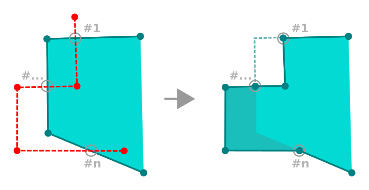
Fig. 12.94 Reshape polygon
With polygons, reshaping can sometimes lead to unintended results. It is mainly useful to replace smaller parts of a polygon, not for major overhauls, and the reshape line is not allowed to cross several polygon rings, as this would generate an invalid polygon.
Note
The reshape tool may alter the starting position of a polygon ring or a closed line. So, the point that is represented ‘twice’ will not be the same any more. This may not be a problem for most applications, but it is something to consider.
12.3.5.11. Offset Curves
The  Offset Curve tool creates parallel shifts of
line layers.
The tool can be applied to the edited layer (the geometries are modified)
or also to background layers (in which case it creates copies of the lines /
rings and adds them to the edited layer).
It is thus ideally suited for the creation of distance line layers.
The User Input dialog pops-up, showing the displacement distance
and other settings.
Offset Curve tool creates parallel shifts of
line layers.
The tool can be applied to the edited layer (the geometries are modified)
or also to background layers (in which case it creates copies of the lines /
rings and adds them to the edited layer).
It is thus ideally suited for the creation of distance line layers.
The User Input dialog pops-up, showing the displacement distance
and other settings.
To create a shift of a line or polygon layer, you must first go into editing mode
and activate the Offset Curve tool.
Then click on a feature to shift it.
Move the mouse and click where wanted or enter the desired distance in
the user input widget. Holding Ctrl during the 2nd click will make an offset copy.
Your changes may then be saved with the
Save Layer Edits tool.
For geometries on background layers make sure that snapping is on and hold Ctrl to select the geometry from the background. Also hold Ctrl when doing the second click. Geometries will be converted to the target layer geometry type.
QGIS options dialog (Digitizing tab then Curve offset tools section) or
the  icon in the User Input dialog allows
you to configure some parameters like Join style,
Quadrant segments, Miter limit and End cap style.
icon in the User Input dialog allows
you to configure some parameters like Join style,
Quadrant segments, Miter limit and End cap style.
12.3.5.12. Reverse Line
Changing the direction of a line geometry can be useful for cartographical purposes (e.g., for orienting symbols or labels that follow the line direction) or when preparing for network analysis where the direction of flow or travel matters.
This tool works only on line layers. For multipart lines, you can reverse individual parts without affecting the other parts of the feature.
To change a line direction:
Select a line layer in the Layers panel and make it editable.
Activate the reverse line tool by clicking
 Reverse line in the Advanced Digitizing toolbar.
Move the pointer over a line feature. The part under the cursor is highlighted.
Click on the line: the direction of the line (or part) is reversed.
You can reverse other lines by clicking on them.
Tip
For bulk line direction changes, use the Reverse line direction processing algorithm which can reverse all lines in a layer or a selection at once.
12.3.5.13. Split Features
Use the  Split Features tool to split a feature into two
or more new and independent features, ie. each geometry corresponding to a new
row in the attribute table.
Split Features tool to split a feature into two
or more new and independent features, ie. each geometry corresponding to a new
row in the attribute table.
To split line or polygon features:
Select the
Split Features tool.Draw a line across the feature(s) you want to split. If a selection is active, only selected features are split. The original feature is then assigned the biggest geometry resulting from the splitting, and new features are created for the remaining parts. Fields of the features are filled/updated according to the datasource provider rules or their splitting policy.
You can then as usual modify any of the attributes of any resulting feature.
Tip
Split a polyline into new features in one-click
Using the Split Features tool, snap and click on an
existing vertex of a polyline feature to split that feature into two new features.
12.3.5.14. Split parts
In QGIS it is possible to split the parts of a multi part feature so that the
number of parts is increased. Just draw a line across the part you want to split using
the  Split Parts icon.
Tip
Split a polyline into new parts in one-click
Using the Split Parts tool, snap and click on an
existing vertex of a polyline feature to split the feature into two new
polylines belonging to the same feature.
12.3.5.15. Merge selected features
The  Merge Selected Features tool allows you to create
a new feature by merging existing ones: their geometries are merged to generate
a new one. If features don’t have common boundaries,
a multipolygon/multipolyline/multipoint feature is created.
Merge Selected Features tool allows you to create
a new feature by merging existing ones: their geometries are merged to generate
a new one. If features don’t have common boundaries,
a multipolygon/multipolyline/multipoint feature is created.
First, select the features you’d like to combine.
Then press the
Merge Selected Features button.In the new dialog, the Merge line at the bottom of the table shows the attributes of the resulting feature. If any Merge policy have been defined, they are automatically applied to populate this row. However, you can override these values manually. Modify the values in the following ways:
manually replacing the value in the corresponding cell;
selecting a row in the table and pressing Take attributes from selected feature to use the values of this initial feature;
pressing the Take attributes from the largest geometry to use the attributes from the longest line feature, the largest polygon, or the multipoints with the most parts;
pressing Skip all fields to use empty attributes;
expanding the drop down menu at the top of the table, select any of the above options to apply to the corresponding field only. There, you can also choose to aggregate the initial features attributes (Minimum, Maximum, Median, Sum, Count, Concatenation… depending on the type of the field. see Statistical Summary Panel for the full list of functions).
Note
If the layer has default values or clauses present on fields, these are used as the initial value for the merged feature.
Press OK to apply the modifications. A single (multi)feature is created in the layer, replacing the previously selected ones.
12.3.5.16. Merge attributes of selected features
The  Merge Attributes of Selected Features tool
allows you to apply same attributes to features without merging their boundaries.
The dialog is the same as the
Merge Attributes of Selected Features tool
allows you to apply same attributes to features without merging their boundaries.
The dialog is the same as the Merge Selected Features tool’s except that
unlike that tool, selected objects are kept with their geometry while some of their
attributes are made identical.
12.3.5.17. Rotate Point Symbols
The  Rotate Point Symbols allows you to individually
change the rotation of point symbols in the map canvas.
Rotate Point Symbols allows you to individually
change the rotation of point symbols in the map canvas.
First, you need to indicate the field to store the rotation value in. This is made by assigning a field to the symbol data-defined rotation property:
In the dialog, browse to the symbol editor dialog.
Click the
 Data-defined override widget near the
Rotation option of the top Marker level (preferably)
of the symbol layers.
Data-defined override widget near the
Rotation option of the top Marker level (preferably)
of the symbol layers.Choose a field in the Field Type combobox. Values of this field are hence used to rotate each feature’s symbol accordingly.
You can also check the Store data in project entry to generate an auxiliary data storage field to control the rotation value.
Note
Make sure that the same field is assigned to all the symbol layers
Setting the data-defined rotation field at the topmost level of the symbol tree automatically propagates it to all the symbol layers, a prerequisite to perform graphical symbol rotation with the Rotate Point Symbols tool. Indeed, if a symbol layer does not have the same field attached to its rotation property, the tool will not work.
Fig. 12.95 Rotating a point symbol
Then click on a point symbol in the map canvas with the
Rotate Point Symbols toolMove the mouse around. A red arrow with the rotation value will be visualized (see Fig. 12.95). If you hold the Ctrl key while moving, the rotation will be done in 15 degree steps.
When you get the expected angle value, click again. The symbol is rendered with this new rotation and the associated field is updated accordingly.
You can right-click to abort symbol rotation.
12.3.5.18. Offset Point Symbols
The  Offset Point Symbols allows you to interactively
change the rendered position of point symbols in the map canvas. This tool behaves
like the Rotate Point Symbols tool except that it
requires you to connect a field to the data-defined Offset (X,Y)
property of each layer of the symbol. The field will then be populated with the
offset coordinates for the features whose symbol is moved in the map canvas.
Offset Point Symbols allows you to interactively
change the rendered position of point symbols in the map canvas. This tool behaves
like the Rotate Point Symbols tool except that it
requires you to connect a field to the data-defined Offset (X,Y)
property of each layer of the symbol. The field will then be populated with the
offset coordinates for the features whose symbol is moved in the map canvas.
Associate a field to the data-defined widget of the Offset (X,Y) property of the symbol. If the symbol is made with many layers, you may want to assign the field to each of them
Select the
Offset Point Symbols toolClick a point symbol
Move to a new location
Click again. The symbol is moved to the new place. Offset values from the original position are stored in the linked field.
You can right-click to abort symbol offset.
Note
The Offset Point Symbols tool doesn’t
move the point feature itself; you should use the
Vertex Tool (Current Layer) or  Move Feature
tool for this purpose.
Move Feature
tool for this purpose.
12.3.5.19. Trim/Extend Feature
The  Trim/Extend tool allows you to shorten or lengthen
segments of a (multi)line or (multi)polygon geometry to converge with a
selected segment (the cutting line). This results in a modified geometry
with a vertex snapped to a reference segment or in its prolongation.
Depending on how the selected geometries are placed in relation to each
other, the tool will either:
Trim/Extend tool allows you to shorten or lengthen
segments of a (multi)line or (multi)polygon geometry to converge with a
selected segment (the cutting line). This results in a modified geometry
with a vertex snapped to a reference segment or in its prolongation.
Depending on how the selected geometries are placed in relation to each
other, the tool will either:
Trim: removes parts of the line segment or polygon boundary, beyond the cutting line
Extend: extends polygon boundaries or line segments so that they can snap to the cutting line.
In order to trim or extend existing geometries:
Select the
Trim/Extend toolClick the reference segment, i.e., the segment with respect to which you want to extend or trim another segment. It doesn’t need to be on the active layer. A red dotted line appears, visually extending the reference segment across the map canvas according to the active layer’s CRS.
Hover over the target segment, i.e., the one you want to trim or extend. It does not need to be the last segment of the geometry, but has to be on the active layer. QGIS displays a preview of the feature’s geometry with the segment limited to its intersection with the highlighted red dotted extending line.
If an extension of the segment is required, click anywhere on the segment.
In the case of a trim, click the part that should remain.
In either case, the feature’s geometry is updated accordingly. When both segments are in 3D, the tool performs an interpolation on the limit segment to get the Z value.
If you need to use the same reference segment for trimming or extending many features:
Press Shift while selecting the reference segment.
Click consecutively on the segments to modify and each will be trimmed or extended accordingly.

Fig. 12.96 Trimming and extending multiple lines from different layers in different CRS
Note
Snapping is automatically enabled when this tool is activated. Your original snapping settings will be restored once the tool is deactivated.
Attention
Pay attention to the modified geometry while using the
Trim/Extend tool. Depending on the inputs, it can create invalid
geometries, potentially resulting in failure at layer saving.
12.3.6. Shape digitizing
The Shape Digitizing toolbar offers a set of tools to draw lines
or polygons features of regular shape.
It is synchronized with the Digitize Shape
geometry drawing method you can select on the Digitizing Toolbar.
To use it:
Display the toolbar:
Select a tool that creates or modifies the shape of a geometry, e.g.
Add line feature, Add polygon feature,
Add part, Add ring, Reshape Features, …The
Digitize with segment button
on the Digitizing Toolbar is enabled.
The first time, you may need to switch it to the Digitize Shape
in order to enable tools on the Shape Digitizing toolbar.Pick a shape digitizing tool and draw.
12.3.6.1. Circular string by radius
The  Circular string by radius button allows
to add line or polygon features with a circular geometry, given two nodes
on the curve and a radius:
Circular string by radius button allows
to add line or polygon features with a circular geometry, given two nodes
on the curve and a radius:
Left click twice to place the two points on the geometry.
A Radius widget in the top right corner of the map canvas displays current radius (corresponding to distance between the points). Edit that field to the value you want.
An overview of the arcs matching these constraints is displayed while moving around the cursor. Right-click to validate when the expected arc is shown.
Add a new point to start shaping another arc.
Note
Curved geometries are stored as such only in compatible data provider
Although QGIS allows to digitize curved geometries within any editable data format, you need to be using a data provider (e.g. PostgreSQL, Oracle Spatial, memory layer, GML or WFS) that supports curves to have features stored as curved, otherwise QGIS segmentizes the circular arcs.
12.3.6.2. Draw Circles
There is a set of tools for drawing circles. The tools are described below.
Circles are converted into circular strings. Therefore, as explained in Circular string by radius, if allowed by the data provider, it will be saved as a curved geometry, if not, QGIS will segmentize the circular arcs.
 Circle from 2 points: The two points define the diameter
and the orientation of the circle. (Left-click, right-click)
Circle from 2 points: The two points define the diameter
and the orientation of the circle. (Left-click, right-click) Circle from 3 points: Draws a circle from three
known points on the circle. (Left-click, left-click, right-click)
Circle from 3 points: Draws a circle from three
known points on the circle. (Left-click, left-click, right-click) Circle by a center point and another point: Draws a circle
with a given center and a point on the circle (Left-click, right-click).
When used with the The Advanced Digitizing panel this tool can become a
“Add circle from center and radius” tool by setting and locking the distance
value after first click.
Circle by a center point and another point: Draws a circle
with a given center and a point on the circle (Left-click, right-click).
When used with the The Advanced Digitizing panel this tool can become a
“Add circle from center and radius” tool by setting and locking the distance
value after first click. Circle from 3 tangents: Draws a circle that is
tangential to three segments. Note that you must activate snapping to
segments (See Setting the snapping tolerance and search radius). Click on a segment to add a
tangent. If two tangents are parallel, the coordinates of the click on the
first parallel tangent are used to determine the positioning of the circle.
If three tangents are parallel, an error message appears and the input
is cleared. (Left-click, left-click, right-click)
Circle from 3 tangents: Draws a circle that is
tangential to three segments. Note that you must activate snapping to
segments (See Setting the snapping tolerance and search radius). Click on a segment to add a
tangent. If two tangents are parallel, the coordinates of the click on the
first parallel tangent are used to determine the positioning of the circle.
If three tangents are parallel, an error message appears and the input
is cleared. (Left-click, left-click, right-click) Circle from 2 tangents and a point: Similar
to circle from 3 tangents, except that you have to select two tangents, enter
a radius and select the desired center.
Circle from 2 tangents and a point: Similar
to circle from 3 tangents, except that you have to select two tangents, enter
a radius and select the desired center.
12.3.6.3. Draw Ellipses
There is a set of tools for drawing ellipses. The tools are described below.
Ellipses cannot be converted as circular strings, so they will always be segmented.
 Ellipse from center and two points: Draws an
ellipse with a given center, major axis and minor axis. (Left-click,
left-click, right-click)
Ellipse from center and two points: Draws an
ellipse with a given center, major axis and minor axis. (Left-click,
left-click, right-click) Ellipse from center and a point: Draws an
ellipse into a bounding box with the center and a corner. (Left-click,
right-click)
Ellipse from center and a point: Draws an
ellipse into a bounding box with the center and a corner. (Left-click,
right-click) Ellipse from extent: Draws an ellipse into a bounding
box with two opposite corners. (Left-click, right-click)
Ellipse from extent: Draws an ellipse into a bounding
box with two opposite corners. (Left-click, right-click) Ellipse from foci: Draws an ellipse by 2 points for
foci and a point on the ellipse. (Left-click, left-click, right-click)
Ellipse from foci: Draws an ellipse by 2 points for
foci and a point on the ellipse. (Left-click, left-click, right-click)
12.3.6.4. Draw Rectangles
There is a set of tools for drawing rectangles. The tools are described below.
 Rectangle from center and a point: Draws a
rectangle from the center and a corner. (Left-click, right-click)
Rectangle from center and a point: Draws a
rectangle from the center and a corner. (Left-click, right-click) Rectangle from extent: Draws a rectangle from two
opposite corners. (Left-click, right-click)
Rectangle from extent: Draws a rectangle from two
opposite corners. (Left-click, right-click) Rectangle from 3 points (distance): Draws an
oriented rectangle from three points. The first and second points determine the
length and angle of the first edge. The third point determines the length of the
other edge. One can use The Advanced Digitizing panel to set the length of the
edges. (Left-click, left-click, right-click)
Rectangle from 3 points (distance): Draws an
oriented rectangle from three points. The first and second points determine the
length and angle of the first edge. The third point determines the length of the
other edge. One can use The Advanced Digitizing panel to set the length of the
edges. (Left-click, left-click, right-click) Rectangle from 3 points (projected): Same as
the preceding tool, but the length of the second edge is computed from the
projection of the third point on the first edge. (Left-click, left-click,
right-click)
Rectangle from 3 points (projected): Same as
the preceding tool, but the length of the second edge is computed from the
projection of the third point on the first edge. (Left-click, left-click,
right-click)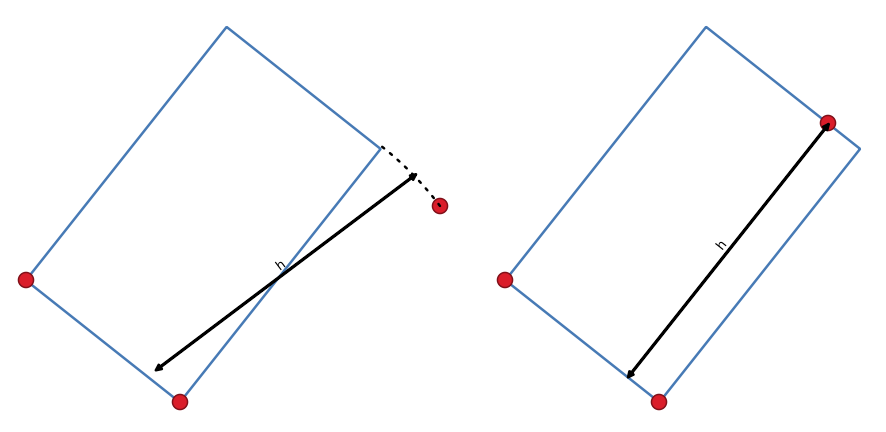
Fig. 12.97 Draw rectangle from 3 points using distance (right) and projected (left)
12.3.6.5. Draw Regular Polygons
There is a set of tools for drawing regular polygons. The tools are described below. Left-click to place the first point. A dialog appears, where you can set the number of polygon edges. Right-click to finish the regular polygon.
 Regular polygon from two points: Draws a regular
polygon where the two points determine the length and angle of the first edge.
Regular polygon from two points: Draws a regular
polygon where the two points determine the length and angle of the first edge. Regular polygon from center and a point:
Draws a regular polygon from the provided center point. The second point determines the
angle and distance to the middle of an edge.
Regular polygon from center and a point:
Draws a regular polygon from the provided center point. The second point determines the
angle and distance to the middle of an edge. Regular polygon from center and a corner:
Same as the preceding tool, but the second point determines the angle and
distante to a vertex.
Regular polygon from center and a corner:
Same as the preceding tool, but the second point determines the angle and
distante to a vertex.
12.3.7. The Advanced Digitizing panel
When capturing, reshaping, splitting new or existing geometries you also have the possibility to use the Advanced Digitizing panel. You can digitize lines exactly parallel or perpendicular to a particular angle or lock lines to specific angles. Furthermore, you can make a precise definition of your new geometry by entering X and Y coordinates as well as Z for 3D features, or M values.
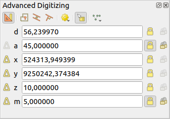
Fig. 12.98 The Advanced Digitizing panel
The Advanced Digitizing panel can be opened either with a right-click
on the toolbar, from menu or pressing
Ctrl+4. Once the panel is visible, click the Enable advanced
digitizing tools button to activate the set of tools.
Note
The tools are not enabled if the map view is in geographic coordinates.
The aim of the Advanced Digitizing tool is to lock coordinates, lengths, and angles when moving the mouse during the digitizing in the map canvas.
You can also create constraints with relative or absolute reference. Relative reference means that the next vertex constraints’ values will be relative to the previous vertex or segment.
12.3.7.1. The toolbar
At the top of the Digitizing panel, you find the following buttons:
- Enable advanced digitizing tools
 Construction mode: allows to capture the clicks’
positions to reuse as reference points to lock distance, angle, X, Y, Z or M
relative values. More details at Construction mode.
Construction mode: allows to capture the clicks’
positions to reuse as reference points to lock distance, angle, X, Y, Z or M
relative values. More details at Construction mode. Parallel to draw a line parallel to an existing one
(more at Parallel and perpendicular lines)
Parallel to draw a line parallel to an existing one
(more at Parallel and perpendicular lines) Perpendicular to draw a line perpendicular to an
existing one (more at Parallel and perpendicular lines)
Perpendicular to draw a line perpendicular to an
existing one (more at Parallel and perpendicular lines) Construction Tools provides a couple of options that
constrain the vertices placement based on extrapolated coordinates of
existing elements:
Construction Tools provides a couple of options that
constrain the vertices placement based on extrapolated coordinates of
existing elements:- Line Extension: hover over a segment and you get
a purple dotted line extending the segment across the map canvas.
You can snap the vertex anywhere on this virtual line.
- X/Y Point: hover over a vertex and you get
a purple dotted line along its X or Y coordinate, across the map canvas.
You can snap the vertex anywhere on this virtual line.
It is even possible to hover over two different vertices, generating virtual
coordinate lines for both, and snap to their intersection.
 2-circle Point Intersection: allows you to
digitize a point or vertex at the intersection of two circles.
(more at 2-circle point intersection).
2-circle Point Intersection: allows you to
digitize a point or vertex at the intersection of two circles.
(more at 2-circle point intersection).- Snap to common angles: when moving the cursor,
displays a virtual line that you can snap to to add the next vertex.
The snapping line is defined by the last added vertex
and an (absolute or relative to previous segment) angle from a preset list
(following steps of 0.1°, 0.5°, 1°, 5°, 10°, 15°, 18°, 22.5°, 30°, 45° or 90°).
Choose Do not snap to common angles to disable this feature.
Snapping to features can be used along with snapping to common angles for accurate digitizing. For a fine-grained control on how the target element to snap to is retained, you can indicate whether to prioritize snapping to features over common angles, and vice-versa under the Snapping priority entry. You can switch from one method to the other during the digitizing operation, and this avoids disabling any of the snapping options in the meantime. Press N (or Shift+N) during a digitizing operation to cycle through the angles list.
 Floater settings: if the Show floater item is checked,
a contextual menu with digitizing information follows the cursor during digitizing.
The values can be accessed using the panel’s shortcuts,
edited and Locked after validation (pressing Enter).
The type of information to display can be selected in the bottom part of the menu:
Floater settings: if the Show floater item is checked,
a contextual menu with digitizing information follows the cursor during digitizing.
The values can be accessed using the panel’s shortcuts,
edited and Locked after validation (pressing Enter).
The type of information to display can be selected in the bottom part of the menu:Show distance
Show angle
Show XY coordinates
Show Z value
Show M value
Show bearing/azimuth
Show common snapping angle
Below the toolbar, you will find a number of text boxes whose value reflects by default the position or movement of the cursor in the map canvas. Editing these values helps you constrain the position of the items you edit:
d for the distance from a reference position, usually the last edited vertex
a for the angle (absolute or relative) from a reference position, usually the last edited segment
x for the X coordinate of the pointer
y for the Y coordinate of the pointer
z for the default Z value or the Z coordinate of the vertex or segment under the pointer
m for the default M value or the M value of the vertex or segment under the pointer
12.3.7.2. Keyboard shortcuts
To speed up the use of Advanced Digitizing Panel, there are a couple of keyboard shortcuts available:
Key |
Simple |
Ctrl+ or Alt+ |
Shift+ |
|---|---|---|---|
D |
Set distance |
Lock distance |
|
A |
Set angle |
Lock angle |
Toggle relative angle to last segment |
X |
Set X coordinate |
Lock X coordinate |
Toggle relative X to last vertex |
Y |
Set Y coordinate |
Lock Y coordinate |
Toggle relative Y to last vertex |
Z |
Set Z coordinate |
Lock Z coordinate |
Toggle relative Z to last vertex |
M |
Set M value |
Lock M value |
Toggle relative M to last vertex |
C |
Toggle construction mode |
||
P |
Toggle perpendicular and parallel modes |
||
Note
Z coordinate and M value options are available only if compatible with the layer geometry dimension.
12.3.7.3. Absolute reference digitizing
When drawing a new geometry from scratch, it is very useful to have the possibility to start digitizing vertices at given coordinates.
For example, to add a new feature to a polygonal layer, click the
button. You can enter the exact coordinates where you want
to start editing the feature, i.e.:
Click the x text box (or use the X keyboard shortcut).
Type the X coordinate value you want and press Enter or click the
button to their right to lock the mouse to the X axis on the map
canvas.Click the y text box (or use the Y keyboard shortcut).
Type the Y coordinate value you want and press Enter or click the
button to their right to lock the mouse to the Y axis on the map
canvas.If the layer has Z coordinate or M values, the corresponding z or m widget is enabled and displays its default value, as set in tab.
Click the z or m text box (or use respectively the Z or M keyboard shortcut).
Type the coordinate value you want and press Enter or click the
button to their right to lock the value in the widget.
Note
Read Rules of Z coordinate or M value assignment for details on how Z coordinate and M values are automatically determined from existing features.
Two blue dotted lines and a green cross identify the exact coordinates you entered. Click on the map canvas to add a vertex at the green cross position.
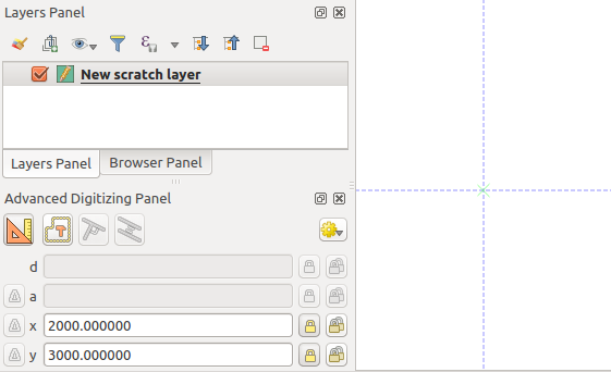
Fig. 12.99 Start drawing at given coordinates
You can proceed as above, adding a new set of coordinates for the next vertex, or switch to another mode of digitizing (e.g. segment, curve or stream).
If you want to draw a segment of a given length:
Click the d (distance) text box (keyboard shortcut D)
Type the distance value (in map units)
Press Enter or click the
button on the right to
lock the mouse in the map canvas to the length of the segment.
In the map canvas, the latest vertex is surrounded by a circle whose
radius is the value entered in the distance text box.
A cross on the circle shows the position of the next vertex if you click.
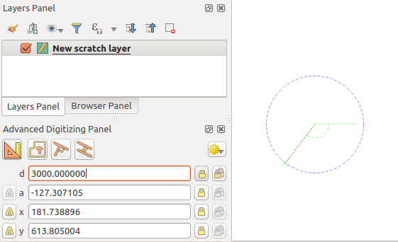
Fig. 12.100 Fixed length segment
You can also constrain the vertex position, setting the angle of the segment. As described before:
Click the a (angle) text box (keyboard shortcut A)
Type the angle value (in degrees)
Press Enter or click the
button on the right to lock it.
A line going through the latest vertex and rotated based on the set angle
appears in the map canvas and a cross on it shows the next vertex
position if you click.
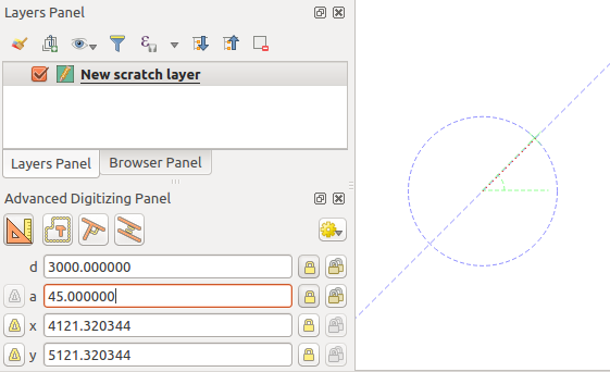
Fig. 12.101 Fixed angle segment
Hint
Pressing Ctrl+<key> or Alt+<key> automatically locks
the target property and puts its value into edit. Modify, press Enter
and you are done. Combined with the Toggle floater,
this can be a real time saver, with keyboard digitizing.
12.3.7.4. Relative reference digitizing
Instead of using absolute values of angles or coordinates, you can also use values relative to the last digitized vertex or segment.
For angles, you can click the  button on the left of the a
text box (or press Shift+A) to toggle relative angles to the previous
segment. With that option on, angles are measured between the last segment
and the mouse pointer.
button on the left of the a
text box (or press Shift+A) to toggle relative angles to the previous
segment. With that option on, angles are measured between the last segment
and the mouse pointer.
For coordinates, click the buttons to the left of the x,
y, z or m text boxes (or press Shift+<key>)
to toggle relative coordinates to the previous vertex. With these options on,
coordinates measurement will consider the last vertex to be the origin of
the set coordinates.
12.3.7.5. Continuous lock
Both in absolute or relative reference digitizing, angle, distance, X, Y, Z
and M constraints can be locked continuously by clicking the  Continuous lock buttons. Using continuous lock allows you to
digitize several points or vertices using the same constraints.
Continuous lock buttons. Using continuous lock allows you to
digitize several points or vertices using the same constraints.
12.3.7.6. Construction mode
You can enable and disable construction mode by clicking on the
Construction mode icon or with the C keyboard
shortcut. While in construction mode, clicking the map canvas won’t add new
vertices, but will capture the clicks’ positions so that you can use them as
reference points to then lock distance, angle or X, Y, Z, M relative values.
In the Construction mode you will find a drop-down menu
where you can choose to:
- Record Construction Guides: All construction steps are
rendered as dashed lines. Each step that you perform is visually represented,
allowing you to trace the construction process. The guides are displayed as
long as Advanced Digitizing remains active.
- Show Construction Guides: Allows you to make construction
guides visible or hidden on the canvas. When enabled, all active guides are displayed,
offering better spatial orientation and precision during the digitizing process.
- Snap to Visible Construction Guides: The guides are snap-able,
allowing you to start new construction steps from any point along the existing guides.
Choose Clear Construction Guides to remove all the guides from the canvas.
As an example, the construction mode can be used to draw some point at an exact distance from an existing point.
With an existing point in the map canvas and the snapping mode correctly
activated, you can easily draw other points at given distances and angles from
it. In addition to the button, you have to activate also the
construction mode by clicking the Construction mode
icon or with the C keyboard shortcut.
Click next to the point from which you want to calculate the distance and click on the d box (D shortcut) type the desired distance and press Enter to lock the mouse position in the map canvas:
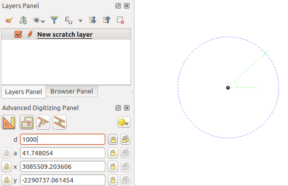
Fig. 12.102 Distance from point
Before adding the new point, press C to exit the construction mode. Now, you can click on the map canvas, and the point will be placed at the distance entered.
You can also use the angle constraint to, for example, create another point at
the same distance of the original one, but at a particular angle from the newly
added point. Click the Construction mode icon or with the
C keyboard shortcut to enter construction mode. Click the recently added
point, and then the other one to set a direction segment. Then, click on the
d text box (D shortcut) type the desired distance and press
Enter. Click the a text box (A shortcut) type the
angle you want and press Enter. The mouse position will be locked both in
distance and angle.
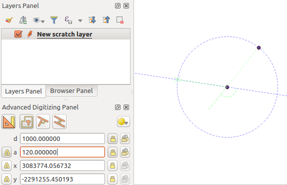
Fig. 12.103 Distance and angle from points
Before adding the new point, press C to exit the construction mode. Now, you can click on the map canvas, and the point will be placed at the distance and angle entered. Repeating the process, several points can be added.
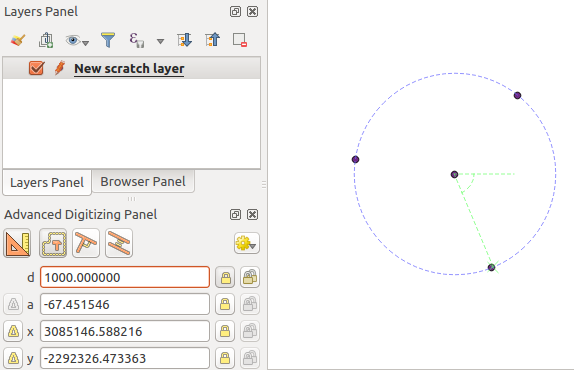
Fig. 12.104 Points at given distance and angle
12.3.7.7. Parallel and perpendicular lines
All the tools described above can be combined with the
Perpendicular and Parallel tools. These two tools
allow drawing segments perfectly perpendicular or parallel to another segment.
The target segment can be on another layer, another feature within the layer or
the feature being digitized (requires self-snapping option).
To draw a perpendicular segment:
First add one of the segment vertices.
Click the
Perpendicular icon
(keyboard shortcut P) to activate it.Click on the segment that you want to be perpendicular to.
A virtual dotted line perpendicular to the segment through the previous vertex appears. The angle property is locked, constraining the next vertex on that line and, a cross indicates the projected position of the cursor on the line. Click to place the new vertex.
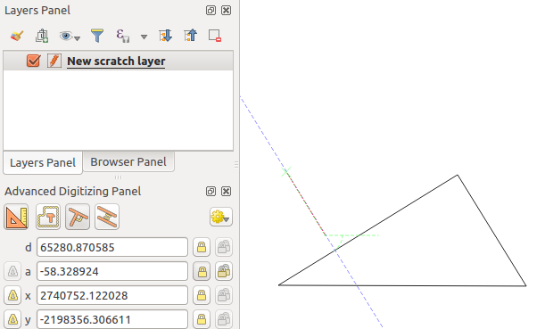
Fig. 12.105 Perpendicular digitizing
To draw a parallel segment, the steps are the same except that you need to
click on the Parallel icon (keyboard shortcut P twice).
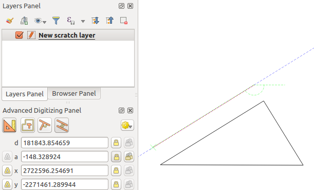
Fig. 12.106 Parallel digitizing
These two tools just find the right angle of the perpendicular and parallel angle and lock this parameter during your editing. Unlock the angle parameter to cancel their use in the middle of the process.
12.3.7.8. 2-circle point intersection
To add a vertex at the intersection of two circles, follow these steps:
Click the
2-circle Point Intersection icon.A dialog will open where you can define the parameters for Circle #1 and Circle #2.
Click on the map canvas, and the tool will automatically calculate the X and Y coordinates for the centers of both circles.
Enter the distance d for each circle.
The tool will calculate and display the two intersection points of the circles.
Click one of the intersection points to add the new vertex.

Fig. 12.107 2-circle Point Intersection
12.3.8. The Processing in-place layer modifier
The Processing menu provides access to a large set of tools to analyze and create new features based on the properties of the input features or their relations with other features (within the same layer or not). While the common behavior is to create new layers as outputs, some algorithms also allow modifications to the input layer. This is a handy way to automate multiple features modification using advanced and complex operations.
To edit features in-place:
Select the layer to edit in the Layers panel.
Select the concerned features. You can skip this step, in which case the modification will apply to the whole layer.
Press the
 Edit Features In-Place button at the top
of the Processing toolbox. The list of algorithms
is filtered, showing only those compatible with in-place modifications, i.e.:
Edit Features In-Place button at the top
of the Processing toolbox. The list of algorithms
is filtered, showing only those compatible with in-place modifications, i.e.:They work at the feature source and not at the layer level.
They do not change the layer structure, e.g. adding or removing fields.
They do not change the geometry type, e.g. from line to point layer.
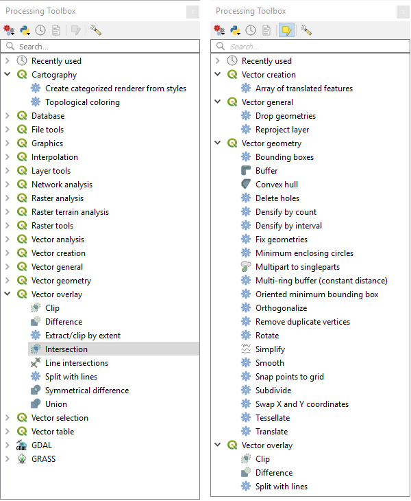
Fig. 12.108 Processing algorithms: all (left) vs polygon in-place editors (right)
Find the algorithm you’d like to run and double-click it.
Note
If the algorithm does not need any additional user-set parameters (excluding the usual input and output layer parameters), then the algorithm is run immediately without any dialog popup.
If parameters other than the usual input or output layers are needed, the algorithm dialog pops up. Fill in the required information.
Click Modify Selected Features or Modify All Features depending on whether there’s an active selection.
Changes are applied to the layer and placed in the edit buffer: the layer is indeed toggled to editing mode with unsaved modification as indicated by the
 icon next to the layer name.
As usual, press
Save layer edits to commit the changes in
the layer. You can also press Undo to rollback the whole
modification.