10.4. Creating 3D Symbols and Materials
The Style Manager helps you create and store 3D symbols and materials for every geometry type to render in the 3D map view.
As of the other items, enable the  3D Symbols tab and expand the
  button menu to create:
Or click the Materials tab and expand the
button to select a material type.
10.4.1. Point Layers
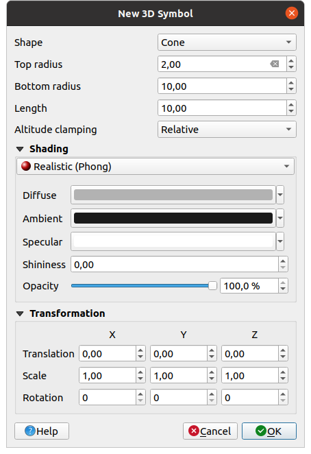
Fig. 10.38 Properties of a 3D point symbol
You can define different types of 3D Shape to use for point symbols. They are mainly defined by their dimensions whose unit refers to the CRS of the project. Available types are:
Sphere defined by a Radius
Cylinder defined by a Radius and Length
Cube defined by a Size
Cone defined by a Top radius, a Bottom radius and a Length
Plane defined by a Size
Torus defined by a Radius and a Minor radius
3D Model, using a 3D model file: supported formats include wavefront
.obj,.glTFand.fbx. Models can be a file on disk, a remote URL or embedded in the project. Community-created models are shared on the QGIS Hub. When placing 3D model symbol, QGIS needs to know the axis conventions used when the model was created. Two settings control this:Up axis defines the axis that is considered as vertical (i.e., the one used for height). Default is Z.
Forward axis defines the axis that is considered as forward (i.e., the one used for orientation). Default is Y.
Billboard, defined by the Billboard height and the Billboard symbol (usually based on a marker symbol). The symbol will have a stable size. Convenient for visualizing 3D point clouds Shapes.
The Altitude clamping can be set to Absolute, Relative or Terrain. The Absolute setting can be used when height values of the 3d vectors are provided as absolute measures from 0. Relative and Terrain add given elevation values to the underlying terrain elevation.
The shading properties can be defined.
Under the Transformations frame, you can apply affine transformation to the symbol:
Translation to move objects in x, y and z axis.
Scale to resize the 3D shapes
Rotation around the x-, y- and z-axis.
10.4.2. Line layers
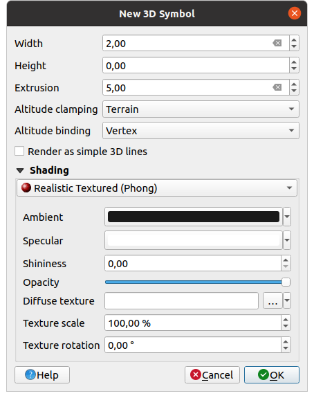
Fig. 10.39 Properties of a 3D line symbol
Beneath the Width and Offset settings you can define the Extrusion of the vector lines. If the lines do not have z-values, you can define the 3d volumes with this setting.
With the Altitude clamping you define the position of the 3D lines relative to the underlying terrain surface, if you have included raster elevation data or other 3D vectors.
The Altitude binding defines how the feature is clamped to the terrain. Either every Vertex of the feature will be clamped to the terrain or this will be done by the Centroid.
It is possible to
 Render as simple 3D lines.
The shading properties can be defined.
10.4.3. Polygon Layers
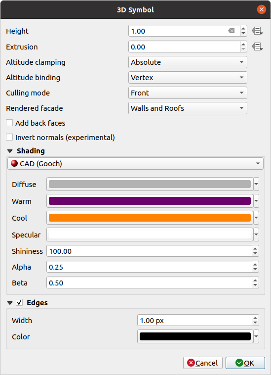
Fig. 10.40 Properties of a 3D polygon symbol
As for the other ones, Offset can be defined in CRS units. You can also use the
 button to overwrite the value with a custom
expression, a variable or an entry of the attribute table
button to overwrite the value with a custom
expression, a variable or an entry of the attribute tableAgain, Extrusion is possible for missing z-values. Also for the extrusion you can use the
button in order to use the values of
the vector layer and have different results for each polygon: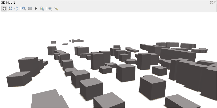
Fig. 10.41 Data Defined Extrusion
The Altitude clamping, Altitude binding can be defined as explained above.
The Culling mode to apply to the symbol; it can be:
No Culling: this can help to avoid seemingly missing surfaces when polygonZ/multipatch data do not have consistent ordering of vertices (e.g. all clock-wise or counter clock-wise)
Front
or Back
The Rendered facade determines the faces to display. Possible values are
Walls,
Roof, and Floor.
The checkboxes allow selecting any combination of these values.- Add back faces: for each triangle, creates both front and
back face with correct normals - at the expense of increased number of vertex data.
This option can be used to fix shading issues (e.g., due to data with inconsistent
order of vertices).
- Invert normals (experimental): can be useful for fixing
clockwise/counter-clockwise face vertex orders
The shading properties can be defined.
Display of the
Edges of the symbols can be enabled
and assigned a Width and Color.
Hint
Combination for best rendering of 3D data
Culling mode, Add back faces and Invert normals
are all meant to fix the look of 3D data if it does not look right.
Typically when loading some data, it is best to first try culling mode=back
and add back faces=disabled - it is the most efficient.
If the rendering does not look correct, try add back faces=enabled and
keep culling mode=no culling. Other combinations are more advanced and
useful only in some scenarios based on how mixed up is the input dataset.
10.4.4. Shading the texture
Shading helps you reveal 3d details of objects which may otherwise be hidden due to the scene’s lighting. Ultimately, it’s an easier material to work with as you don’t need to worry about setting up appropriate scene lighting in order to visualise features.
Various techniques of shading are used in QGIS and their availability depends on the geometry type of the symbol:
Physically Based: renders materials that respond naturally to light, making objects look like real-world materials. Available options are:
Base color: allows users to put base color on surface.
Metalness: sets how metallic the surface appears.
Roughness: controls how rough or smooth the surface is.
Reflectance: controls how much light the surface reflects.
Anisotropy: creates directional reflections that align with the direction specified in Anisotropy direction.
Clear coat strength: controls the intensity of the clear coat layer. Higher values create a stronger glossy appearance, lower values create a more subtle protective layer.
Clear coat roughness: controls the roughness of the clear coat surface. Higher values create a matte clear coat, lower values create a shiny, glossy clear coat.
Emission: an optional setting where users can select solid emission color for metal rough material. Useful for creating emissive solid color material that are not impacted by scene lighting. Adjust the Emission strength value to control the intensity of the light. Check
No Emission if you want materials which are dependent on lighting.
Use the Opacity slider to adjust transparency.
Physically Based (with textures): same as the Physically Based, but users can input more complex texture maps. Available options are:
Base color texture: represents color, pattern, visual detail of the material.
Metalness texture: applies metallic material to the surface.
Roughness texture: defines surface roughness.
Normal texture: adds details to the material. For example: bumps, grooves, scratch and grain.
Height (displacement) texture: displaces geometry to add surface depth, making it appear more realistic. Set the Height texture strength to modify the depth effect as needed.
Ambient occlusion texture: a grayscale image that adds soft shadows to corners, gaps, and areas where objects are close together, making it look more realistic.
Emission texture: adds emissive objects to the surface. To brighten the objects, increase the Emission strength.
Set the desired transparency with the Opacity slider. To transform the texture, adjust Texture scale and Texture rotation as desired.

Fig. 10.42 Physically based (with textures) configuration.
CAD (Gooch): this technique allows shading to occur only in mid-tones so that edge lines and highlights remain visually prominent. Along with the Diffuse, Specular, Shininess options, you need to provide a Warm color (for surface facing toward the light) and a Cool color (for the ones facing away). Also, the relative contributions to the cool and warm colors by the diffuse color are controlled by Alpha and Beta properties respectively. See also Gooch shading.
Legacy (Phong): describes the way a surface reflects light as a combination of the Diffuse reflection of rough surfaces with the Specular reflection of shiny surfaces (Shininess). It also includes an Ambient option to account for the small amount of light that is scattered about the entire scene. Use the Opacity slider to render semi-transparent objects in 3D. Read more at Phong reflection description.
Legacy Textured (Phong): same as the Legacy (Phong) except that an image is used as Diffuse Texture. The image can be a file on disk, a remote URL or embedded in the project. To transform the texture, adjust the Texture scale, Texture rotation or Texture offset as needed. Use the Opacity slider to render semi-transparent objects in 3D.
Single Color (Unlit): allows user to apply single color that does not interact with lights.
10.4.5. Application example
To go through the settings explained above you can have a look at https://app.merginmaps.com/projects/saber/luxembourg/tree.