23.4.3. Stream Network Analysis
23.4.3.1. Connect down
23.4.3.1.1. Description
23.4.3.1.2. Parameters
D8 flow directions[raster]A grid of D8 flow directions which are defined, for each cell, as the direction of the one of its eight adjacent or diagonal neighbors with the steepest downward slope. This grid can be obtained as the output of the “D8 Flow Directions” tool.
D8 contribution area [raster]
Watershed [raster]
Grid cells move to downstream [number]
Outlets[vector: point]Optional
A point shape file defining outlets of interest. If this input file is used, only the area upslope of these outlets will be evaluated by the tool.
23.4.3.1.3. Outputs
Extreme Upslope Values Grid[raster]A grid of the maximum/minimum upslope values.
Algorithm ID: taudem:connectdown
import processing
processing.run("algorithm_id", {parameter_dictionary})
The algorithm id is displayed when you hover over the algorithm in the Processing Toolbox. The parameter dictionary provides the parameter NAMEs and values. See Using processing algorithms from the console for details on how to run processing algorithms from the Python console.
23.4.3.2. D8 Extreme Upslope Value
23.4.3.2.1. Description
Evaluates the extreme (either maximum or minimum) upslope value from an input grid based on the D8 flow model. This is intended initially for use in stream raster generation to identify a threshold of the slope times area product that results in an optimum (according to drop analysis) stream network.
If the optional outlet point shapefile is used, only the outlet cells and the cells upslope (by the D8 flow model) of them are in the domain to be evaluated.
By default, the tool checks for edge contamination. This is defined as the possibility that a result may be underestimated due to grid cells outside of the domain not being counted. This occurs when drainage is inwards from the boundaries or areas with “no data” values for elevation. The algorithm recognizes this and reports “no data” for the result for these grid cells. It is common to see streaks of “no data” values extending inwards from boundaries along flow paths that enter the domain at a boundary. This is the desired effect and indicates that the result for these grid cells is unknown due to it being dependent on terrain outside of the domain of data available. Edge contamination checking may be turned off in cases where you know this is not an issue or want to ignore these problems, if for example, the DEM has been clipped along a watershed outline.
23.4.3.2.2. Parameters
D8 Flow Directions Grid[raster]A grid of D8 flow directions which are defined, for each cell, as the direction of the one of its eight adjacent or diagonal neighbors with the steepest downward slope. This grid can be obtained as the output of the “D8 Flow Directions” tool.
Upslope Values Grid[raster]This is the grid of values of which the maximum or minimum upslope value is selected. The values most commonly used are the slope times area product needed when generating stream rasters according to drop analysis.
Outlets Shapefile[vector: point]Optional
A point shape file defining outlets of interest. If this input file is used, only the area upslope of these outlets will be evaluated by the tool.
Check for edge contamination[boolean]A flag that indicates whether the tool should check for edge contamination.
Default: True
Use max upslope value[boolean]A flag to indicate whether the maximum or minimum upslope value is to be calculated.
Default: True
23.4.3.2.3. Outputs
Extreme Upslope Values Grid[raster]A grid of the maximum/minimum upslope values.
Algorithm ID: taudem:d8flowpathextremeup
import processing
processing.run("algorithm_id", {parameter_dictionary})
The algorithm id is displayed when you hover over the algorithm in the Processing Toolbox. The parameter dictionary provides the parameter NAMEs and values. See Using processing algorithms from the console for details on how to run processing algorithms from the Python console.
23.4.3.3. Gage Watershed
23.4.3.3.1. Description
Calculates Gage Watersheds Grid. Each grid cell is labeled with the identifier
(from column id) of the gage to which it drains directly without passing
through any other gages.
23.4.3.3.2. Parameters
D8 Flow Directions Grid[raster]A grid of D8 flow directions which are defined, for each cell, as the direction of the one of its eight adjacent or diagonal neighbors with the steepest downward slope. This grid can be obtained as the output of the “D8 Flow Directions” tool.
Gages Shapefile[vector: point]A point shapefile defining the gages to which watersheds will be delineated. This shapefile should have a colmun
id. Grid cells draining directly to each point in this shapefile will be labeled with this id.
23.4.3.3.3. Outputs
Gage Watershed Grid[raster]A grid identifies each gage watershed. Each grid cell is labeled with the identifier (from column
id) of the gage to which it drains directly without passing through any other gages.Downstream Identifiers File[file]Text file giving watershed downslope connectivity
Algorithm ID: taudem:gagewatershed
import processing
processing.run("algorithm_id", {parameter_dictionary})
The algorithm id is displayed when you hover over the algorithm in the Processing Toolbox. The parameter dictionary provides the parameter NAMEs and values. See Using processing algorithms from the console for details on how to run processing algorithms from the Python console.
23.4.3.4. Length Area Stream Source
23.4.3.4.1. Description
Creates an indicator grid (1, 0) that evaluates A >= (M)(Ly) based on upslope
path length, D8 contributing area grid inputs, and parameters M and y.
This grid indicates likely stream source grid cells. This is an experimental
method with theoretical basis in Hack’s law which states that for streams
L ~ A 0.6. However for hillslopes with parallel flow L ~ A. So a transition
from hillslopes to streams may be represented by L ~ A 0.8 suggesting
identifying grid cells as stream cells if A > M (L (1/0.8)).
23.4.3.4.2. Parameters
Length Grid[raster]A grid of the maximum upslope length for each cell. This is calculated as the length of the flow path from the furthest cell that drains to each cell. Length is measured between cell centers taking into account cell size and whether the direction is adjacent or diagonal. It is this length (
L) that is used in the formula,A >(M)(Ly), to determine which cells are considered stream cells. This grid can be obtained as an output from the “Grid Network” tool.Contributing Area Grid[raster]A grid of contributing area values for each cell that were calculated using the D8 algorithm. The contributing area for a cell is the sum of its own contribution plus the contribution from all upslope neighbors that drain to it, measured as a number of cells. This grid is typically obtained as the output of the “D8 Contributing Area” tool. In this tool, it is the contributing area (
A) that is compared in the formulaA > (M)(Ly)to determine the transition to a stream.Threshold[number]The multiplier threshold (
M) parameter which is used in the formula:A > (M)(Ly), to identify the beginning of streams.Default: 0.03
Exponent[number]The exponent (
y) parameter which is used in the formula:A > (M)(Ly), to identify the beginning of streams. In branching systems, Hack’s law suggests thatL = 1/M A(1/y)with1/y = 0.6(or 0.56) (yabout 1.7). In parallel flow systemsLis proportional toA(yabout 1). This method tries to identify the transition between these two paradigms by using an exponentysomewhere in between (yabout 1.3).Default: 1.3
23.4.3.4.3. Outputs
Stream Source Grid[raster]An indicator grid (1,0) that evaluates A >= (M)(L^y), based on the maximum upslope path length, the D8 contributing area grid inputs, and parameters
Mandy. This grid indicates likely stream source grid cells.
Algorithm ID: taudem:lengtharea
import processing
processing.run("algorithm_id", {parameter_dictionary})
The algorithm id is displayed when you hover over the algorithm in the Processing Toolbox. The parameter dictionary provides the parameter NAMEs and values. See Using processing algorithms from the console for details on how to run processing algorithms from the Python console.
23.4.3.5. Move Outlets To Streams
23.4.3.5.1. Description
Moves outlet points that are not aligned with a stream cell from a stream raster grid, downslope along the D8 flow direction until a stream raster cell is encountered, the “max_dist” number of grid cells are examined, or the flow path exits the domain (i.e. a “no data” value is encountered for the D8 flow direction). The output file is a new outlets shapefile where each point has been moved to coincide with the stream raster grid, if possible. A field “dist_moved” is added to the new outlets shapefile to indicate the changes made to each point. Points that are already on a stream cell are not moved and their “dist_moved” field is assigned a value 0. Points that are initially not on a stream cell are moved by sliding them downslope along the D8 flow direction until one of the following occurs: a) A stream raster grid cell is encountered before traversing the “max_dist” number of grid cells. In which case, the point is moved and the “dist_moved” field is assigned a value indicating how many grid cells the point was moved. b) More than the “max_number” of grid cells are traversed, or c) the traversal ends up going out of the domain (i.e., a “no data” D8 flow direction value is encountered). In which case, the point is not moved and the “dist_moved” field is assigned a value of -1.
23.4.3.5.2. Parameters
D8 Flow Direction Grid[raster]A grid of D8 flow directions which are defined, for each cell, as the direction of the one of its eight adjacent or diagonal neighbors with the steepest downward slope. This grid can be obtained as the output of the “D8 Flow Directions” tool.
Stream Raster Grid[raster]This output is an indicator grid (1, 0) that indicates the location of streams, with a value of 1 for each of the stream cells and 0 for the remainder of the cells. This file is produced by several different tools in the “Stream Network Analysis” toolset.
Outlets Shapefile[vector: point]A point shape file defining points of interest or outlets that should ideally be located on a stream, but may not be exactly on the stream due to the fact that the shapefile point locations may not have been accurately registered with respect to the stream raster grid.
Maximum Number of Grid Cells to traverse[number]This input parameter is the maximum number of grid cells that the points in the input outlet shapefile will be moved before they are saved to the output outlet shapefile.
Default: 50
23.4.3.5.3. Outputs
Output Outlet Shapefile[vector: point]A point shape file defining points of interest or outlets. This file has one point in it for each point in the input outlet shapefile. If the original point was located on a stream, then the point was not moved. If the original point was not on a stream, the point was moved downslope according to the D8 flow direction until it reached a stream or the maximum distance had been reached. This file has an additional field “dist_moved” added to it which is the number of cells that the point was moved. This field is 0 if the cell was originally on a stream, -1 if it was not moved because there was not a stream within the maximum distance, or some positive value if it was moved.
Algorithm ID: taudem:moveoutletstostreams
import processing
processing.run("algorithm_id", {parameter_dictionary})
The algorithm id is displayed when you hover over the algorithm in the Processing Toolbox. The parameter dictionary provides the parameter NAMEs and values. See Using processing algorithms from the console for details on how to run processing algorithms from the Python console.
23.4.3.6. Peuker Douglas
23.4.3.6.1. Description
Creates an indicator grid (1, 0) of upward curved grid cells according to the Peuker and Douglas algorithm.
With this tool, the DEM is first smoothed by a kernel with weights at the center, sides, and diagonals. The Peuker and Douglas (1975) method (also explained in Band, 1986), is then used to identify upwardly curving grid cells. This technique flags the entire grid, then examines in a single pass each quadrant of 4 grid cells, and unflags the highest. The remaining flagged cells are deemed “upwardly curved”, and when viewed, resemble a channel network. This proto-channel network generally lacks connectivity and requires thinning, issues that were discussed in detail by Band (1986).
23.4.3.6.2. Parameters
Elevation Grid[raster]A grid of elevation values. This is usually the output of the “Pit Remove” tool, in which case it is elevations with pits removed.
Center Smoothing Weight[number]The center weight parameter used by a kernel to smooth the DEM before the tool identifies upwardly curved grid cells.
Default: 0.4
Side Smoothing Weight[number]The side weight parameter used by a kernel to smooth the DEM before the tool identifies upwardly curved grid cells.
Default: 0.1
Diagonal Smoothing Weight[number]The diagonal weight parameter used by a kernel to smooth the DEM before the tool identifies upwardly curved grid cells.
Default: 0.05
23.4.3.6.3. Outputs
Stream Source Grid[raster]An indicator grid (1, 0) of upward curved grid cells according to the Peuker and Douglas algorithm, and if viewed, resembles a channel network. This proto-channel network generally lacks connectivity and requires thinning, issues that were discussed in detail by Band (1986).
23.4.3.6.4. See also
Band, L. E., (1986), “Topographic partition of watersheds with digital elevation models”, Water Resources Research, 22(1): 15-24.
Peuker, T. K. and D. H. Douglas, (1975), “Detection of surface-specific points by local parallel processing of discrete terrain elevation data”, Comput. Graphics Image Process., 4: 375-387.
Algorithm ID: taudem:peukerdouglas
import processing
processing.run("algorithm_id", {parameter_dictionary})
The algorithm id is displayed when you hover over the algorithm in the Processing Toolbox. The parameter dictionary provides the parameter NAMEs and values. See Using processing algorithms from the console for details on how to run processing algorithms from the Python console.
23.4.3.7. Peuker Douglas stream
23.4.3.7.1. Description
23.4.3.7.2. Parameters
23.4.3.7.3. Outputs
Stream source[raster]An indicator grid (1, 0) of upward curved grid cells according to the Peuker and Douglas algorithm, and if viewed, resembles a channel network. This proto-channel network generally lacks connectivity and requires thinning, issues that were discussed in detail by Band (1986).
Algorithm ID: taudem:peukerdouglasstreamdef
import processing
processing.run("algorithm_id", {parameter_dictionary})
The algorithm id is displayed when you hover over the algorithm in the Processing Toolbox. The parameter dictionary provides the parameter NAMEs and values. See Using processing algorithms from the console for details on how to run processing algorithms from the Python console.
23.4.3.8. Slope Area Combination
23.4.3.8.1. Description
Creates a grid of slope-area values = (Sm) (An) based on slope and specific
catchment area grid inputs, and parameters m and n. This tool is intended
for use as part of the slope-area stream raster delineation method.
23.4.3.8.2. Parameters
Slope Grid[raster]This input is a grid of slope values. This grid can be obtained from the “D-Infinity Flow Directions” tool.
Contributing Area Grid[raster]A grid giving the specific catchment area for each cell taken as its own contribution (grid cell length or summation of weights) plus the proportional contribution from upslope neighbors that drain in to it. This grid is typically obtained from the “D-Infinity Contributing Area” tool.
Slope Exponent[number]The slope exponent (
m) parameter which will be used in the formula:(Sm)(An), that is used to create the slope-area grid.Default: 2
Area Exponent[number]The area exponent (
n) parameter which will be used in the formula:(Sm)(An), that is used to create the slope-area grid.Default: 1
23.4.3.8.3. Outputs
Slope Area Grid[raster]A grid of slope-area values =
(Sm)(An)calculated from the slope grid, specific catchment area grid,mslope exponent parameter, andnarea exponent parameter.
Algorithm ID: taudem:slopearea
import processing
processing.run("algorithm_id", {parameter_dictionary})
The algorithm id is displayed when you hover over the algorithm in the Processing Toolbox. The parameter dictionary provides the parameter NAMEs and values. See Using processing algorithms from the console for details on how to run processing algorithms from the Python console.
23.4.3.9. Slope area stream definition
23.4.3.9.1. Description
Creates a grid of slope-area values = (Sm) (An) based on slope and specific
catchment area grid inputs, and parameters m and n. This tool is intended
for use as part of the slope-area stream raster delineation method.
23.4.3.9.2. Parameters
D8 flow directions [raster]
D-infinity Contributing Area[raster]A grid giving the specific catchment area for each cell taken as its own contribution (grid cell length or summation of weights) plus the proportional contribution from upslope neighbors that drain in to it. This grid is typically obtained from the “D-Infinity Contributing Area” tool.
Slope[raster]This input is a grid of slope values. This grid can be obtained from the “D-Infinity Flow Directions” tool.
Mask grid [raster]
Outlets [vector: point]
Pit-filled grid for drop analysis [raster]
D8 contributing area for drop analysis [raster]
Slope Exponent[number]The slope exponent (
m) parameter which will be used in the formula:(Sm)(An), that is used to create the slope-area grid.Default: 2
Area Exponent[number]The area exponent (
n) parameter which will be used in the formula:(Sm)(An), that is used to create the slope-area grid.Default: 1
Accumulation threshold [number]
Minimum threshold [number]
Maximum threshold [number]
Number of drop thresholds [number]
Type of threshold step [enumeration].
Options:
0 — Logarithmic
1 — Linear
Default: 0
Check for edge contamination [boolean]
Select threshold by drop analysis [boolean]
23.4.3.9.3. Outputs
Stream raster [raster]
Slope area[raster]A grid of slope-area values =
(Sm)(An)calculated from the slope grid, specific catchment area grid,mslope exponent parameter, andnarea exponent parameter.
Maximum upslope [raster]
Drop analysis [file]
Algorithm ID: taudem:slopeareastreamdef
import processing
processing.run("algorithm_id", {parameter_dictionary})
The algorithm id is displayed when you hover over the algorithm in the Processing Toolbox. The parameter dictionary provides the parameter NAMEs and values. See Using processing algorithms from the console for details on how to run processing algorithms from the Python console.
23.4.3.10. Stream Definition By Threshold
23.4.3.10.1. Description
Operates on any grid and outputs an indicator (1, 0) grid identifying cells with
input values >= the threshold value. The standard use is to use an accumulated
source area grid to as the input grid to generate a stream raster grid as the
output. If you use the optional input mask grid, it limits the domain being
evaluated to cells with mask values >= 0. When you use a D-infinity contributing
area grid (*sca) as the mask grid, it functions as an edge contamination
mask. The threshold logic is:
src = ((ssa >= thresh) & (mask >= s0)) ? 1:0
23.4.3.10.2. Parameters
Accumulated Stream Source Grid[raster]This grid nominally accumulates some characteristic or combination of characteristics of the watershed. The exact characteristic(s) varies depending on the stream network raster algorithm being used. This grid needs to have the property that grid cell values are monotonically increasing downslope along D8 flow directions, so that the resulting stream network is continuous. While this grid is often from an accumulation, other sources such as a maximum upslope function will also produce a suitable grid.
Threshold[number]This parameter is compared to the value in the Accumulated Stream Source grid (
*ssa) to determine if the cell should be considered a stream cell. Streams are identified as grid cells for which ssa value is >= this threshold.Default: 100
Mask Grid[raster]Optional
This optional input is a grid that is used to mask the domain of interest and output is only provided where this grid is >= 0. A common use of this input is to use a D-Infinity contributing area grid as the mask so that the delineated stream network is constrained to areas where D-infinity contributing area is available, replicating the functionality of an edge contamination mask.
23.4.3.10.3. Outputs
Stream Raster Grid[raster]This is an indicator grid (1, 0) that indicates the location of streams, with a value of 1 for each of the stream cells and 0 for the remainder of the cells.
Algorithm ID: taudem:threshold
import processing
processing.run("algorithm_id", {parameter_dictionary})
The algorithm id is displayed when you hover over the algorithm in the Processing Toolbox. The parameter dictionary provides the parameter NAMEs and values. See Using processing algorithms from the console for details on how to run processing algorithms from the Python console.
23.4.3.11. Stream definition with drop analysis
23.4.3.11.1. Description
23.4.3.11.2. Parameters
23.4.3.11.3. Outputs
Algorithm ID: taudem:streamdefdropanalysis
import processing
processing.run("algorithm_id", {parameter_dictionary})
The algorithm id is displayed when you hover over the algorithm in the Processing Toolbox. The parameter dictionary provides the parameter NAMEs and values. See Using processing algorithms from the console for details on how to run processing algorithms from the Python console.
23.4.3.12. Stream Drop Analysis
23.4.3.12.1. Description
Applies a series of thresholds (determined from the input parameters) to the
input accumulated stream source grid (*ssa) grid and outputs the results
in the *drp.txt file the stream drop statistics table. This function is
designed to aid in the determination of a geomorphologically objective threshold
to be used to delineate streams. Drop Analysis attempts to select the right
threshold automatically by evaluating a stream network for a range of thresholds
and examining the constant drop property of the resulting Strahler streams.
Basically it asks the question: Is the mean stream drop for first order streams
statistically different from the mean stream drop for higher order streams, using
a T-test. Stream drop is the difference in elevation from the beginning to the
end of a stream defined as the sequence of links of the same stream order. If the
T-test shows a significant difference then the stream network does not obey this
“law” so a larger threshold needs to be chosen. The smallest threshold for which
the T-test does not show a significant difference gives the highest resolution
stream network that obeys the constant stream drop “law” from geomorphology, and
is the threshold chosen for the “objective” or automatic mapping of streams from
the DEM. This function can be used in the development of stream network rasters,
where the exact watershed characteristic(s) that were accumulated in the
accumulated stream source grid vary based on the method being used to determine
the stream network raster.
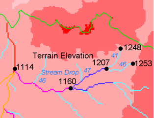
The constant stream drop “law” was identified by Broscoe (1959). For the science behind using this to determine a stream delineation threshold, see Tarboton et al. (1991, 1992), Tarboton and Ames (2001).
23.4.3.12.2. Parameters
D8 Contributing Area Grid[raster]A grid of contributing area values for each cell that were calculated using the D8 algorithm. The contributing area for a cell is the sum of its own contribution plus the contribution from all upslope neighbors that drain to it, measured as a number of cells or the sum of weight loadings. This grid can be obtained as the output of the “D8 Contributing Area” tool. This grid is used in the evaluation of drainage density reported in the stream drop table.
D8 Flow Direction Grid[raster]A grid of D8 flow directions which are defined, for each cell, as the direction of the one of its eight adjacent or diagonal neighbors with the steepest downward slope. This grid can be obtained as the output of the “D8 Flow Directions” tool.
Pit Filled Elevation Grid[raster]A grid of elevation values. This is usually the output of the “Pit Remove” tool, in which case it is elevations with pits removed.
Accumulated Stream Source Grid[raster]This grid must be monotonically increasing along the downslope D8 flow directions. It it compared to a series of thresholds to determine the beginning of the streams. It is often generated by accumulating some characteristic or combination of characteristics of the watershed with the “D8 Contributing Area” tool, or using the maximum option of the “D8 Flow Path Extreme” tool. The exact method varies depending on the algorithm being used.
Outlets Shapefile[vector: point]A point shapefile defining the outlets upstream of which drop analysis is performed.
Minimum Threshold[number]This parameter is the lowest end of the range searched for possible threshold values using drop analysis. This technique looks for the smallest threshold in the range where the absolute value of the t-statistic is less than 2. For the science behind the drop analysis see Tarboton et al. (1991, 1992), Tarboton and Ames (2001).
Default: 5
Maximum Threshold[number]This parameter is the highest end of the range searched for possible threshold values using drop analysis. This technique looks for the smallest threshold in the range where the absolute value of the t-statistic is less than 2. For the science behind the drop analysis see Tarboton et al. (1991, 1992), Tarboton and Ames (2001).
Default: 500
Number of Threshold Values[number]The parameter is the number of steps to divide the search range into when looking for possible threshold values using drop analysis. This technique looks for the smallest threshold in the range where the absolute value of the t-statistic is less than 2. For the science behind the drop analysis see Tarboton et al. (1991, 1992), Tarboton and Ames (2001).
Default: 10
Spacing for Threshold Values[enumeration]This parameter indicates whether logarithmic or linear spacing should be used when looking for possible threshold values using drop analysis.
Options:
0 — Logarithmic
1 — Linear
Default: 0
23.4.3.12.3. Outputs
D-Infinity Drop to Stream Grid[file]This is a comma delimited text file with the following header line:
- ::
Threshold,DrainDen,NoFirstOrd,NoHighOrd,MeanDFirstOrd,MeanDHighOrd,StdDevFirstOrd,StdDevHighOrd,T
The file then contains one line of data for each threshold value examined, and then a summary line that indicates the optimum threshold value. This technique looks for the smallest threshold in the range where the absolute value of the t-statistic is less than 2. For the science behind the drop analysis, see Tarboton et al. (1991, 1992), Tarboton and Ames (2001).
Algorithm ID: taudem:dropanalysis
import processing
processing.run("algorithm_id", {parameter_dictionary})
The algorithm id is displayed when you hover over the algorithm in the Processing Toolbox. The parameter dictionary provides the parameter NAMEs and values. See Using processing algorithms from the console for details on how to run processing algorithms from the Python console.
23.4.3.12.4. See also
Broscoe, A. J., (1959), “Quantitative analysis of longitudinal stream profiles of small watersheds”, Office of Naval Research, Project NR 389-042, Technical Report No. 18, Department of Geology, Columbia University, New York.
Tarboton, D. G., R. L. Bras and I. Rodriguez-Iturbe, (1991), “On the Extraction of Channel Networks from Digital Elevation Data”, Hydrologic Processes, 5(1): 81-100.
Tarboton, D. G., R. L. Bras and I. Rodriguez-Iturbe, (1992), “A Physical Basis for Drainage Density”, Geomorphology, 5(1/2): 59-76.
Tarboton, D. G. and D. P. Ames, (2001), “Advances in the mapping of flow networks from digital elevation data”, World Water and Environmental Resources Congress, Orlando, Florida, May 20-24, ASCE, https://www.researchgate.net/publication/2329568_Advances_in_the_Mapping_of_Flow_Networks_From_Digital_Elevation_Data.
23.4.3.13. Stream Reach and Watershed
23.4.3.13.1. Description
This tool produces a vector network and shapefile from the stream raster grid. The flow direction grid is used to connect flow paths along the stream raster. The Strahler order of each stream segment is computed. The subwatershed draining to each stream segment (reach) is also delineated and labeled with the value identifier that corresponds to the WSNO (watershed number) attribute in the Stream Reach Shapefile.
This tool orders the stream network according to the Strahler ordering system. Streams that don’t have any other streams draining in to them are order 1. When two stream reaches of different order join the order of the downstream reach is the order of the highest incoming reach. When two reaches of equal order join the downstream reach order is increased by 1. When more than two reaches join the downstream reach order is calculated as the maximum of the highest incoming reach order or the second highest incoming reach order + 1. This generalizes the common definition to cases where more than two reaches join at a point. The network topological connectivity is stored in the Stream Network Tree file, and coordinates and attributes from each grid cell along the network are stored in the Network Coordinates file.
The stream raster grid is used as the source for the stream network, and the flow direction grid is used to trace connections within the stream network. Elevations and contributing area are used to determine the elevation and contributing area attributes in the network coordinate file. Points in the outlets shapefile are used to logically split stream reaches to facilitate representing watersheds upstream and downstream of monitoring points. The program uses the attribute field “id” in the outlets shapefile as identifiers in the Network Tree file. This tool then translates the text file vector network representation in the Network Tree and Coordinates files into a shapefile. Further attributes are also evaluated. The program has an option to delineate a single watershed by representing the entire area draining to the Stream Network as a single value in the output watershed grid.
23.4.3.13.2. Parameters
Pit Filled Elevation Grid[raster]A grid of elevation values. This is usually the output of the “Pit Remove” tool, in which case it is elevations with pits removed.
D8 Flow Direction Grid[raster]A grid of D8 flow directions which are defined, for each cell, as the direction of the one of its eight adjacent or diagonal neighbors with the steepest downward slope. This grid can be obtained as the output of the “D8 Flow Directions” tool.
D8 Drainage Area[raster]A grid giving the contributing area value in terms of the number of grid cells (or the summation of weights) for each cell taken as its own contribution plus the contribution from upslope neighbors that drain in to it using the D8 algorithm. This is usually the output of the “D8 Contributing Area” tool and is used to determine the contributing area attribute in the Network Coordinate file.
Stream Raster Grid[raster]An indicator grid indicating streams, by using a grid cell value of 1 on streams and 0 off streams. Several of the “Stream Network Analysis” tools produce this type of grid. The Stream Raster Grid is used as the source for the stream network.
Outlets Shapefile as Network Nodes[vector: point]Optional
A point shape file defining points of interest. If this file is used, the tool will only deliniate the stream network upstream of these outlets. Additionally, points in the Outlets Shapefile are used to logically split stream reaches to facilitate representing watersheds upstream and downstream of monitoring points. This tool REQUIRES THAT THERE BE an integer attribute field “id” in the Outlets Shapefile, because the “id” values are used as identifiers in the Network Tree file.
Delineate Single Watershed[boolean]This option causes the tool to delineate a single watershed by representing the entire area draining to the Stream Network as a single value in the output watershed grid. Otherwise a seperate watershed is delineated for each stream reach. Default is False (seperate watershed).
Default: False
23.4.3.13.3. Outputs
Stream Order Grid[raster]The Stream Order Grid has cells values of streams ordered according to the Strahler order system. The Strahler ordering system defines order 1 streams as stream reaches that don’t have any other reaches draining in to them. When two stream reaches of different order join the order of the downstream reach is the order of the highest incoming reach. When two reaches of equal order join the downstream reach order is increased by 1. When more than two reaches join the downstream reach order is calculated as the maximum of the highest incoming reach order or the second highest incoming reach order + 1. This generalizes the common definition to cases where more than two flow paths reaches join at a point.
Watershed Grid[raster]This output grid identified each reach watershed with a unique ID number, or in the case where the delineate single watershed option was checked, the entire area draining to the stream network is identified with a single ID.
Stream Reach Shapefile[vector: line]This output is a polyline shapefile giving the links in a stream network. The columns in the attribute table are:
LINKNO — Link Number. A unique number associated with each link (segment of channel between junctions). This is arbitrary and will vary depending on number of processes used
DSLINKNO — Link Number of the downstream link. -1 indicates that this does not exist
USLINKNO1 — Link Number of first upstream link. (-1 indicates no link upstream, i.e. for a source link)
USLINKNO2 — Link Number of second upstream link. (-1 indicates no second link upstream, i.e. for a source link or an internal monitoring point where the reach is logically split but the network does not bifurcate)
DSNODEID — Node identifier for node at downstream end of stream reach. This identifier corresponds to the “id” attribute from the Outlets shapefile used to designate nodes
Order — Strahler Stream Order
Length — Length of the link. The units are the horizontal map units of the underlying DEM grid
Magnitude — Shreve Magnitude of the link. This is the total number of sources upstream
DS_Cont_Ar — Drainage area at the downstream end of the link. Generally this is one grid cell upstream of the downstream end because the drainage area at the downstream end grid cell includes the area of the stream being joined
Drop — Drop in elevation from the start to the end of the link
Slope — Average slope of the link (computed as drop/length)
Straight_L — Straight line distance from the start to the end of the link
US_Cont_Ar — Drainage area at the upstream end of the link
WSNO — Watershed number. Cross reference to the
*w.shpand*wgrid files giving the identification number of the watershed draining directly to the linkDOUT_END — Distance to the eventual outlet (i.e. the most downstream point in the stream network) from the downstream end of the link
DOUT_START — Distance to the eventual outlet from the upstream end of the link
DOUT_MID — Distance to the eventual outlet from the midpoint of the link
Network Connectivity Tree[file]This output is a text file that details the network topological connectivity is stored in the Stream Network Tree file. Columns are as follows:
Link Number (Arbitrary — will vary depending on number of processes used)
Start Point Number in Network coordinates (
*coord.dat)file (Indexed from 0)End Point Number in Network coordinates (
*coord.dat) file (Indexed from 0)Next (Downstream) Link Number. Points to Link Number. -1 indicates no links downstream, i.e. a terminal link
First Previous (Upstream) Link Number. Points to Link Number. -1 indicates no upstream links
Second Previous (Upstream) Link Numbers. Points to Link Number. -1 indicates no upstream links. Where only one previous link is -1, it indicates an internal monitoring point where the reach is logically split, but the network does not bifurcate
Strahler Order of Link
Monitoring point identifier at downstream end of link. -1 indicates downstream end is not a monitoring point
Network magnitude of the link, calculated as the number of upstream sources (following Shreve)
Network Coordinates[file]This output is a text file that contains the coordinates and attributes of points along the stream network. Columns are as follows:
X coordinate
Y Coordinate
Distance along channels to the downstream end of a terminal link
Elevation
Contributing area
Algorithm ID: taudem:streamnet
import processing
processing.run("algorithm_id", {parameter_dictionary})
The algorithm id is displayed when you hover over the algorithm in the Processing Toolbox. The parameter dictionary provides the parameter NAMEs and values. See Using processing algorithms from the console for details on how to run processing algorithms from the Python console.