23.4.1. Basic Grid Analysis
23.4.1.1. D-Infinity Contributing Area
23.4.1.1.1. Description
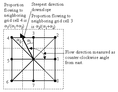
Calculates a grid of specific catchment area which is the contributing area per unit contour length using the multiple flow direction D-infinity approach. D-infinity flow direction is defined as steepest downward slope on planar triangular facets on a block centered grid. The contribution at each grid cell is taken as the grid cell length (or when the optional weight grid input is used, from the weight grid). The contributing area of each grid cell is then taken as its own contribution plus the contribution from upslope neighbors that have some fraction draining to it according to the D-infinity flow model. The flow from each cell either all drains to one neighbor, if the angle falls along a cardinal (0, π/2, π, 3π/2) or ordinal (π/4, 3π/4, 5π/4, 7π/4) direction, or is on an angle falling between the direct angle to two adjacent neighbors. In the latter case the flow is proportioned between these two neighbor cells according to how close the flow direction angle is to the direct angle to those cells. The contour length used here is the grid cell size. The resulting units of the specific catchment area are length units the same as those of the grid cell size.
When the optional weight grid is not used, the result is reported in terms of specific catchment area, the upslope area per unit contour length, taken here as the number of cells times grid cell length (cell area divided by cell length). This assumes that grid cell length is the effective contour length, in the definition of specific catchment area and does not distinguish any difference in contour length dependent upon the flow direction. When the optional weight grid is used, the result is reported directly as a summation of weights, without any scaling.
If the optional outlet point shapefile is used, only the outlet cells and the cells upslope (by the D-infinity flow model) of them are in the domain to be evaluated.
By default, the tool checks for edge contamination. This is defined as the possibility that a contributing area value may be underestimated due to grid cells outside of the domain not being counted. This occurs when drainage is inwards from the boundaries or areas with “no data” values for elevation. The algorithm recognizes this and reports “no data” for the contributing area. It is common to see streaks of “no data” values extending inwards from boundaries along flow paths that enter the domain at a boundary. This is the desired effect and indicates that contributing area for these grid cells is unknown due to it being dependent on terrain outside of the domain of data available. Edge contamination checking may be turned off in cases where you know it is not an issue or want to ignore these problems, if for example, the DEM has been clipped along a watershed outline.
23.4.1.1.2. Parameters
Label |
Name |
Type |
Description |
|---|---|---|---|
D-infinity flow directions |
|
[raster] |
A grid of flow directions based on the D-infinity flow method using the steepest slope of a triangular facet. Flow direction is determined as the direction of the steepest downward slope on the 8 triangular facets of a 3x3 block centered grid. Flow direction is encoded as an angle in radians, counter-clockwise from east as a continuous (floating point) quantity between 0 and 2π. The resulting flow in a grid is then usually interpreted as being proportioned between the two neighboring cells that define the triangular facet with the steepest downward slope. |
Outlets Optional |
|
[vector: point] |
A point shapefile defining the outlets of interest. If this input file is used, only the cells upslope of these outlet cells are considered to be within the domain being evaluated. |
Weight grid Optional |
|
[raster] |
A grid giving contribution to flow for each cell. These contributions (also sometimes referred to as weights or loadings) are used in the contributing area accumulation. If this input file is not used, the result is reported in terms of specific catchment area (the upslope area per unit contour length) taken as the number of cells times grid cell length (cell area divided by cell length). |
Check for edge contamination |
|
[boolean] Default: True |
A flag that indicates whether the tool should check for edge contamination. Edge contamination is defined as the possibility that a contributing area value may be underestimated due to the fact that grid cells outside of the domain have not been evaluated. This occurs when drainage is inwards from the boundaries or areas with NODATA values for elevation. The algorithm recognizes this and reports NODATA for the impated cells. It is common to see streaks of NODATA values extending inwards from boundaries along flow paths that enter the domain at a boundary. This is the desired effect and indicates that contributing area for these grid cells is unknown due to it being dependent on terrain outside of the domain of available data. Edge contamination checking may be turned off in cases where you know this is not an issue, or want to ignore these problems, if for example, the DEM has been clipped along a watershed outline. |
D-infinity specific catchment area |
|
[raster] Default: |
Specification of the output raster. One of:
The file encoding can also be changed here. |
23.4.1.1.3. Outputs
Label |
Name |
Type |
Description |
|---|---|---|---|
D-infinity specific catchment area |
|
[raster] |
A grid of specific catchment area which is the contributing area per unit contour length using the multiple flow direction D-infinity approach. The contributing area of each grid cell is then taken as its own contribution plus the contribution from upslope neighbors that have some fraction draining to it according to the D-infinity flow model. |
Algorithm ID: taudem:areadinf
import processing
processing.run("algorithm_id", {parameter_dictionary})
The algorithm id is displayed when you hover over the algorithm in the Processing Toolbox. The parameter dictionary provides the parameter NAMEs and values. See Using processing algorithms from the console for details on how to run processing algorithms from the Python console.
23.4.1.2. D-Infinity Flow Directions
23.4.1.2.1. Description
Assigns a flow direction based on the D-infinity flow method using the steepest slope of a triangular facet (Tarboton, 1997, “A New Method for the Determination of Flow Directions and Contributing Areas in Grid Digital Elevation Models”, Water Resources Research, 33(2): 309-319). Flow direction is defined as steepest downward slope on planar triangular facets on a block centered grid. Flow direction is encoded as an angle in radians counter-clockwise from east as a continuous (floating point) quantity between 0 and 2π. The flow direction angle is determined as the direction of the steepest downward slope on the eight triangular facets formed in a 3 x 3 grid cell window centered on the grid cell of interest. The resulting flow in a grid is then usually interpreted as being proportioned between the two neighboring cells that define the triangular facet with the steepest downward slope.
A block-centered representation is used with each elevation value taken to represent the elevation of the center of the corresponding grid cell. Eight planar triangular facets are formed between each grid cell and its eight neighbors. Each of these has a downslope vector which when drawn outwards from the center may be at an angle that lies within or outside the 45 degree (π/4 radian) angle range of the facet at the center point. If the slope vector angle is within the facet angle, it represents the steepest flow direction on that facet. If the slope vector angle is outside a facet, the steepest flow direction associated with that facet is taken along the steepest edge. The slope and flow direction associated with the grid cell is taken as the magnitude and direction of the steepest downslope vector from all eight facets. Slope is measured as drop/distance, i.e. tan of the slope angle.
In the case where no slope vectors are positive (downslope), the flow direction is set using the method of Garbrecht and Martz (1997) for the determination of flow across flat areas. This makes flat areas drain away from high ground and towards low ground. The flow path grid to enforce drainage along existing streams is an optional input, and if used, takes precedence over elevations for the setting of flow directions.
The D-infinity flow direction algorithm may be applied to a DEM that has not had its pits filled, but it will then result in “no data” values for the D-infinity flow direction and slope associated with the lowest point of the pit.
23.4.1.2.2. Parameters
Label |
Name |
Type |
Description |
|---|---|---|---|
Pit filled elevation |
|
[raster] |
A grid of elevation values. This is usually the output of the “Pit Remove” tool, in which case it is elevations with pits removed. Pits are low elevation areas in digital elevation models (DEMs) that are completely surrounded by higher terrain. They are generally taken to be artifacts of the digitation process that interfere with the processing of flow across DEMs. So they are removed by raising their elevation to the point where they just drain off the domain. This step is not essential if you have reason to believe that the pits in your DEM are real. If a few pits actually exist and so should not be removed, while at the same time others are believed to be artifacts that need to be removed, the actual pits should have NODATA elevation values inserted at their lowest point. NODATA values serve to define edges of the domain in the flow field, and elevations are only raised to where flow is off an edge, so an internal NODATA value will stop a pit from being removed, if necessary. |
D-infinity flow directions |
|
[raster] Default: |
Specification of the output flow direction raster. One of:
The file encoding can also be changed here. |
D-infinity slope |
|
[raster] Default: |
Specification of the output slope raster. One of:
The file encoding can also be changed here. |
23.4.1.2.3. Outputs
Label |
Name |
Type |
Description |
|---|---|---|---|
D-infinity flow directions |
|
[raster] |
A grid of flow directions based on the D-infinity flow method using the steepest slope of a triangular facet. Flow direction is determined as the direction of the steepest downward slope on the 8 triangular facets of a 3x3 block centered grid. Flow direction is encoded as an angle in radians, counter-clockwise from east as a continuous (floating point) quantity between 0 and 2π. The resulting flow in a grid is then usually interpreted as being proportioned between the two neighboring cells that define the triangular facet with the steepest downward slope. |
D-infinity slope |
|
[raster] |
A grid of slope evaluated using the D-infinity method described in Tarboton, D. G., (1997), “A New Method for the Determination of Flow Directions and Contributing Areas in Grid Digital Elevation Models”, Water Resources Research, 33(2): 309-319. This is the steepest outwards slope on one of eight triangular facets centered at each grid cell, measured as drop/distance, i.e. tan of the slope angle. |
Algorithm ID: taudem:dinfflowdir
import processing
processing.run("algorithm_id", {parameter_dictionary})
The algorithm id is displayed when you hover over the algorithm in the Processing Toolbox. The parameter dictionary provides the parameter NAMEs and values. See Using processing algorithms from the console for details on how to run processing algorithms from the Python console.
23.4.1.3. D8 Contributing Area
23.4.1.3.1. Description
Calculates a grid of contributing areas using the single direction D8 flow model. The contribution of each grid cell is taken as one (or when the optional weight grid is used, the value from the weight grid). The contributing area for each grid cell is taken as its own contribution plus the contribution from upslope neighbors that drain in to it according to the D8 flow model.
If the optional outlet point shapefile is used, only the outlet cells and the cells upslope (by the D8 flow model) of them are in the domain to be evaluated.
By default, the tool checks for edge contamination. This is defined as the possibility that a contributing area value may be underestimated due to grid cells outside of the domain not being counted. This occurs when drainage is inwards from the boundaries or areas with “no data” values for elevation. The algorithm recognizes this and reports “no data” for the contributing area. It is common to see streaks of “no data” values extending inwards from boundaries along flow paths that enter the domain at a boundary. This is the desired effect and indicates that contributing area for these grid cells is unknown due to it being dependent on terrain outside of the domain of data available. Edge contamination checking may be turned off in cases where you know this is not an issue or want to ignore these problems, if for example, the DEM has been clipped along a watershed outline.
23.4.1.3.2. Parameters
Label |
Name |
Type |
Description |
|---|---|---|---|
D8 flow directions |
|
[raster] |
A grid of D8 flow directions which are defined, for each cell, as the direction of the one of its eight adjacent or diagonal neighbors with the steepest downward slope. This grid can be obtained as the output of the “D8 Flow Directions” tool. |
Outlets Optional |
|
[vector: point] |
A point shapefile defining the outlets of interest. If this input file is used, only the cells upslope of these outlet cells are considered to be within the domain being evaluated. |
Weight grid Optional |
|
[raster] |
A grid giving contribution to flow for each cell. These contributions (also sometimes referred to as weights or loadings) are used in the contributing area accumulation. If this input file is not used, the contribution to flow will assumed to be one for each grid cell. |
Check for edge contamination |
|
[boolean] Default: True |
A flag that indicates whether the tool should check for edge contamination. Edge contamination is defined as the possibility that a contributing area value may be underestimated due to the fact that grid cells outside of the domain have not been evaluated. This occurs when drainage is inwards from the boundaries or areas with NODATA values for elevation. The algorithm recognizes this and reports NODATA for the impated cells. It is common to see streaks of NODATA values extending inwards from boundaries along flow paths that enter the domain at a boundary. This is the desired effect and indicates that contributing area for these grid cells is unknown due to it being dependent on terrain outside of the domain of available data. Edge contamination checking may be turned off in cases where you know this is not an issue, or want to ignore these problems, if for example, the DEM has been clipped along a watershed outline. |
D8 specific catchment area |
|
[raster] Default: |
Specification of the output raster. One of:
The file encoding can also be changed here. |
23.4.1.3.3. Outputs
Label |
Name |
Type |
Description |
|---|---|---|---|
D8 specific catchment area |
|
[raster] |
A grid of contributing area values calculated as the cells own contribution plus the contribution from upslope neighbors that drain in to it according to the D8 flow model. |
Algorithm ID: taudem:aread8
import processing
processing.run("algorithm_id", {parameter_dictionary})
The algorithm id is displayed when you hover over the algorithm in the Processing Toolbox. The parameter dictionary provides the parameter NAMEs and values. See Using processing algorithms from the console for details on how to run processing algorithms from the Python console.
23.4.1.4. D8 Flow Directions
23.4.1.4.1. Description
Creates 2 grids. The first contains the flow direction from each grid cell to one of its adjacent or diagonal neighbors, calculated using the direction of steepest descent. The second contain the slope, as evaluated in the direction of steepest descent, and is reported as drop/distance, i.e. tan of the angle. Flow direction is reported as NODATA for any grid cell adjacent to the edge of the DEM domain, or adjacent to a NODATA value in the DEM. In flat areas, flow directions are assigned away from higher ground and towards lower ground using the method of Garbrecht and Martz (1997). The D8 flow direction algorithm may be applied to a DEM that has not had its pits filled, but it will then result in NODATA values for flow direction and slope at the lowest point of each pit.
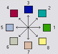
D8 Flow Direction Coding:
1 — East
2 — Northeast
3 — North
4 — Northwest
5 — West
6 — Southwest
7 — South
8 — Southeast
The flow direction routing across flat areas is performed according to the method described by Garbrecht, J. and L. W. Martz, (1997), “The Assignment of Drainage Direction Over Flat Surfaces in Raster Digital Elevation Models”, Journal of Hydrology, 193: 204-213.
23.4.1.4.2. Parameters
Label |
Name |
Type |
Description |
|---|---|---|---|
Pit filled elevation |
|
[raster] |
A grid of elevation values. This is usually the output of the “Pit Remove” tool, in which case it is elevations with pits removed. Pits are low elevation areas in digital elevation models (DEMs) that are completely surrounded by higher terrain. They are generally taken to be artifacts of the digitation process that interfere with the processing of flow across DEMs. So they are removed by raising their elevation to the point where they just drain off the domain. This step is not essential if you have reason to believe that the pits in your DEM are real. If a few pits actually exist and so should not be removed, while at the same time others are believed to be artifacts that need to be removed, the actual pits should have NODATA elevation values inserted at their lowest point. NODATA values serve to define edges of the domain in the flow field, and elevations are only raised to where flow is off an edge, so an internal NODATA value will stop a pit from being removed, if necessary. |
D8 flow directions |
|
[raster] Default: |
Specification of the output flow direction raster. One of:
The file encoding can also be changed here. |
D8 slope |
|
[raster] Default: |
Specification of the output slope raster. One of:
The file encoding can also be changed here. |
23.4.1.4.3. Outputs
Label |
Name |
Type |
Description |
|---|---|---|---|
D8 flow directions |
|
[raster] |
A grid of D8 flow directions which are defined, for each cell, as the direction of the one of its eight adjacent or diagonal neighbors with the steepest downward slope. |
D8 slope |
|
[raster] |
A grid giving slope in the D8 flow direction. This is measured as drop/distance. |
Algorithm ID: taudem:d8flowdir
import processing
processing.run("algorithm_id", {parameter_dictionary})
The algorithm id is displayed when you hover over the algorithm in the Processing Toolbox. The parameter dictionary provides the parameter NAMEs and values. See Using processing algorithms from the console for details on how to run processing algorithms from the Python console.
23.4.1.5. Grid Network
23.4.1.5.1. Description
Creates 3 grids that contain for each grid cell: 1) the longest path, 2) the total path, and 3) the Strahler order number. These values are derived from the network defined by the D8 flow model.
The longest upslope length is the length of the flow path from the furthest cell that drains to each cell. The total upslope path length is the length of the entire grid network upslope of each grid cell. Lengths are measured between cell centers taking into account cell size and whether the direction is adjacent or diagonal.
Strahler order is defined as follows: A network of flow paths is defined by the D8 Flow Direction grid. Source flow paths have a Strahler order number of one. When two flow paths of different order join the order of the downstream flow path is the order of the highest incoming flow path. When two flow paths of equal order join the downstream flow path order is increased by 1. When more than two flow paths join the downstream flow path order is calculated as the maximum of the highest incoming flow path order or the second highest incoming flow path order + 1. This generalizes the common definition to cases where more than two flow paths join at a point.
Where the optional mask grid and threshold value are input, the function is evaluated only considering grid cells that lie in the domain with mask grid value greater than or equal to the threshold value. Source (first order) grid cells are taken as those that do not have any other grid cells from inside the domain draining in to them, and only when two of these flow paths join is order propagated according to the ordering rules. Lengths are also only evaluated counting paths within the domain greater than or equal to the threshold.
If the optional outlet point shapefile is used, only the outlet cells and the cells upslope (by the D8 flow model) of them are in the domain to be evaluated.
23.4.1.5.2. Parameters
Label |
Name |
Type |
Description |
|---|---|---|---|
D8 flow directions |
|
[raster] |
A grid of D8 flow directions which are defined, for each cell, as the direction of the one of its eight adjacent or diagonal neighbors with the steepest downward slope. This grid can be obtained as the output of the “D8 Flow Directions” tool. |
Mask Grid Optional |
|
[raster] |
A grid that is used to determine the domain do be analyzed. If the mask grid value >= mask threshold (see below), then the cell will be included in the domain. While this tool does not have an edge contamination flag, if edge contamination analysis is needed, then a mask grid from a function like “D8 Contributing Area” that does support edge contamination can be used to achieve the same result. |
Mask threshold Optional |
|
[number] Default: 100.0 |
This input parameter is used in the calculation mask grid value >= mask threshold to determine if the grid cell is in the domain to be analyzed. |
Outlets Optional |
|
[vector: point] |
A point shapefile defining the outlets of interest. If this input file is used, only the cells upslope of these outlet cells are considered to be within the domain being evaluated. |
Longest upslope length |
|
[raster] Default: |
Specification of the output raster with total upslope lengths. One of:
The file encoding can also be changed here. |
Total upslope length |
|
[raster] Default: |
Specification of the output raster with upslope lengths. One of:
The file encoding can also be changed here. |
Strahler network order |
|
[raster] Default: |
Specification of the output raster with Strahler network order. One of:
The file encoding can also be changed here. |
23.4.1.5.3. Outputs
Label |
Name |
Type |
Description |
|---|---|---|---|
Longest upslope length |
|
[raster] |
A grid that gives the length of the longest upslope D8 flow path terminating at each grid cell. Lengths are measured between cell centers taking into account cell size and whether the direction is adjacent or diagonal. |
Total upslope length |
|
[raster] |
The total upslope path length is the length of the entire D8 flow grid network upslope of each grid cell. Lengths are measured between cell centers taking into account cell size and whether the direction is adjacent or diagonal. |
Strahler network order |
|
[raster] |
A grid giving the Strahler order number for each cell. A network of flow paths is defined by the D8 Flow Direction grid. Source flow paths have a Strahler order number of one. When two flow paths of different order join the order of the downstream flow path is the order of the highest incoming flow path. When two flow paths of equal order join the downstream flow path order is increased by 1. When more than two flow paths join the downstream flow path order is calculated as the maximum of the highest incoming flow path order or the second highest incoming flow path order + 1. This generalizes the common definition to cases where more than two flow paths join at a point. |
Algorithm ID: taudem:gridnet
import processing
processing.run("algorithm_id", {parameter_dictionary})
The algorithm id is displayed when you hover over the algorithm in the Processing Toolbox. The parameter dictionary provides the parameter NAMEs and values. See Using processing algorithms from the console for details on how to run processing algorithms from the Python console.
23.4.1.6. Pit Remove
23.4.1.6.1. Description
Identifies all pits in the DEM and raises their elevation to the level of the lowest pour point around their edge. Pits are low elevation areas in digital elevation models (DEMs) that are completely surrounded by higher terrain. They are generally taken to be artifacts that interfere with the routing of flow across DEMs, so are removed by raising their elevation to the point where they drain off the edge of the domain. The pour point is the lowest point on the boundary of the “watershed” draining to the pit. This step is not essential if you have reason to believe that the pits in your DEM are real. If a few pits actually exist and so should not be removed, while at the same time others are believed to be artifacts that need to be removed, the actual pits should have NODATA elevation values inserted at their lowest point. NODATA values serve to define edges in the domain, and elevations are only raised to where flow is off an edge, so an internal NODATA value will stop a pit from being removed, if necessary.
23.4.1.6.2. Parameters
Label |
Name |
Type |
Description |
|---|---|---|---|
Elevation |
|
[raster] |
A digital elevation model (DEM) grid to serve as the base input for the terrain analysis and stream delineation. |
Depression mask Optional |
|
[raster] |
|
Consider only 4 way neighbors |
|
[boolean] Default: False |
|
Pit removed elevation |
|
[raster] Default: |
Specification of the (pit filled) output raster. One of:
The file encoding can also be changed here. |
23.4.1.6.3. Outputs
Label |
Name |
Type |
Description |
|---|---|---|---|
Pit removed elevation |
|
[raster] |
A grid of elevation values with pits removed so that flow is routed off of the domain. |
Algorithm ID: taudem:pitremove
import processing
processing.run("algorithm_id", {parameter_dictionary})
The algorithm id is displayed when you hover over the algorithm in the Processing Toolbox. The parameter dictionary provides the parameter NAMEs and values. See Using processing algorithms from the console for details on how to run processing algorithms from the Python console.