` `
편집 작업
QGIS는 OGR, SpatiaLite, PostGIS, MSSQL Spatial 및 Oracle Spatial 벡터 레이어와 테이블을 편집할 수 있는 다양한 능력을 지원합니다.
주석
GRASS 레이어 편집 과정은 조금 다릅니다. 자세한 내용은 GRASS 벡터 레이어 디지타이즈 및 편집하기 을 참조하세요.
참고
병행 편집
QGIS 이번 버전은 사용자가 피처를 편집하는 도중에 다른 사용자가 동일한 피처를 편집하고 있지는 않은지 추적하지 않습니다. 마지막에 저장하는 변경 사항이 적용될 것입니다.
스냅 허용 오차 및 검색 반경 설정
벡터 레이어 도형을 정확하게, 최적으로 편집하기 위해 피처 꼭짓점에 대한 스냅 허용 오차 및 검색 반경을 적절한 값으로 설정해야 합니다.
스냅 허용 오차
스냅 허용 오차란 사용자가 새 꼭짓점을 설정하거나 또는 기존 꼭짓점을 이동시킬 때 연결하려는 가장 가까운 꼭짓점 그리고/또는 선분을 “검색”하기 위해 QGIS가 사용하는 거리를 말합니다. 스냅 허용 오차 안이 아닌 경우, QGIS는 기존 꼭짓점 그리고/또는 선분에 스냅시키는 대신 사용자가 마우스 버튼을 놓은 위치에 꼭짓점을 둘 것입니다. 스냅 허용 오차 설정은 허용 오차를 사용하는 모든 도구에 적용됩니다.
Settings ‣
 Options... 대화창의 Digitizing 탭에서 일반적인, 프로젝트 수준의 스냅 허용 오차를 정의할 수 있습니다. 기본 스냅 모드를 ‘To vertex’, ‘To segment’ 또는 ‘To vertex and segment’ 가운데 하나로 선택할 수 있습니다. 꼭짓점 편집을 위한 스냅 허용 오차 및 검색 반경의 기본값을 정의할 수도 있습니다. 맵 단위 또는 픽셀 개수로 허용 오차를 설정할 수 있습니다. 픽셀 개수로 설정하면, 확대/축소를 한 뒤에 스냅 허용 오차를 변경해야 할 필요가 없다는 장점이 있습니다. 이번 (알래스카 데이터셋을 이용하는) 디지타이즈 작업 예제에서는 스냅 허용 오차 단위를 피트로 정의하겠습니다. 어느 정도의 거리로 설정하느냐는 사용자 마음이지만, 1:10,000 축척에서 300피트 정도로 설정하면 적당할 겁니다.
- A layer-based snapping tolerance that overrides the global snapping options
can be defined by choosing Settings ‣ Snapping options.
It enables and adjusts snapping mode
and tolerance on a layer basis (see figure_edit_snapping ). This dialog offers
three different modes to select the layer(s) to snap to:
Current layer: 활성화된 레이어만 선택합니다. 편집 중인 레이어 내부의 위상(topology)을 보장할 수 있는 편리한 방법입니다.
All layers: 프로젝트에 있는 가시화된 모든 레이어를 선택합니다. 모든 꼭짓점 그리고/또는 선분에 포인터를 스냅시키는 빠르고 간단한 설정입니다. 대부분의 경우 이 스냅 모드를 사용하면 충분합니다.
Advanced: 어떤 레이어를 편집하고 있는데 다른 레이어에 꼭짓점을 스냅시켜야 하는 경우, 대상 레이어가 체크된 상태인지 확인하고 스냅 허용 오차를 훨씬 큰 값으로 올리십시오. 전체 수준 스냅 허용 오차와 상관없이, 스냅 옵션 대화창에서 체크되지 않은 레이어 상에서는 스냅이 결코 일어나지 않을 것입니다. 따라서 스냅시켜야 하는 레이어의 체크박스가 체크돼 있는지 꼭 확인하십시오.
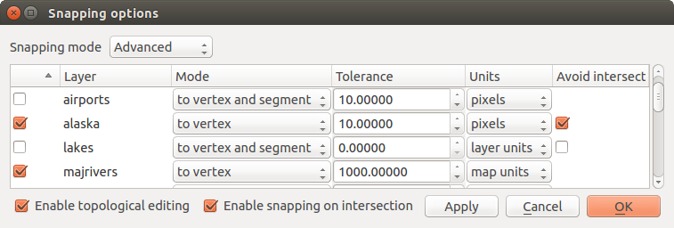
스냅 옵션을 레이어 기반으로 편집 (고급 모드)
참고
스냅을 활성화할 레이어 목록 제어
Snapping Options 대화창의 파라미터들(모드, 허용 오차, 단위)은 기본적으로 Digitizing 탭의 전체 수준 설정으로 맞춰져 있습니다. 고급 모드에서 레이어가 기본적으로 체크되는 – 따라서 스냅이 활성화되는 – 상황을 피하려면, Default Snap mode 를 Off 로 설정하십시오.
스냅 허용 오차를 pixels 또는 map units (맵 뷰의 단위)로 설정할 수 있습니다. 고급 레이어 선택 모드인 상태에서 ‘실시간’ 좌표계 변환이 활성화된 경우, 재투영된 레이어의 단위인 layer units 를 참조하는 스냅 허용 오차를 사용할 수 있습니다.
검색 반경
Search radius is the distance QGIS uses to search for the closest vertex
you are trying to select when you click on the map. If you aren’t within the
search radius, QGIS won’t find and select any vertex for editing.
The search radius for vertex edits can be defined under Settings ‣
Options ‣ Digitizing tab. This is the same
place where you define the general, project-wide snapping tolerance.
Snap tolerance and search radius are set in map units or pixels, so you may find you need to experiment to get them set right. If you specify too big of a tolerance, QGIS may snap to the wrong vertex, especially if you are dealing with a large number of vertices in close proximity. Set search radius too small, and it won’t find anything to move.
위상 편집
Settings (또는 File) 메뉴의 Snapping options... 대화창에서 레이어 기반 스냅 옵션 외에도, 위상 기능들을 정의할 수 있습니다. 이 대화창에서  Enable topological editing 을 선택해서 위상 편집을 활성화할 수 있으며, 그리고/또는 폴리곤 레이어의 경우 Avoid Intersections 옵션을 활성화할 수 있습니다.
위상 편집 활성화하기
Enable topological editing 은 피처 모자이크에서 공통 경계를 편집하고 유지하기 위한 옵션입니다. QGIS는 피처들이 공유하는 경계를 ‘탐지’합니다. 따라서 공통 꼭짓점/선분을 한 번만 이동시켜도, QGIS가 인접 피처 업데이트 작업을 처리할 것입니다.
새 폴리곤의 교차를 피하기
두 번째 위상 옵션 Avoid intersections 는 기존 피처에 중첩하는 새 피처를 그리지 못 하도록 막습니다. 서로 인접한 폴리곤들을 더 빨리 디지타이즈할 수 있도록 해줍니다. 이미 폴리곤이 하나 있는 경우, 이 옵션을 활성화한 상태로 두 번째 폴리곤을 기존 폴리곤과 서로 교차하도록 디지타이즈할 수 있는데, 이때 QGIS는 두 번째 폴리곤을 기존 폴리곤의 경계선으로 자릅니다. 공통 경계선의 꼭짓점을 모두 디지타이즈하지 않아도 된다는 장점이 있습니다.
주석
기존 도형이 새 도형을 완전히 덮는다면, 제공자가 지원하는 경우 새 도형은 제거되며 새 도형 없는 피처가 남을 것입니다. 지원하지 않는 경우 수정 사항을 저장하려 할 때 QGIS가 오류 메시지를 띄울 것입니다.
경고
Avoid Intersections 옵션을 조심해서 사용해야 합니다
이 옵션은 모든 폴리곤 레이어에서 중첩하는 모든 피처의 도형을 자르거나 제거하기 때문에, 더 이상 필요하지 않게 되자마자 이 옵션을 반드시 체크 해제해야 합니다. 그렇지 않을 경우 기대하지 않은 도형을 얻게 될 수 있습니다.
교차점에 스냅 활성화하기
또다른 옵션은 Enable snapping on intersection 을 선택하는 것입니다. 이 옵션은 배경 레이어의 교차점에 – 설령 교차점에 꼭짓점이 없는 경우라도 – 스냅할 수 있게 해줍니다.
도형 확인기
이 핵심 플러그인으로 도형의 유효성을 확인할 수 있습니다. 도형 검증기 플러그인 에서 이 플러그인에 관한 자세한 정보를 찾아볼 수 있습니다.
기존 레이어 디지타이즈 작업
기본적으로, QGIS는 레이어를 읽기 전용으로 불러옵니다. 이 습성은 혹시라도 마우스가 미끄러져 레이어를 실수로 편집하는 일을 피하기 위한 예방책입니다. 하지만, 편집을 지원하는 데이터 제공자이며 (데이터 포맷 및 필드 탐구 참조) 기저 데이터소스가 쓰기 가능인 경우 (예: 파일이 읽기 전용이 아닌 경우) 모든 레이어를 편집할 수 있습니다.
참고
프로젝트 내부에서 레이어 편집 권한 제한
From the Project ‣ Project properties ‣ Identify tab, You can choose to set any layer read-only regardless the provider permission. This can be a handy way, in a multi-users environment to avoid unauthorized users to mistakenly edit layers (e.g., shapefile), hence potentially corrupt data. Note that this setting only applies inside the current project.
일반적으로, 벡터 레이어를 편집하기 위한 도구는 고급 디지타이즈 작업 절에서 설명하는 대로 디지타이즈 작업과 고급 디지타이즈 작업 툴바로 나뉘어져 있습니다. View ‣ Toolbars ‣ 메뉴에서 둘 다 선택하고 선택 해제할 수 있습니다. 기본 디지타이즈 작업 도구를 선택하면, 다음 기능들을 수행할 수 있습니다:
아이콘 |
목적 |
아이콘 |
목적 |
|---|---|---|---|
 |
현재 편집 내용 |
 |
편집 켜고끄기 |
 |
피처 추가: 포인트 캡처 |
 |
피처 추가: 라인 캡처 |
 |
피처 추가: 폴리곤 캡처 |
 |
Move Feature |
 |
Add Circular String |  |
Add Circular String By Radius |
 |
Node Tool |  |
선택 항목 삭제 |
 |
피처 잘라내기 |
 |
피처 복사하기 |
 |
피처 붙여넣기 |
 |
레이어 편집 내용 저장 |
표: 편집 작업 - 벡터 레이어 기본 편집 툴바
이 모든 디지타이즈 작업 도구를 쓰는 도중에 도구를 비활성화시키지 않고서도 맵 캔버스에서 확대/축소 및 이동 할 수 있다는 사실을 기억하십시오.
모든 편집 세션은 선택한 레이어의 컨텍스트 메뉴, 속성 테이블 대화창, 디지타이즈 작업 툴바, 또는 Edit 메뉴에 있는 Toggle editing 옵션을 선택해서 시작됩니다.
레이어를 편집 모드로 전환하면, 편집 작업 툴바에 있는 부가 도구 아이콘들이 활성화되며, Settings ‣ Options... ‣ Digitizing 탭에 있는 Show markers only for selected features 옵션을 체크하지 않은 경우 모든 피처의 꼭짓점에 마커가 나타날 것입니다.
참고
정기적으로 저장하세요
Save Layer Edits 아이콘으로 주기적으로 편집 내용을 저장하는 것을 잊지 마십시오. 이 아이콘을 클릭하면 사용자의 데이터소스가 모든 수정 사항을 받아들일 수 있는지도 확인할 것입니다.
피처 추가하기
You can use the Add Feature,
Add Feature or
Add Feature icons on the toolbar to add new feature (point, line and
polygon) into the current layer.
The next buttons Add circular string or
Add circular string by radius allow users to add
line or polygon features with a circular geometry.
To create features with these tools, you first digitize the geometry then enter its attributes. To digitize the geometry, left-click on the map area to create the first point of your new feature.
For linear or curved geometries, keep on left-clicking for each additional point you wish to capture or use automatic tracing capability to accelerate the digitization. You can switch back and forth between linear Add feature tool and curved Add circular string... tools to create compound curved geometry. Pressing Delete or Backspace key reverts the last node you add. When you have finished adding points, right-click anywhere on the map area to confirm you have finished entering the geometry of that feature.
주석
만곡 도형은 호환되는 데이터 제공자에서만 만곡 도형으로 저장됩니다
Although QGIS allows to digitize curved geometries within any editable data format, you need to be using a data provider (e.g. PostGIS, GML or WFS) that supports curves to have features stored as curved, otherwise QGIS segmentizes the circular arcs. The memory layer provider also supports curves.
참고
디지타이즈 작업 고무줄을 사용자 지정하기
폴리곤을 캡처하는 도중에 기본값인 빨강색 고무줄이 아래에 있는 – 사용자가 포인트를 캡처하고자 하는 – 피처 또는 장소를 가릴 수가 있습니다. Settings ‣ Options ‣ Digitizing 대화창에서 고무줄의 Fill Color 에 대한 투명도(또는 알파 채널)를 높이면 이 문제를 해결할 수 있습니다. 또는 Don’t update rubber band during node editing 옵션을 체크해서 고무줄을 사용하지 않을 수도 있습니다.
디지타이즈 작업을 완료하면 새 피처를 위한 정보를 입력할 수 있는 속성 대화창이 열립니다. 새 벡터 피처를 디지타이즈한 후의 속성 입력 양식 대화창 그림은 알래스카에 있는 가상의 새 강을 위한 속성을 설정하는 예시입니다. 하지만, Settings ‣ Options 메뉴의 Digitizing 대화창에서 다음 옵션들을 활성화시킬 수도 있습니다:
- Suppress attributes pop-up windows after each created
feature to avoid the form opening
- Reuse last entered attribute values: 속성 입력 양식 대화창이 열릴 때 가장 최근에 입력한 속성값으로 자동 입력해서 변경할 값만 입력하면 되도록 합니다.
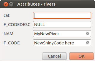
새 벡터 피처를 디지타이즈한 후의 속성 입력 양식 대화창
With the Move Feature(s) icon on the toolbar, you can
move existing features.
Node Tool
For shapefile-based or MapInfo layers as well as SpatiaLite, PostgreSQL/PostGIS,
MSSQL Spatial, and Oracle Spatial tables, the
Node Tool provides manipulation capabilities of
feature vertices similar to CAD programs. It is possible to simply select
multiple vertices at once and to move, add or delete them altogether.
The node tool also works with ‘on the fly’ projection turned on and supports
the topological editing feature. This tool is, unlike other tools in
QGIS, persistent, so when some operation is done, selection stays
active for this feature and tool.
Settings ‣ Options ‣ Digitizing ‣ Search Radius:  검색 반경 속성을 0보다 큰 숫자로 설정하는 것이 중요합니다. 그러지 않을 경우, QGIS가 현재 어떤 꼭짓점을 편집 중인지 구분하지 못 하고 경고 메시지를 표시할 것입니다.
참고
꼭짓점 마커
QGIS 이번 버전은 ‘Semi-transparent circle’, ‘Cross’ 및 ‘None’ 세 종류의 꼭짓점 마커를 지원하고 있습니다. 마커 스타일을 변경하려면, Settings 메뉴에서 Options 를 선택한 다음, Digitizing 탭에서 적절한 항목을 선택하십시오.
기본 작업
Start by activating the Node Tool and selecting a
feature by clicking on it. Red boxes will appear at each vertex of this feature.
- Selecting vertices: You can select vertices by clicking on them one at a time, by clicking on an edge to select the vertices at both ends, or by clicking and dragging a rectangle around some vertices. When a vertex is selected, its color changes to blue. To add more vertices to the current selection, hold down the Ctrl key while clicking. Hold down Ctrl when clicking to toggle the selection state of vertices (vertices that are currently unselected will be selected as usual, but also vertices that are already selected will become unselected).
- Adding vertices: To add a vertex, simply double click near an edge and a new vertex will appear on the edge near to the cursor. Note that the vertex will appear on the edge, not at the cursor position; therefore, it should be moved if necessary.
꼭짓점 삭제하기: 꼭짓점을 선택한 다음 Delete 키를 누르십시오. 피처의 모든 꼭짓점을 삭제하면 – 데이터소스가 지원하는 경우 – 도형이 없는 피처를 생성합니다. 피처를 완전히 삭제하는 것이 아니라 도형만 삭제한다는 점을 기억하십시오. 피처를 완전히 삭제하려면
Delete Selected 도구를 사용해야 합니다.- Moving vertices: Select all the vertices you want to move, click on a selected vertex or edge and drag in the direction you wish to move. All the selected vertices will move together. If snapping is enabled, the whole selection can jump to the nearest vertex or line.
Each change made with the node tool is stored as a separate entry in the Undo dialog. Remember that all operations support topological editing when this is turned on. On-the-fly projection is also supported, and the node tool provides tooltips to identify a vertex by hovering the pointer over it.
참고
Move features with precision
The Move Feature tool doesn’t currently allow to
snap features while moving. Using the Node Tool, select ALL
the vertices of the feature, click a vertex, drag and snap it to a target vertex:
the whole feature is moved and snapped to the other feature.
The Vertex Editor
With activating the Node Tool on a feature, QGIS opens the Vertex Editor panel listing all the vertices of the feature with their x, y (z, m if applicable) coordinates and r (for the radius, in case of circular geometry). Simply select a row in the table does select the corresponding vertex in the map canvas, and vice versa. Simply change a coordinate in the table and your vertex position is updated. You can also select multiple rows and delete them altogether.
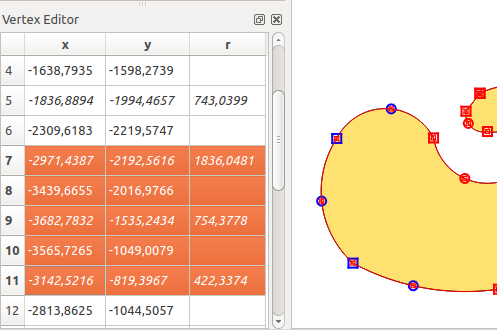
선택한 노드를 보여주는 꼭짓점 편집기 패널
피처 잘라내기, 복사 및 붙여넣기
먼저 Toggle editing 을 통해 대상 레이어를 편집 모드로 설정해놓았다면, 동일한 QGIS 프로젝트의 레이어들 사이에서 선택한 피처를 자르고, 복사하고 붙여넣을 수 있습니다.
참고
복사/붙여넣기를 이용해서 폴리곤을 라인으로, 라인을 폴리곤으로 변형하기
라인 피처를 복사해서 폴리곤 레이어에 붙여넣는 경우, QGIS가 대상 레이어에 그 경계가 라인 피처의 닫힌 도형에 대응하는 폴리곤으로 붙여넣습니다. 이는 동일한 데이터를 가진 서로 다른 도형 유형을 빠르게 생성하는 방법입니다.
외부 응용 프로그램에 피처를 텍스트로 붙여넣을 수도 있습니다. 피처가 도형 데이터를 OGC WKT(Well-Known Text) 서식으로 표현한 CSV 포맷인 경우에 말이죠. QGIS 외부의 WKT 및 GeoJSON 객체를 QGIS 내부의 레이어로 붙여넣는 것도 가능합니다.
복사/붙여넣기 기능이 유용한 경우란 어떤 경우일까요? 바로 한 번에 하나 이상의 레이어를 편집하는 중에 레이어들 간에 피처를 복사/붙여넣기하는 경우입니다. 어째서 이런 작업이 필요한 걸까요? QGIS 예시 데이터의 big_lakes 레이어에 있는 호수 5,000개 전부가 아니라 한두 개만 있는 레이어에서 몇몇 작업을 해야 한다고 가정해봅시다. 새 레이어를 생성한 다음 해당 레이어에 필요한 호수만 복사/붙여넣기를 이용해서 넣을 수 있습니다.
새 레이어에 몇몇 호수를 복사해 넣는 다음 예제를 해보겠습니다:
복사해오려는 레이어(원본 레이어)를 불러옵니다.
복사해 넣으려는 레이어(대상 레이어)를 불러오거나 생성합니다.
대상 레이어를 편집 모드로 설정합니다.
범례에서 원본 레이어를 클릭해서 활성화시킵니다.
 Select Features by area or single click 도구를 이용해서 원본 레이어에서 피처(들)을 선택합니다.
- Copy Features 도구를 클릭합니다.
범례에서 대상 레이어를 클릭해서 활성화시킵니다.
- Paste Features 도구를 클릭합니다.
편집 모드를 해제하고 변경 사항을 저장합니다.
원본과 대상 레이어가 서로 다른 스키마를 가지고 있다면 (필드명과 유형이 동일하지 않다면) 어떻게 될까요? QGIS는 일치하는 데이터를 붙여넣고 나머지는 무시합니다. 대상 레이어에 속성을 복사해 넣을 필요가 없는 경우, 필드 및 데이터 유형을 어떻게 구성하든 상관없습니다. 하지만 전체를 – 피처와 그 속성까지 – 복사하고자 하는 경우, 원본과 대상 레이어의 스키마가 일치하는지 확인해야 합니다.
주석
붙여넣은 피처의 합치성
원본과 대상 레이어가 동일한 투영체를 사용하고 있는 경우, 붙여넣은 피처가 원본 레이어와 동일한 도형을 가지게 될 것입니다. 하지만, 대상 레이어의 투영체가 다른 경우, QGIS는 도형이 동일한지 보장할 수 없게 됩니다. 왜냐하면 서로 다른 투영체 간에 변환할 때 자잘한 반올림 오류가 발생하기 때문입니다.
참고
문자열 속성을 또다른 속성으로 복사하기
사용자의 속성 테이블에 문자열 유형의 새 열을 생성했는데, 더 긴 길이를 가진 다른 속성 열로 그 값을 붙여넣으려는 경우, 열의 길이가 대상 열의 길이로 늘어날 것입니다. GDAL/OGR 1.10과 함께 구동되는 GDAL shapefile 드라이버가 삽입될 데이터의 길이를 동적으로 수용하기 위해 문자열 및 정수형 필드를 자동 확장하기 때문입니다.
선택한 피처 삭제하기
어떤 피처 전체(속성 및 도형)를 삭제하려는 경우, 먼저 표준적인 Select Features by area or single click 도구를 사용해서 도형을 선택할 수 있습니다. 속성 테이블에서 선택할 수도 있습니다. 선택을 마치고 나면, Delete 또는 Backspace 키를 누르거나 Delete Selected 도구를 클릭해서 피처를 삭제하십시오. 선택한 피처 여러 개를 한 번에 삭제할 수 있습니다.
피처를 삭제하는 데 디지타이즈 작업 툴바에 있는 Cut Features 도구를 이용할 수도 있습니다. 이 도구는 피처를 사실상 삭제하지만 “공간 클립보드”에 옮겨 놓기도 합니다. 즉, 삭제할 피처를 잘라내는 겁니다. 이후에 Paste Features 도구를 통해 되돌려 놓을 수 있습니다. 기초 수준의 실행 취소 능력이죠. 잘라내기, 복사 및 붙여넣기는 현재 선택한 피처를 대상으로 작동합니다. 즉 한 번에 하나 이상을 대상으로 작업할 수 있다는 뜻입니다.
편집한 레이어 저장하기
레이어가 편집 모드 상태인 경우, 모든 변경 사항이 QGIS의 메모리에 남아 있습니다. 즉 변경 사항이 즉시 데이터소스 또는 디스크에 커밋 또는 저장되는 것이 아닙니다. 현재 레이어에 편집 사항을 저장하고 싶지만 편집 모드를 해제하지 않고 계속 편집 작업을 하고 싶은 경우, Save Layer Edits 아이콘을 클릭하면 됩니다. Toggle editing 아이콘으로 편집 모드를 끄는 경우 (또는 QGIS를 종료하는 경우) 사용자의 변경 사항을 저장할 거냐 또는 무시할 거냐를 묻는 대화창이 열립니다.
변경 사항을 저장할 수 없는 경우 (예: 디스크에 남은 공간이 없거나, 범위를 벗어난 속성값이 있는 경우) QGIS의 내부 메모리 상태가 보존됩니다. 사용자가 편집 사항을 조정해서 다시 저장할 수 있게 하기 위해서입니다.
참고
데이터 무결성
편집 작업을 시작하기 전에 항상 사용자 데이터소스를 백업하도록 권장합니다. QGIS 개발자들이 사용자 데이터의 무결성을 보존하기 위해 모든 노력을 다 하고 있지만, 어떤 보장도 해드릴 수 없기 때문입니다.
여러 레이어를 한 번에 저장하기
이 기능은 여러 레이어를 디지타이즈할 수 있게 해줍니다. 사용자가 여러 레이어에서 만든 모든 변경 사항을 저장하려면  Save for Selected Layers 를 선택하십시오.
  Rollback for Selected Layers 를 클릭하면, 선택한 모든 레이어에 대한 디지타이즈 작업을 되돌릴 수도 있습니다. 선택한 레이어에 대한 편집 작업을 종료하려면,
  Cancel for Selected Layer(s) 를 통해 쉽게 끝낼 수 있습니다.
프로젝트의 모든 레이어 편집 작업에서 동일한 기능들을 사용할 수 있습니다.
참고
여러 레이어 변경 사항을 한 번에 편집, 저장 또는 되돌리는 데 트랜잭션 그룹 이용하기
When working with layers from the same PostGreSQL database, activate the Automatically create transaction groups where possible option in Project ‣ Project Properties ‣ Data Sources to sync their behavior (enter or exit the edit mode, save or rollback changes at the same time).
고급 디지타이즈 작업
아이콘 |
목적 |
아이콘 |
목적 |
|---|---|---|---|
 |
고급 디지타이즈 작업 도구 활성화 |
 |
투사 활성화 |
 |
실행 취소 |
 |
재실행 |
 |
피처(들) 기울이기 |
 |
피처 단순화 |
 |
고리 추가 |
 |
부분 추가 |
 |
고리 채우기 |
||
 |
고리 삭제 |
 |
부분 삭제 |
 |
오프셋 곡선 |
 |
피처 재형성 |
 |
부분 분할 |
 |
피처 분할 |
 |
선택한 피처의 속성 병합 |
 |
선택한 피처 병합 |
 |
포인트 심볼 기울이기 |
 |
오프셋 포인트 심볼 |
표: 고급 편집 작업 - 벡터 레이어 고급 편집 작업 툴바
실행 취소 및 재실행
Undo 및 Redo 도구는 벡터 편집 작업을 실행 취소하거나 재실행할 수 있습니다. 실행 취소/재실행 이력에 있는 모든 작업을 보여주는 고정 가능한(dockable) 위젯도 있습니다. (실행 취소/재실행 디지타이즈 작업 이력 그림을 참조하세요.) 이 위젯은 기본적으로 표시되지 않습니다. 이 위젯을 표시하려면 툴바를 오른쪽 클릭한 다음 Undo/Redo Panel 을 활성화해야 합니다. 하지만 이 위젯이 표시되지 않은 경우에도 실행 취소/재실행 능력은 켜져 있습니다.
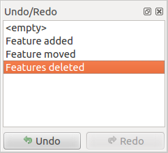
실행 취소/재실행 디지타이즈 작업 이력
[Undo] 버튼을 클릭하거나 Ctrl+Z (또는  Cmd+Z) 조합키를 누르면, 모든 피처와 속성의 상태가 되돌린 작업 이전의 상태로 돌아갑니다. 일반적인 벡터 편집 작업이 아닌 변경 사항(예: 플러그인을 통한 변경 사항)은 해당 변경 사항이 어떻게 수행됐는지에 따라 되돌릴 수도 있고 되돌리지 못 할 수도 있습니다.
실행 취소/재실행 이력 위젯을 이용하려면, 그냥 이력 목록에 있는 작업을 하나 선택하십시오. 모든 피처가 선택한 작업 직후의 상태로 돌아갈 것입니다.
피처(들) 기울이기
Use Rotate Feature(s) to rotate one or multiple features
in the map canvas. Press the Rotate Feature(s) icon and then
click on the feature to rotate. Either click on the map to place the rotated feature or
enter an angle in the user input widget. If you want to rotate several features,
they shall be selected first.
If you enable the map tool with feature(s) selected, its (their) centroid appears and will be the rotation anchor point. If you want to move the anchor point, hold the Ctrl button and click on the map to place it.
맵을 클릭하기 전에 Shift 키를 누른 상태인 경우, 45도씩 기울어질 것입니다. 이후 사용자 입력 위젯에서 각도를 수정할 수 있습니다.
To abort feature rotation, you need to click on Rotate
Feature(s) icon.
피처 단순화
The Simplify Feature tool allows you to reduce the
number of vertices of a feature, as long as the geometry remains valid. With the
tool you can also simplify many features at once or multi-part features.
First, click on the feature or drag a rectangle over the features. A dialog where you can define a tolerance in map units, layer units or pixels pops up and a colored and simplified copy of the feature(s), using the given tolerance, appears over them. QGIS calculates the amount of vertices that can be deleted while maintaining the geometry. The higher the tolerance is the more vertices can be deleted. When the expected geometry fits your needs just click the [OK] button. The tolerance you used will be saved when leaving a project or when leaving an edit session. So you can go back to the same tolerance the next time when simplifying a feature.
To abort feature simplification, you need to click on
Simplify Feature icon.
주석
렌더링만을 위해 도형을 단순화하는 Settings ‣ Options ‣ Rendering 메뉴의 피처 단순화 옵션과는 달리, Simplify Feature 도구는 데이터소스에 있는 피처의 도형을 영구히 변경합니다.
부분 추가
Add Part 도구로 선택한 피처에 부분을 추가해서 멀티포인트, 멀티라인 또는 멀티폴리곤 피처를 생성할 수 있습니다. 기존 피처 외부에서 이 새 부분을 디지타이즈해야만 하는데, 이 기존 피처는 먼저 선택돼 있어야 합니다.
도형이 없는 피처에 도형을 추가하는 경우에도 Add Part 도구를 사용할 수 있습니다. 먼저, 속성 테이블에서 피처를 선택한 다음 Add Part 도구로 새 도형을 디지타이즈하십시오.
부분 삭제
Delete Part 도구는 다중 피처에서 부분을 삭제할 수 있습니다. (예를 들면 멀티폴리곤 피처에서 폴리곤을 삭제할 수 있습니다.) 이 도구는 포인트, 라인 및 폴리곤 모든 다중 부분 도형에 대해 작동합니다. 더우기, 피처의 도형 요소를 완전히 제거할 수도 있습니다. 부분을 삭제하려면, 그냥 대상 피처 안에 있는 부분을 클릭하면 됩니다.
고리 추가
툴바에 있는 Add Ring 아이콘을 클릭하면 고리 폴리곤을 생성할 수 있습니다. 기존 폴리곤 영역 내부에 ‘구멍’으로 간주되는 내곽 폴리곤을 디지타이즈할 수 있다는 뜻으로, 이 경우 외곽 및 내곽 폴리곤 경계선 사이의 영역만 고리 폴리곤으로 남게 됩니다.
고리 채우기
You can use the Fill Ring function to add a ring to
a polygon and add a new feature to the layer at the same time. Using this tool,
you simply have to digitize a polygon within an existing one. Thus you need not
first use the Add Ring icon and then the
Add feature function anymore.
고리 삭제
Delete Ring 도구는 구멍 안쪽을 클릭해서 기존 폴리곤 내부의 고리를 삭제할 수 있습니다. 이 도구는 폴리곤 및 멀티폴리곤 피처에 대해서만 작동합니다. 폴리곤의 외곽 고리에 이 도구를 사용해도 아무것도 변경되지 않습니다.
피처 재형성
툴바에 있는 Reshape Features 도구를 사용해서 라인 및 폴리곤 피처를 재형성할 수 있습니다. 라인의 경우, 원본 라인을 첫 번째 교차점에서 마지막 교차점까지의 라인 부분으로 대체합니다.
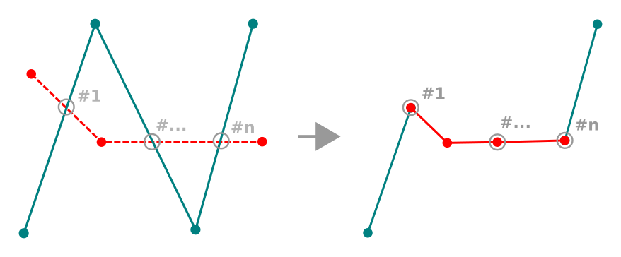
라인 재형성하기
참고
재형성 도구로 라인스트링 도형을 연장시키기
Reshape Features 도구를 이용해서 기존 라인의 첫 번째 또는 마지막 꼭짓점에 스냅한 다음 새 라인을 그리면 기존 라인스트링 도형을 늘릴 수 있습니다. 새 라인을 승인하면 피처 도형이 두 라인의 결합체로 변합니다.
폴리곤의 경우, 이 도구는 폴리곤의 경계선을 재형성합니다. 제대로 동작하려면, 재형성 도구의 라인이 폴리곤 경계선과 최소한 두 번 교차해야만 합니다. 라인을 그리려면, 맵 캔버스를 클릭해서 꼭짓점을 추가하십시오. 그리기를 마치려면, 오른쪽 클릭만 하면 됩니다. 라인의 경우와 마찬가지로, 첫 번째와 마지막 교차점 사이에 있는 선분만 처리됩니다. 폴리곤 내부에 있는 재형성 라인의 선분은 폴리곤을 잘라내고, 외부에 있는 선분은 폴리곤을 확장시킬 것입니다.
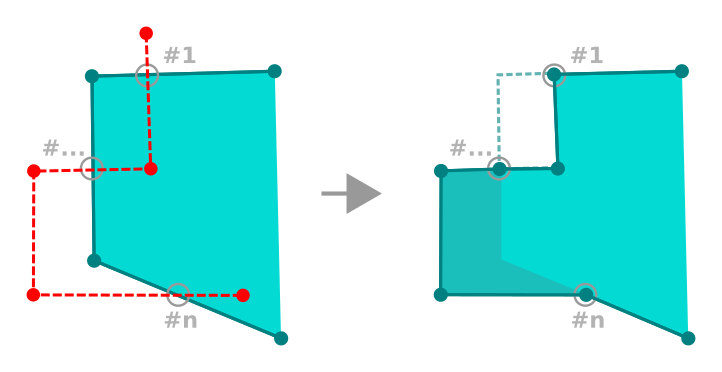
폴리곤 재형성하기
폴리곤의 경우, 재형성 작업이 때로 의도하지 않은 결과를 낼 수도 있습니다. 이 도구는 폴리곤의 자잘한 부분을 수정하는 데 유용하지, 본체를 수정하기는 힘듭니다. 또 재형성 라인이 여러 폴리곤 고리와 교차해서도 안 됩니다. 그런 경우 유효하지 않은 폴리곤이 생성되기 때문입니다.
주석
재형성 도구는 폴리곤 고리 또는 닫힌 라인의 시작점을 변경시킬 수도 있습니다. 즉, ‘두 번’ 나타나던 포인트가 더 이상 그러지 않을 수도 있다는 뜻입니다. 대부분의 응용 프로그램에서 문제가 없을 수도 있지만, 고려해야 할 사항임에는 틀림없습니다.
오프셋 곡선
Offset Curve 도구는 라인 레이어를 평행하게 이동시킨 객체를 생성합니다. 이 도구를 편집 중인 레이어에 적용하면 도형을 수정하며, 배경 레이어에 적용하면 라인/고리를 복사해서 편집 중인 레이어에 추가합니다. 따라서 이 도구는 거리 라인 레이어를 생성하는 데 적합합니다. 이 도구는 변위 거리를 보여주는 User Input 대화창을 엽니다.
라인 레이어를 이동시킨 객체를 생성하려면, 먼저 편집 모드를 켠 다음 Offset Curve 도구를 활성화시켜야 합니다. 그 다음 피처를 클릭해서 이동시킵니다. 마우스를 움직여 원하는 곳을 클릭하거나 또는 사용자 입력 위젯에 원하는 거리를 입력하십시오. 이동 후에 Save Layer Edits 도구로 사용자 변경 사항을 저장할 수도 있습니다.
QGIS 옵션 대화창(의 디지타이즈 탭에서 Curve offset tools 부분)에서 Join style, Quadrant segments, Miter limit 과 같은 몇몇 파라미터를 환경 설정할 수 있습니다.
피처 분할
You can split features using the Split Features
icon on the toolbar. Just draw a line across the feature you want to split.
부분 분할
QGIS는 다중 부분 피처의 부분을 분할해서 부분의 개수를 늘릴 수 있습니다. Split Parts 도구를 사용해서 분할하고 싶은 부분을 가로지르는 라인을 그리기만 하면 됩니다.
참고
Split a polyline feature in one-click
A single click on a snapped vertex of a line feature with the
Split Features or Split Parts tool is enough to have it
split into new features or parts.
선택한 피처 병합
Merge Selected Features 도구는 기존 피처들을 합쳐서 새 피처를 생성할 수 있습니다. 기존 피처의 도형들을 병합해서 새 피처를 생성합니다. 기존 피처들에 공통 경계가 없는 경우, 멀티폴리곤/멀티폴리라인/멀티포인트 피처를 생성합니다.
First, select several features. Then press the Merge Selected
Features button. In the new dialog, you can select at the top of the dialog which value to
apply to each field of the new feature. That value can be:
- picked from the attributes of the initial features,
- an aggregation of the initial features attributes (Minimum, Maximum, Median, Sum, Count Concatenation... depending on the type of the field. see 통계 요약 패널 for the full list of functions),
- skipped, meaning that the field will be empty,
- or manually entered, at the bottom of the rows.
선택한 피처의 속성 병합
Merge Attributes of Selected Features 도구는 피처들의 경계를 병합하지 않고서도 피처에 동일한 속성을 적용할 수 있게 해줍니다. 이 도구의 대화창은 Merge Selected Features 도구의 대화창과 동일합니다. 다만 선택한 개체들의 속성은 동일하게 변하지만, 개체 도형은 그대로 유지된다는 점이 다릅니다.
포인트 심볼 기울이기
The Rotate Point Symbols allows you to change the rotation
of point symbols in the map canvas. First of all, you must apply to the symbol a
data-defined rotation: in the Layer Properties
‣ Style dialog, click the  Data-defined override widget
near the Rotation option of the highest level (preferably) of the symbol
layers and choose a field in the Field Type combobox. Values of this
field are hence used to rotate each feature’s symbol accordingly.
Data-defined override widget
near the Rotation option of the highest level (preferably) of the symbol
layers and choose a field in the Field Type combobox. Values of this
field are hence used to rotate each feature’s symbol accordingly.
주석
As a global option, setting the rotation field at the first level of the symbol applies it to all the underlying levels while setting it at a lower level will rotate only this symbol layer (unless you have a single symbol layer).
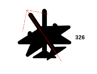
포인트 심볼 기울이기
To change the rotation of a symbol, click on a point feature in the map canvas
with the Rotate Point Symbols and move the mouse around,
holding the left button pressed. A red arrow with the rotation value
will be visualized (see Figure_rotate_point). When you release the left mouse
button again, the symbol is defined with this new rotation and the rotation
field is updated in the layer’s attribute table.
참고
Ctrl 키를 누르고 있을 경우, 15도씩 기울어질 것입니다.
오프셋 포인트 심볼
Offset Point Symbols 도구는 포인트 심볼이 맵 캔버스에 렌더링된 위치를 대화형으로 변경할 수 있습니다. 이 도구는 Rotate Point Symbols 도구와 비슷하게 동작합니다만, 심볼의 데이터로 정의된 Offset (X,Y) 속성에 연결해야 한다는 점이 다릅니다. 이 오프셋 필드에 연결하면, 포인트 심볼의 좌표가 오프셋 좌표로 변경돼 맵 캔버스에 있는 심볼도 이동합니다.
주석
The Offset Point Symbols tool doesn’t
move the point feature itself; you should use the Node Tool
or Move Feature tool for this purpose.
경고
Ensure to assign the same field to all symbol layers
If at least two layers of the symbol have different fields assigned to their data-defined property (e.g. rotation), the corresponding tool will consider that no field is assigned to the symbol property and won’t perform the action.
자동 투사하기
Usually, when using capturing map tools (add feature, add part, add ring, reshape and split), you need to click each vertex of the feature.
Using the automatic tracing mode you can speed up the digitization process.
Enable the Tracing tool by pushing the icon or pressing
t key and snap to a vertex or segment of a
feature you want to trace along. Move the mouse over another vertex or segment
you’d like to snap and instead of an usual straight line, the digitizing rubber
band represents a path from the last point you snapped to the current position.
QGIS actually uses the underlying features topology to build the shortest path
between the two points. Click and QGIS places the intermediate vertices following
the path. You no longer need to manually place all the vertices during digitization.
Tracing requires snapping to be activated in traceable layers to build the path. You should also snap to an existing vertex or segment while digitizing and ensure that the two nodes are topologically connectable following existing features, otherwise QGIS is unable to connect them and thus traces a single straight line.
주석
최적의 투사를 위해 맵 축척 또는 스냅 설정을 조정하기
맵 캔버스에 너무 많은 피처들이 있는 경우, 잠재적으로 너무 긴 투사 구조 준비 및 대용량 메모리 부담을 피하기 위해 투사를 비활성화시킵니다. 맵을 확대하거나 일부 레이어를 비활성화하면 다시 투사를 활성화시킵니다.
참고
Quickly enable or disable automatic tracing by pressing t key
By pressing t key, tracing can be enabled/disabled anytime even while digitizing one feature, so it is possible to digitize some parts of the feature with tracing enabled and other parts with tracing disabled. Tools behave as usual when tracing is disabled.
고급 디지타이즈 작업 패널
새로운 또는 기존 도형을 캡처, 재형성, 분할하는 경우 고급 디지타이즈 작업 패널을 이용할 수도 있습니다. 라인을 정확히 평행으로 또는 특정 각도에 직각으로 디지타이즈할 수도 있고, 라인을 지정 각도로 고정시킬 수도 있습니다. 게다가, 좌표를 직접 입력해서 사용자의 새 도형을 정밀하게 정의할 수도 있습니다.
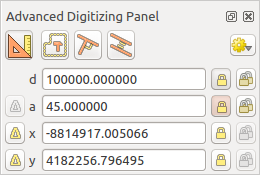
고급 디지타이즈 작업 패널
주석
맵 뷰가 지리 좌표인 경우 이 도구들을 활성화할 수 없습니다.
The Advanced Digitizing panel can be open either with a right-click on the
toolbar and choose Advanced Digitizing panel or in View ‣
Panels ‣ Advanced Digitizing Panel. Once the panel is visible, click the
enable advanced digitizing tool button to activate the Advanced
Digitizing tool.
개념
고급 다지타이즈 작업 도구의 목적은 맵 캔버스에서 디지타이즈 작업 도중 마우스를 이동시킬 때 좌표, 길이 그리고 각도를 고정하는 것입니다.
또한 상대 또는 절대 참조로 제약 조건을 생성할 수도 있습니다. 상대 참조란 이전 꼭짓점 또는 선분에 따라 다음 꼭짓점 제약 조건의 값이 변한다는 뜻입니다.
스냅 설정
고급 디지타이즈 작업 도구의 스냅 환경을 설정하려면  아이콘을 클릭하십시오. 이 도구가 공통 각도로 스냅하도록 할 수 있습니다. 옵션은 다음과 같습니다:
- Do not snap to common angles
- Snap to 30º angles
- Snap to 45º angles
- Snap to 90º angles
피처에 어떻게 스냅할지도 설정할 수 있습니다. 옵션은 다음과 같습니다:
- Do not snap to vertices or segments
- Snap according to project configuration
- Snap to all layers
키보드 단축키
고급 디지타이즈 작업 패널의 활용 속도를 높이려면, 다음과 같은 키보드 단축키를 사용할 수 있습니다:
키 |
간단한 설명 |
Ctrl + or Alt + | Shift + |
|---|---|---|---|
| d | 거리 설정 |
거리 고정 |
|
| a | 각도 설정 |
각도 고정 |
마지막 선분에 상대적인 각도 켜고끄기 |
| x | Set x coordinate | Lock x coordinate | Toggle relative x to last vertex |
| y | Set y coordinate | Lock y coordinate | Toggle relative y to last vertex |
| c | 작성 모드 켜고끄기 |
||
| p | 수직 및 평행 모드 켜고끄기 |
||
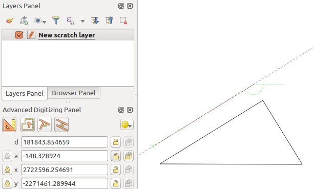
절대 참조 디지타이즈 작업
아무것도 없는 상태에서 새 도형을 그리는 경우, 지정한 좌표에서 꼭짓점 디지타이즈를 시작할 수 있다면 매우 편리합니다.
예를 들면 폴리곤 레이어에 새 피처를 추가하려면, 아이콘을 클릭하십시오. 피처 편집을 시작하길 바라는 X 및 Y 좌표를 다음과 같이 선택할 수 있습니다:
- Click the x text box (or use the x keyboard shortcuts).
원하는 X 좌표를 입력한 다음 Enter 키를 누르거나 오른쪽에 있는
 아이콘을 클릭하면 맵 캔버스 상의 X 좌표의 축에 마우스가 고정됩니다.
- Click the y text box (or use the y keyboard shortcuts).
원하는 Y 좌표를 입력한 다음 Enter 키를 누르거나 오른쪽에 있는
아이콘을 클릭하면 맵 캔버스 상의 Y 좌표의 축에 마우스가 고정됩니다.
파랑색 점선 2개와 초록색 가위표가 사용자가 입력한 좌표를 정확히 가리키고 있습니다. 마우스 위치는 초록색 가위표에 고정돼 있습니다. 맵 캔버스를 클릭해서 디지타이즈 작업을 시작하십시오.
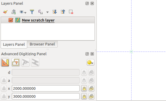
지정 좌표에서 그리기 시작
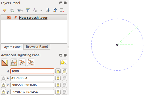
사용자의 손으로 직접 디지타이즈를 계속해서 좌표 몇 쌍을 추가할 수도 있고, 또는 선분의 길이 (거리) 및 각도 를 입력할 수도 있습니다.
If you want to draw a segment of a given length, click the d
(distance) text box (keyboard shortcut d), type the distance value (in
map units) and press Enter or click the button on the right to
lock the mouse in the map canvas to the length of the segment.
In the map canvas, the clicked point is surrounded by a circle whose radius is
the value entered in the distance text box.
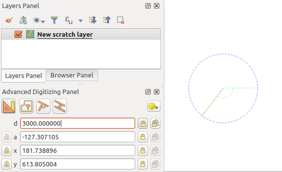
고정 길이 선분
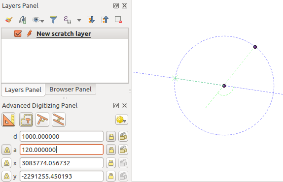
Finally, you can also choose the angle of the segment. As described before ,
click the a (angle) text box (keyboard shortcut a), type the
angle value (in degrees), and press Enter or click the buttons
on the right to lock it. In this way the segment will follow the desired angle:
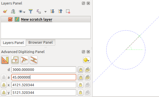
고정 각도 선분
상대 참조 디지타이즈 작업
각도 또는 좌표의 절대값을 사용하는 대신, 직전에 디지타이즈한 꼭짓점 또는 선분에 상대적인 값을 사용할 수도 있습니다.
For angles, you can click the  button on the left of the a
text box (or press Shift + a) to toggle relative angles to the previous
segment. With that option on, angles are measured between the last segment
and the mouse pointer.
button on the left of the a
text box (or press Shift + a) to toggle relative angles to the previous
segment. With that option on, angles are measured between the last segment
and the mouse pointer.
For coordinates, click the buttons to the left of the x or
y text boxes (or press Shift + x or Shift + y) to
toggle relative coordinates to the previous vertex. With these options on,
coordinates measurement will consider the last vertex to be the x and y axes
origin.
지속 고정
Both in absolute or relative reference digitizing, angle, distance, x and y
constraints can be locked continuously by clicking the  Continuous lock buttons. Using continuous lock allows you to
digitize several points or vertexes using the same constraints.
Continuous lock buttons. Using continuous lock allows you to
digitize several points or vertexes using the same constraints.
Parallel and perpendiculars line
앞에서 설명한 모든 도구들은  Perpendicular 및
  Parallel 도구와 결합해서 사용할 수 있습니다. 이 두 도구는 선분을 또다른 선분에 완벽히 직각으로 또는 평행하게 그릴 수 있습니다.
To draw a perpendicular segment, during the editing click the
Perpendicular icon (keyboard shortcut p) to
activate it. Before drawing the perpendicular line,
click on the segment of an existing feature that you want to be perpendicular
to (the line of the existing feature will be colored in light orange); you
should see a blue dotted line where your feature will be snapped:
수직 디지타이즈 작업
To draw a parallel feature, the steps are the same: click on the
Parallel icon (keyboard shortcut p twice), click on
the segment you want to use as reference and start drawing your feature:
평행 디지타이즈 작업
이 두 도구는 수직 및 평행 각도에 딱 맞는 각도를 찾아서 편집 작업 중에 해당 파라미터를 고정시킵니다.
작성 모드
You can enable and disable construction mode by clicking on the
 Construction icon or with the c keyboard
shortcut. While in construction mode, clicking the map canvas won’t add new
vertexes, but will capture the clicks’ positions so that you can use them as
reference points to then lock distance, angle or x and y relative values.
Construction icon or with the c keyboard
shortcut. While in construction mode, clicking the map canvas won’t add new
vertexes, but will capture the clicks’ positions so that you can use them as
reference points to then lock distance, angle or x and y relative values.
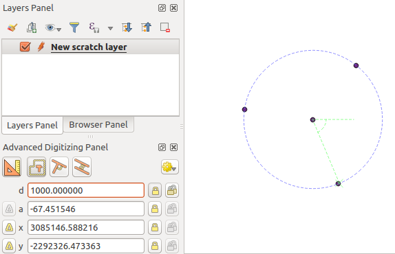
예를 들어, 기존 포인트에서 정확이 동일 거리에 있는 포인트를 몇 개 그리는 데 작성 모드를 사용할 수 있습니다.
With an existing point in the map canvas and the snapping mode correctly
activated, you can easily draw other points at given distances and angles from
it. In addition to the button, you have to activate also the
construction mode by clicking the Construction
icon or with the c keyboard shortcut.
Click next to the point from which you want to calculate the distance and click on the d box (d shortcut) type the desired distance and press Enter to lock the mouse position in the map canvas:
포인트로부터의 거리
Before adding the new point, press c to exit the construction mode. Now, you can click on the map canvas, and the point will be placed at the distance entered.
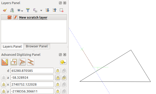
You can also use the angle constraint to, for example, create another point at
the same distance of the original one, but at a particular angle from the newly
added point. Click the Construction icon or with the
c keyboard shortcut to enter construction mode. Click the recently added
point, and then the other one to set a direction segment. Then, click on the
d text box (d shortcut) type the desired distance and press
Enter. Click the a text box (a shortcut) type the
angle you want and press Enter. The mouse position will be locked both in
distance and angle.
포인트들로부터의 거리 및 각도
Before adding the new point, press c to exit the construction mode. Now, you can click on the map canvas, and the point will be placed at the distance and angle entered. Repeating the process, several points can be added.
지정 거리 및 각도에 있는 포인트들