14. Working with Mesh Data
14.1. What’s a mesh?
A mesh is an unstructured grid usually with temporal and other components. The spatial component contains a collection of vertices, edges and/or faces, in 2D or 3D space:
vertices - XY(Z) points (in the layer’s coordinate reference system)
edges - connect pairs of vertices
faces - a face is a set of edges forming a closed shape - typically a triangle or a quadrilateral (quad), rarely polygons with more vertices
Relying on the above, mesh layers can thus have different types of structure:
1D Meshes: consist of vertices and edges. An edge connects two vertices and can have assigned data (scalars or vectors) on it. The 1D mesh network can be for example used for modelling of an urban drainage system.
2D meshes: consist of faces with triangles, regular or unstructured quads.
3D layered meshes: consist of multiple stacked 2D unstructured meshes each extruded in the vertical direction (levels) by means of a vertical coordinate. The vertices and faces have the same topology in each vertical level. The mesh definition (vertical level extrusion) could in general change in time. The data is usually defined in volume centres or by some parametric function.
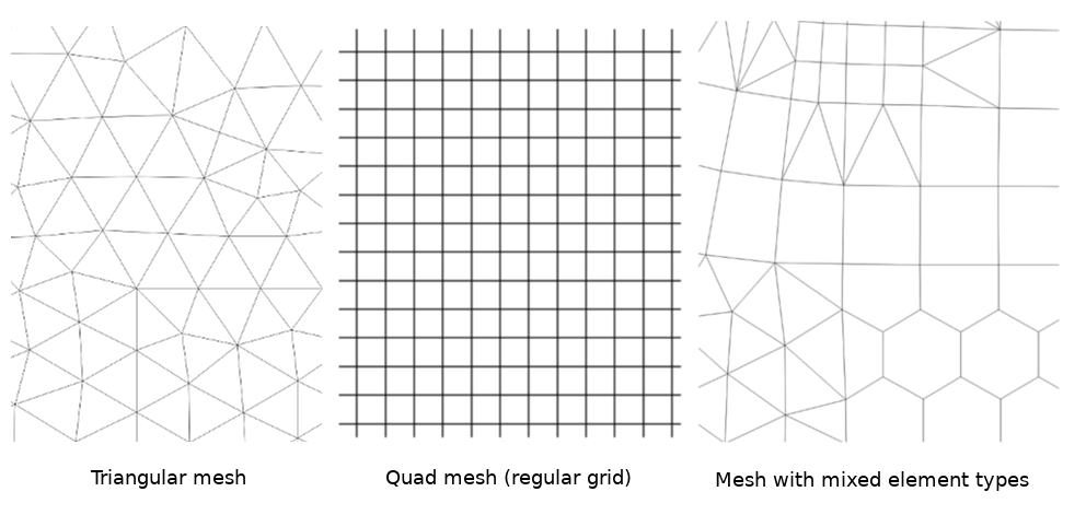
Fig. 14.1 Different mesh types
Mesh provides information about the spatial structure. In addition, the mesh can have datasets (groups) that assign a value to every vertex. For example, having a triangular mesh with numbered vertices as shown in the image below:
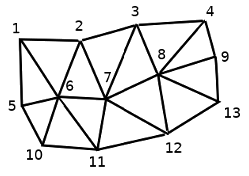
Fig. 14.2 Triangular grid with numbered vertices
Each vertex can store different datasets (typically multiple quantities), and those datasets can also have a temporal dimension. Thus, a single file may contain multiple datasets.
The following table gives an idea about the information that can be stored in mesh datasets. Table columns represent indices of mesh vertices, each row represents one dataset. Datasets can have different datatypes. In this case, it stores wind velocity at 10m at a particular moments in time (t1, t2, t3).
In a similar way, the mesh dataset can also store vector values for each vertex. For example, wind direction vector at the given time stamps:
10 metre wind |
1 |
2 |
3 |
… |
|---|---|---|---|---|
10 metre speed at time=t1 |
17251 |
24918 |
32858 |
… |
10 metre speed at time=t2 |
19168 |
23001 |
36418 |
… |
10 metre speed at time=t3 |
21085 |
30668 |
17251 |
… |
… |
… |
… |
… |
… |
10m wind direction time=t1 |
[20,2] |
[20,3] |
[20,4.5] |
… |
10m wind direction time=t2 |
[21,3] |
[21,4] |
[21,5.5] |
… |
10m wind direction time=t3 |
[22,4] |
[22,5] |
[22,6.5] |
… |
… |
… |
… |
… |
… |
We can visualize the data by assigning colors to values (similarly to how it is done with Singleband pseudocolor raster rendering) and interpolating data between vertices according to the mesh topology. It is common that some quantities are 2D vectors rather than being simple scalar values (e.g. wind direction). For such quantities it is desirable to display arrows indicating the directions.
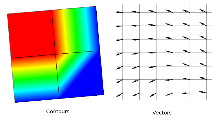
Fig. 14.3 Possible visualisation of mesh data
14.2. Supported formats
QGIS accesses mesh data using the MDAL drivers, and natively supports a variety of formats. Whether QGIS can edit a mesh layer depends on the format and the mesh structure type.
To load a mesh dataset into QGIS, use the  Mesh tab
in the Data Source Manager dialog. Read Loading a mesh layer for
more details.
14.3. Mesh Dataset Properties
The Layer Properties dialog for a mesh layer provides general settings to manage dataset groups of the layer and their rendering (active dataset groups, symbology, 2D and 3D rendering). It also provides information about the layer.
To access the Layer Properties dialog:
In the Layers panel, double-click the layer or right-click and select Properties… from the pop-up menu;
Go to menu when the layer is selected.
The mesh Layer Properties dialog provides the following sections:
Note
Most of the properties of a mesh layer can be saved to or loaded from
a .qml using the Style menu at the bottom of the dialog.
More details at Managing Custom Styles.
14.3.1. Information Properties
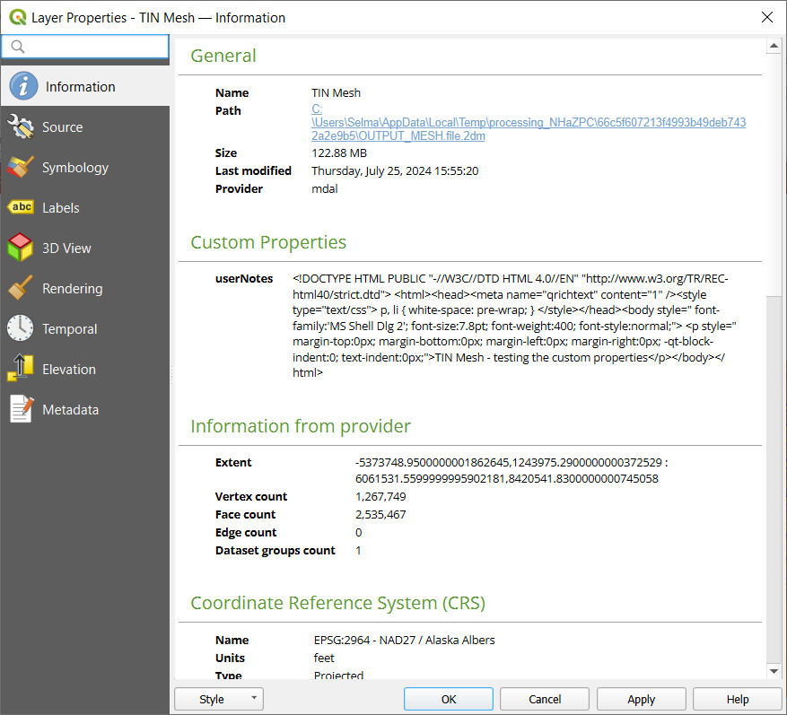
Fig. 14.4 Mesh Layer Information Properties
The  Information tab is read-only and represents an interesting
place to quickly grab summarized information and metadata on the current layer.
Provided information are:
general such as name in the project, source path, list of auxiliary files, last save time and size, the used provider
custom properties, used to store in the active project additional information about the layer. Default custom properties may include layer notes. More properties can be created and managed using PyQGIS, specifically through the setCustomProperty() method.
based on the provider of the layer: extent, vertex, face, edges and/or dataset groups count
the Coordinate Reference System: name, units, method, accuracy, reference (i.e. whether it’s static or dynamic)
extracted from filled metadata: access, extents, links, contacts, history…
14.3.2. Source Properties
The  Source tab displays basic information about
the selected mesh, including:
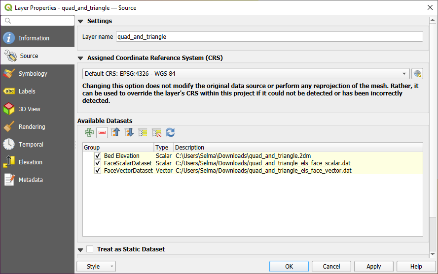
Fig. 14.5 Mesh Layer Source Properties
the layer name to display in the Layers panel
setting the Coordinate Reference System: Displays the layer’s Assigned Coordinate Reference System (CRS). You can change the layer’s CRS by selecting a recently used one in the drop-down list or clicking on
 Select CRS button (see Coordinate Reference System Selector).
Use this process only if the CRS applied to the layer is wrong or
if none was applied.
Select CRS button (see Coordinate Reference System Selector).
Use this process only if the CRS applied to the layer is wrong or
if none was applied.The Available datasets frame lists all the dataset groups (and subgroups) in the mesh layer, with their type and description in a tree view. Both regular datasets (i.e. their data is stored in the file) and virtual datasets (which are calculated on the fly) are listed.
Use the
 Assign Extra Dataset to Mesh button to add more
groups to the current mesh layer. You can add dataset group to a mesh layer with the same name,
but not from the same URI. Dataset group names are automatically renamed to
“Original Name_Number”.
Assign Extra Dataset to Mesh button to add more
groups to the current mesh layer. You can add dataset group to a mesh layer with the same name,
but not from the same URI. Dataset group names are automatically renamed to
“Original Name_Number”.Use
 Remove Extra Dataset from Mesh to remove additional datasets
groups from the mesh layer. Note that only dataset groups not associated with the
mesh source file can be removed.
 Collapse all and
  Expand
all the dataset tree, in case of embedded groups
Expand
all the dataset tree, in case of embedded groupsIf you are interested in few datasets, you can uncheck the others and make them unavailable in the project
Double-click over a name and you can rename the dataset.
 Reset to defaults: checks all the groups and
renames them back to their original name in the provider.
Reset to defaults: checks all the groups and
renames them back to their original name in the provider.Right-click over a virtual dataset group and you can:
Remove dataset group from the project
Save dataset group as… a file on disk, to any supported format. The new file is kept assigned to the current mesh layer in the project.
Checking the
 Treat as static dataset group allows
to ignore the map temporal navigation properties
while rendering the mesh layer.
For each active dataset group (as selected in
 Datasets tab), you can:
set to None: the dataset group is not displayed at all
Display dataset: e.g., for the “bed elevation” dataset which is not time aware
extract a particular date time: the dataset matching the provided time is rendered and stays fixed during map navigation.
14.3.3. Symbology Properties
Click the  Symbology button to activate the dialog.
Symbology properties are divided into several tabs:
14.3.3.1. Datasets
The tab  Datasets is the main place to control and set which
datasets will be used for the layer. It presents the following items:
Groups available in the mesh dataset, with whether they provide:
or
 vector dataset: by default, each vector dataset has
a scalar dataset representing its magnitude automatically generated.
Click on the icon next to the dataset name to select the group and type of data to represent.
Selected dataset group(s) metadata, with details on:
the mesh type: edges or faces
the data type: vertices, edges, faces or volume
whether it’s of vector type or not
the original name in the mesh layer
the unit, if applicable
blending mode available for the selected datasets.
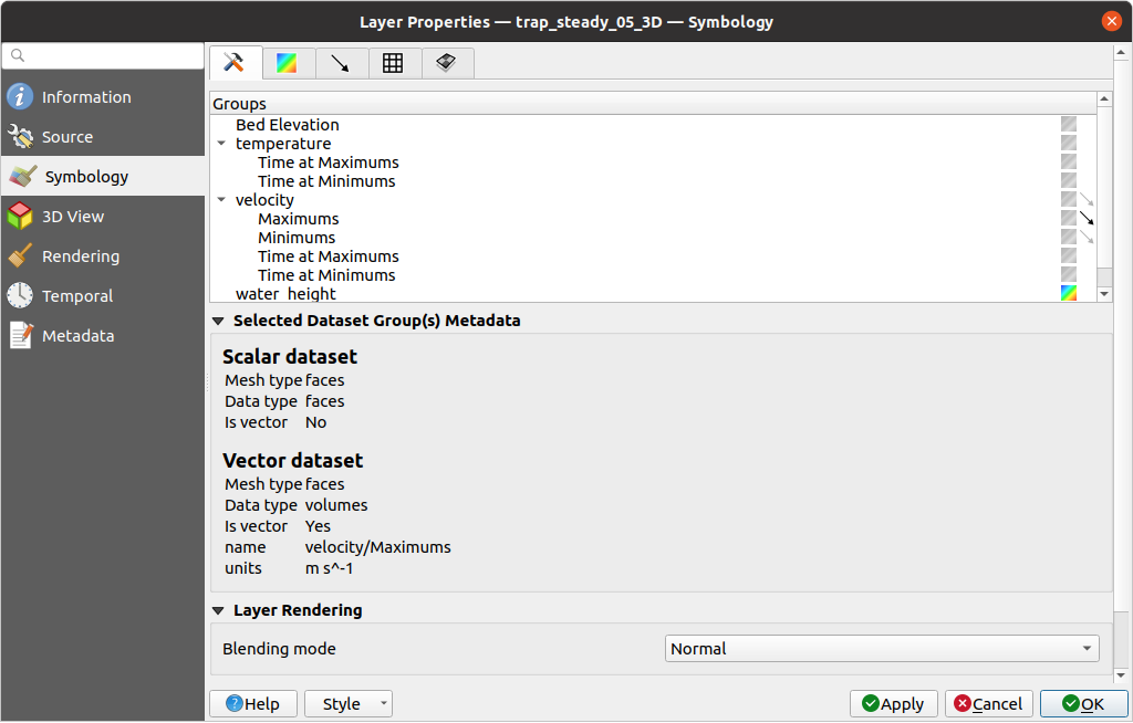
Fig. 14.6 Mesh Layer Datasets
You can apply symbology to the selected vector and/or scalar group using the next tabs.
14.3.3.2. Contours Symbology
Note
The  Contours tab can be activated only if a
scalar dataset has been selected in the
  Datasets tab.
In the  Contours tab you can see and change the current
visualization options of contours for the selected group, as shown in
Fig. 14.7 below:
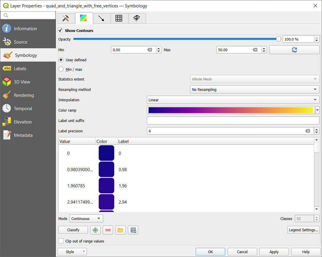
Fig. 14.7 Styling Contours in a Mesh Layer
For 1D mesh, set the Stroke width of the edges. This can be a fixed size for the whole dataset, or vary along the geometry (more details with the interpolated line renderer)
Use the slider or the spinbox to set the Opacity of the current group, if of a 2D mesh type.
 User Defined allows you to enter the range of values you want to represent on the current group:
use
  Load to fetch the min and max values of the current group
or enter custom values if you want to exclude some.
Load to fetch the min and max values of the current group
or enter custom values if you want to exclude some.Select
 Min/Max to set the renderer’s minimum and maximum values based on the chosen extent.
Statictics extent can be Whole mesh, Current canvas or Updated canvas. Updated canvas means that min/max values used for the rendering will change with the canvas extent (dynamic stretching).
For 2D/3D meshes, select the Resampling method to interpolate the values on the surrounding vertices to the faces (or from the surrounding faces to the vertices) using the Neighbour average method. Depending on whether the dataset is defined on the vertices (respectively on the faces), QGIS defaults this setting to None (respectively Neighbour average) method in order to use values on vertices and keep the default rendering smooth.
Classify the dataset using the color ramp shader classification.
14.3.3.3. Vectors Symbology
Note
The  Vectors tab can be activated only if a
vector dataset has been selected in the
  Datasets tab.
Click on the
  Vectors icon on the right side of the
 Datasets tab.
In the  Vectors tab you can see and change the current
visualization options of vectors for the selected group, as shown in
Fig. 14.8:
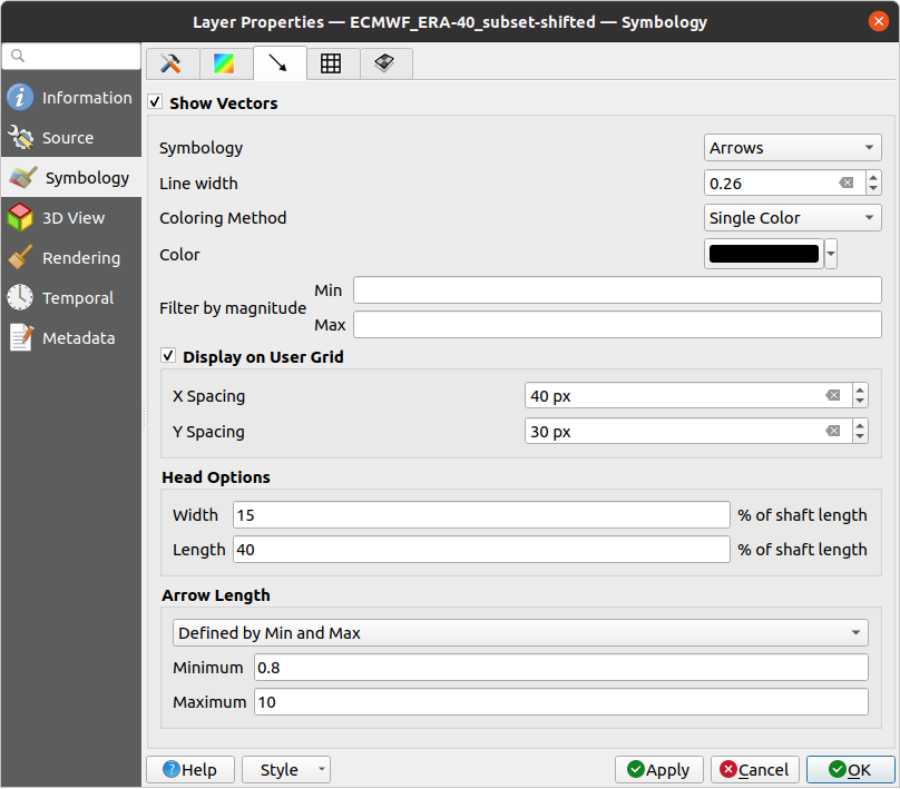
Fig. 14.8 Styling Vectors in a Mesh Layer with arrows
Mesh vector dataset can be styled using various types of Symbology:
Arrows: vectors are represented with arrows at the same place as they are defined in the raw dataset (i.e. on the nodes or center of elements) or on a user-defined grid (hence, they are evenly distributed). The arrow length is proportional to the magnitude of the arrow as defined in the raw data but can be scaled by various methods.
Streamlines: vectors are represented with streamlines seeded from start points. The seeding points can start from the vertices of the mesh, from a user grid or randomly.
Traces: a nicer animation of the streamlines, the kind of effect you get when you randomly throws sand in the water and see where the sand items flows.
Wind barbs: vectors are represented with wind barbs, a common way to represent wind speed and direction.
Available properties depend on the selected symbology as shown in the following table.
Label, Description and Properties |
Arrow |
Streamlines |
Traces |
Wind Barbs |
|---|---|---|---|---|
Line width: Width of the vector representation |
||||
Coloring method:
|
||||
Filter by magnitude: Only vectors whose length for the selected dataset falls between a Min and Max range are displayed |
||||
Display on user grid: Places the vector on a grid with custom X spacing and Y spacing and interpolates their length based on neighbours |
||||
Head options: Length and Width of the arrow head, as a percentage of its shaft length |
||||
Arrow length:
|
||||
Streamlines seeding method:
|
||||
Particles count: The amount of “sand” you want to throw into visualisation |
||||
Max tail length: The time until the particle fades out |
||||
Wind Barbs:
|
14.3.3.4. Rendering
In the tab  Rendering tab, QGIS offers possibilities to
display and customize the mesh structure. Line width and
Line color can be set to represent:
the edges for 1D meshes
For 2D meshes:
Native mesh rendering: shows original faces and edges from the layer
Triangular mesh rendering: adds more edges and displays the faces as triangles
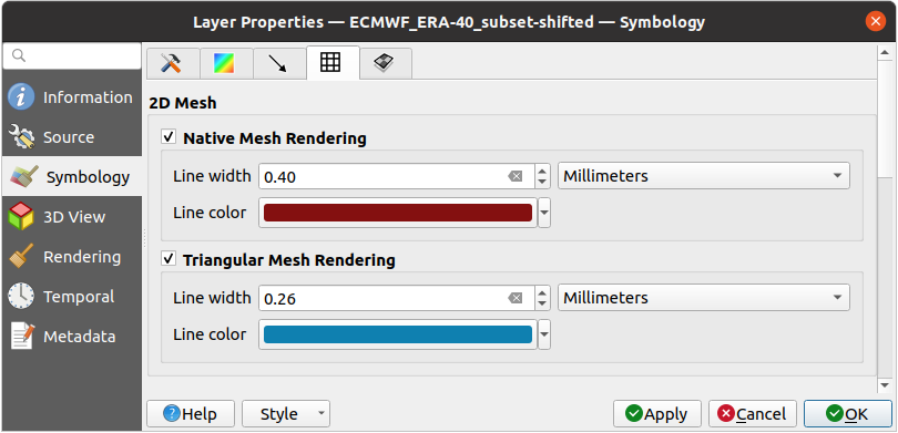
Fig. 14.9 2D Mesh Rendering
14.3.3.5. Stacked mesh averaging method
3D layered meshes consist of multiple stacked 2D unstructured meshes each
extruded in the vertical direction (levels) by means of a vertical
coordinate. The vertices and faces have the same topology in each vertical level.
Values are usually stored on the volumes that are regularly stacked over
base 2d mesh. In order to visualise them on 2D canvas, you need to convert
values on volumes (3d) to values on faces (2d) that can be shown in mesh layer.
The  Stacked mesh averaging method provides different
averaging/interpolation methods to handle this.
You can select the method to derive the 2D datasets and corresponding parameters (level index, depth or height values). For each method, an example of application is shown in the dialog but you can read more on the methods at https://fvwiki.tuflow.com/Depth_Averaging_Results.
14.3.4. Labels Properties
The  Labels tab offers you dynamic labeling of mesh vertices
and native mesh faces based on geometric properties and custom expressions. This
dialog can also be accessed from the Layer Styling panel.
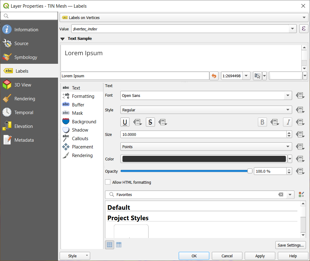
Fig. 14.10 Mesh Labels Properties
Choose the labeling method from the drop-down list. Available methods are:
 No labels: the default value, showing no labels
from the layer.
 Labels on vertices: labels the mesh vertices as a point feature.
 Labels on faces: labels the mesh faces as a polygon feature.
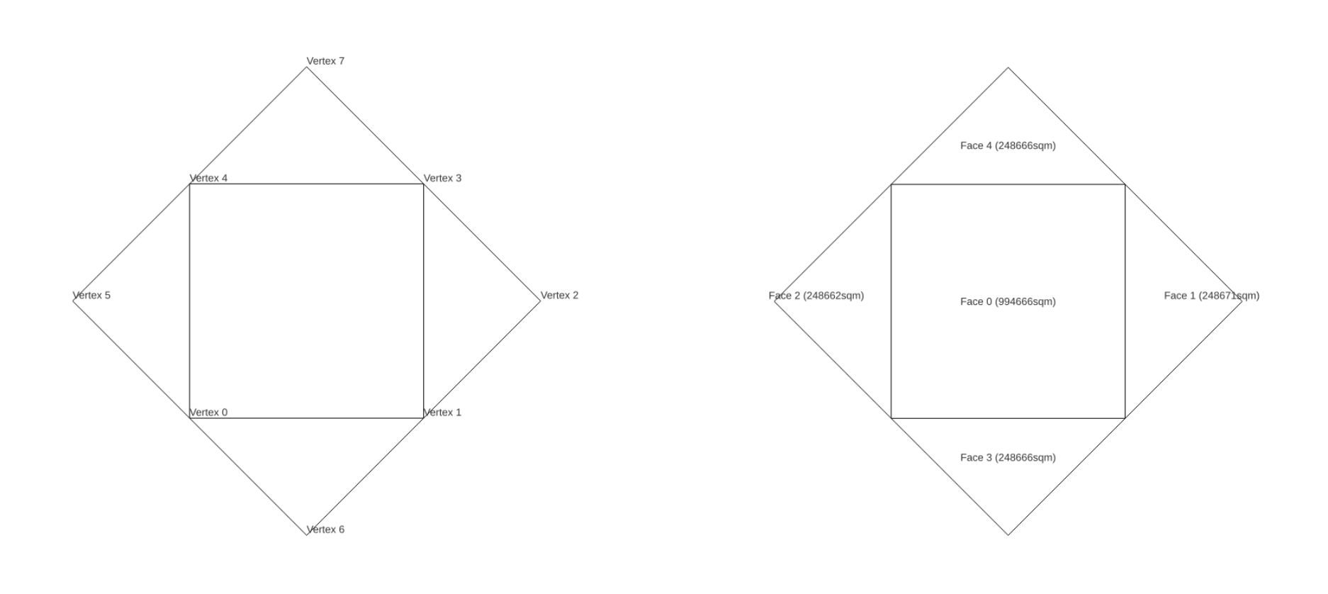
Fig. 14.11 Mesh Labeling methods
Once the labeling method has been selected, open ![]() Expression dialog
and choose a mesh function.
You can combine meshes functions with other functions from the list
to modify the label.
Expression dialog
and choose a mesh function.
You can combine meshes functions with other functions from the list
to modify the label.
Below are displayed options to customize the labels, under various tabs:
Description of how to set each property is exposed at Setting a label.
14.3.5. 3D View Properties
Mesh layers can be used as terrain in a 3D map view
based on their vertices Z values. From the  3D View properties tab,
it’s also possible to render the mesh layer’s dataset in the same 3D view.
Therefore, the vertical component of the vertices can be set equal to dataset
values (for example, level of water surface) and the texture of the mesh can
be set to render other dataset values with color shading (for example velocity).
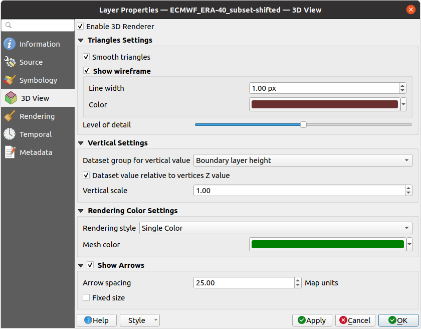
Fig. 14.12 Mesh dataset 3D properties
Check  Enable 3D Renderer and you can edit following
properties:
Under Triangle settings
Smooth triangles: Angles between consecutive triangles are smoothed for a better 3D rendering
Show wireframe whose you can set the Line width and Color
Level of detail: Controls how simplified the mesh layer to render should be. On the far right, it is the base mesh, and the more you go left, the more the layer is simplified and is rendered with less details. This option is only available if the Simplify mesh option under the Rendering tab is activated.
Vertical settings to control behavior of the vertical component of vertices of rendered triangles:
Dataset group for vertical value: the dataset group that will be used for the vertical component of the mesh
 Dataset value relative to vertices Z value: whether
to consider the dataset values as absolute Z coordinate or relative to
the vertices native Z value
Dataset value relative to vertices Z value: whether
to consider the dataset values as absolute Z coordinate or relative to
the vertices native Z valueVertical scale: the scale factor to apply to the dataset Z values
Rendering color settings with a Rendering style that can be based on the color ramp shader set in Contours Symbology (2D contour color ramp shader) or as a Single color with an associated Mesh color
Show arrows: displays arrows on mesh layer dataset 3D entity, based on the same vector dataset group used in the vector 2D rendering. They are displayed using the 2D color setting. It’s also possible to define the Arrow spacing and, if it’s of a Fixed size or scaled on magnitude. This spacing setting defines also the max size of arrows because arrows can’t overlap.
14.3.6. Rendering Properties
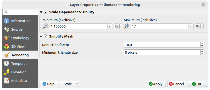
Fig. 14.13 Mesh rendering properties
Under the Scale dependent visibility group box,
you can set the Maximum (inclusive) and Minimum
(exclusive) scale, defining a range of scale in which mesh elements will be
visible. Out of this range, they are hidden. The  Set to current canvas scale button helps you use the current map
canvas scale as boundary of the range visibility.
See Visibility Scale Selector for more information.
Note
You can also activate scale dependent visibility on a layer from within the Layers panel: right-click on the layer and in the contextual menu, select Set Layer Scale Visibility.
As mesh layers can have millions of faces, their rendering can sometimes be very slow, especially when all the faces are displayed in the view whereas they are too small to be viewed. To speed up the rendering, you can simplify the mesh layer, resulting in one or more meshes representing different levels of detail and select at which level of detail you would like QGIS to render the mesh layer. Note that the simplify mesh contains only triangular faces.
From the  Rendering tab, check
  Simplify mesh and set:
a Reduction factor: Controls generation of successive levels of simplified meshes. For example, if the base mesh has 5M faces, and the reduction factor is 10, the first simplified mesh will have approximately 500 000 faces, the second 50 000 faces, the third 5000,… If a higher reduction factor leads quickly to simpler meshes (i.e. with triangles of bigger size), it produces also fewer levels of detail.
Minimum triangle size: the average size (in pixels) of the triangles that is permitted to display. If the average size of the mesh is lesser than this value, the rendering of a lower level of details mesh is triggered.
14.3.7. Temporal Properties
The  Temporal tab provides options to control
the rendering of the layer over time. It allows to dynamically display
temporal values of the enabled dataset groups. Such a dynamic rendering
requires the temporal navigation to be enabled
over the map canvas.
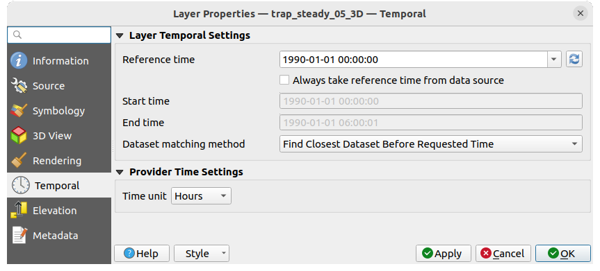
Fig. 14.14 Mesh Temporal properties
Layer temporal settings
Reference time of the dataset group, as an absolute date time. By default, QGIS parses the source layer and returns the first valid reference time in the layer’s dataset group. If unavailable, the value will be set by the project time range or fall back to the current date. The Start time and End time to consider are then calculated based on the internal timestamp step of the dataset.
It is possible to set a custom Reference time (and then the time range), and revert the changes using the
 Reload from provider button.
With
  Always take reference time from data source checked,
you ensure that the time properties are updated from the file
each time the layer is reloaded or the project reopened.
Always take reference time from data source checked,
you ensure that the time properties are updated from the file
each time the layer is reloaded or the project reopened.Dataset matching method: determines the dataset to display at the given time. Options are Find closest dataset before requested time or Find closest dataset from requested time (after or before).
Provider time settings
Time unit extracted from the raw data, or user defined. This can be used to align the speed of the mesh layer with other layers in the project during map time navigation. Supported units are Seconds, Minutes, Hours and Days.
14.3.8. Elevation Properties
The  Elevation tab provides options to control
the layer elevation properties within a 3D map view and 2D map view
and its appearance in the profile tool charts.
Specifically, you can configure how heights from your dataset are interpreted:
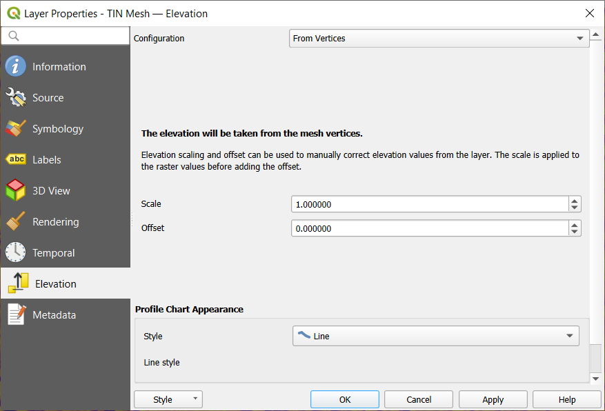
Fig. 14.15 Mesh Elevation properties
From vertices: how the mesh layer vertices Z values should be interpreted as terrain elevation. You can apply a Scale factor and an Offset. This setting is available for 3D map view and profile tool charts.
Fixed Elevation Range: the mesh layer is linked to a fixed elevation range. This mode is applicable when a layer has either a single fixed elevation or a range (slice) of elevation values. If a range is specified, mesh values will be extruded over this range. You can set the Lower and Upper elevation range values for the layer, and specify whether the lower or upper Limits are inclusive or exclusive. When enabled, the layer will only be visible in elevation filtered 2D maps when the layer’s range is included in the map’s Z range.
Fixed Elevation Range Per Group: each group in the mesh layer is associated with a fixed elevation range. This mode can be used when a layer has elevation data exposed through different dataset groups. This feature is exposed as a user-editable table for dataset groups with lower and upper values. You can either populate the lower and upper values manually or use an
 Expression to auto-fill all group values based on an expression.
When enabled, the layer will be filtered in the 2D map view,
displaying only values within the map filter ranges.
In 3D map view or profile tool charts,
the full extent of the layer will be displayed, ignoring the filtering.
Expression to auto-fill all group values based on an expression.
When enabled, the layer will be filtered in the 2D map view,
displaying only values within the map filter ranges.
In 3D map view or profile tool charts,
the full extent of the layer will be displayed, ignoring the filtering.Profile Chart Appearance: controls the rendering of the mesh elements elevation in the profile chart. The profile Style can be set as:
a Line with a specific Line style
an elevation surface rendered using a fill symbol either above (Fill above) or below (Fill below) the elevation curve line. The surface symbology is represented using:
and a Limit: the maximum (respectively minimum) altitude determining how high the fill surface will be
14.3.9. Metadata Properties
The  Metadata tab provides you with options
to create and edit a metadata report on your layer.
See Metadata for more information.
14.3.10. Legend Properties
The  Legend tab provides you with advanced
settings for the Layers panel and/or the print
layout legend. These options include:
Under General settings, uncheck the
 Include automatically in print layout legend items
if you want to hide by default the layer from the print layout legends.
Include automatically in print layout legend items
if you want to hide by default the layer from the print layout legends.The
 Embedded widgets in Legend provides you with a list
of widgets you can embed within the layer tree in the Layers panel.
The idea is to have a way to quickly access some actions that are
often used with the layer (setup transparency, filtering, selection,
style or other stuff…).
Embedded widgets in Legend provides you with a list
of widgets you can embed within the layer tree in the Layers panel.
The idea is to have a way to quickly access some actions that are
often used with the layer (setup transparency, filtering, selection,
style or other stuff…).By default, QGIS provides a transparency widget but this can be extended by plugins that register their own widgets and assign custom actions to layers they manage.
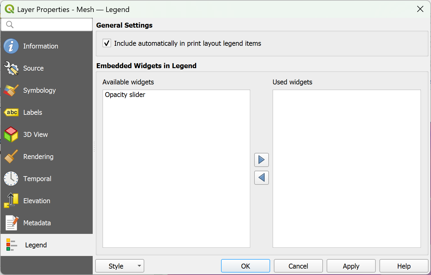
Fig. 14.16 Mesh Legend
14.4. Exploring mesh datasets
To identify mesh elements and their associated datasets, use the
 Identify Features tool from the Attributes toolbar.
Click on a mesh element in the map canvas and the Identify Results panel
opens, displaying information about the mesh layer and the identified element. The panel shows:
Layer name
Active dataset groups (scalar and/or vector) for the clicked element will be displayed first. On the other hand, inactive dataset groups are shown afterwards. For each group, the following derived information may also be shown, if applicable:
Source of the dataset (the file where it is stored).
Time step of the dataset value being displayed. For non-temporal dataset groups, this field remains empty.
Vector x-component and Vector y-component values for vector datasets.
Please note that when temporal navigation is disabled, the results only contain values from the static dataset groups defined.
Geometry information shows the coordinates of the clicked point and may contain derived information in the following:
Centroid of the face.
Coordinates of a snapped vertex (if the click was snapped to a vertex).
Center of a snapped edge (if the click was snapped to an edge).
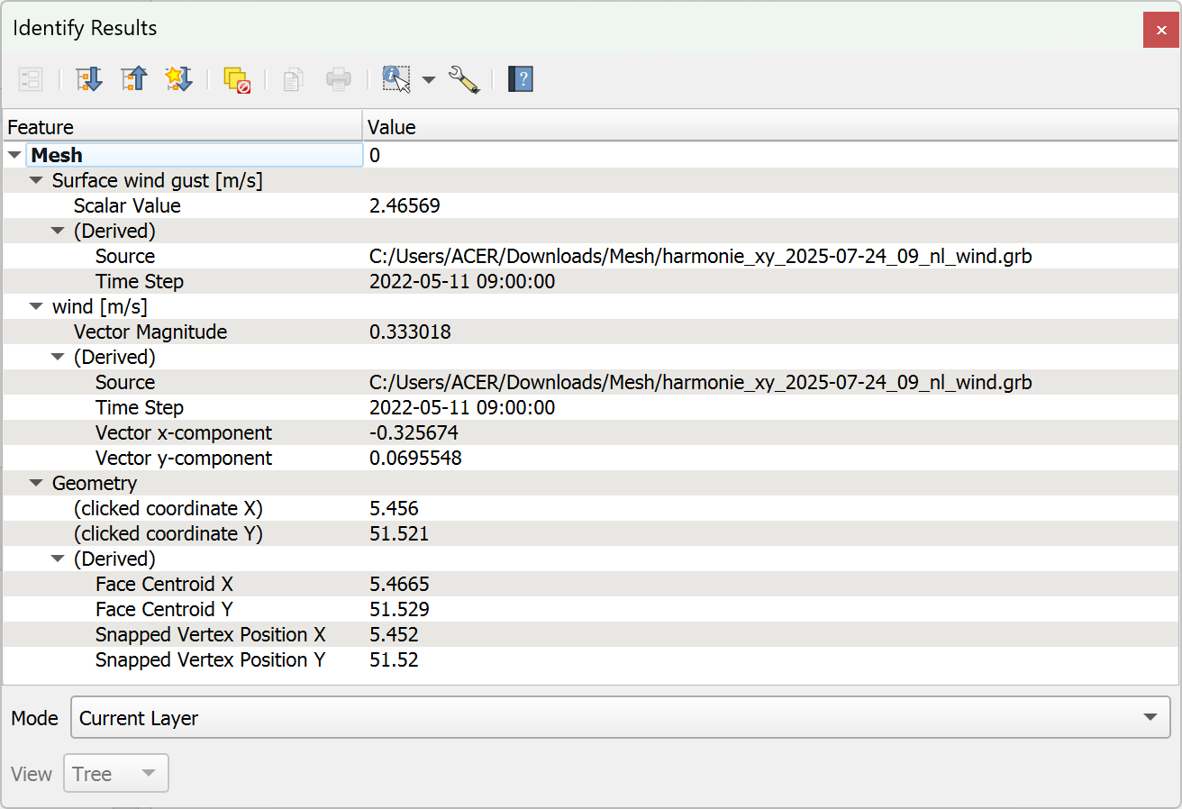
Fig. 14.17 Mesh Identify Results panel
14.5. Editing a mesh layer
QGIS allows to create a mesh layer from scratch or based on an existing one. You can create/modify the geometries of the new layer whom you can assign datasets afterwards. It’s also possible to edit an existing mesh layer. Because the editing operation requires a frames-only layer, you will be asked to either remove any associated datasets first (make sure you have them available if they still are necessary) or create a copy (only geometries) of the layer.
Note
QGIS does not allow to digitize edges on mesh layers. Only vertices and faces are mesh elements that can be created. Also not all supported mesh formats can be edited in QGIS (see permissions).
14.5.1. Overview of the mesh digitizing tools
To interact with or edit a base mesh layer element, following tools are available.
Label |
Purpose |
Location |
|---|---|---|
Access to save, rollback or cancel changes in all or selected layers simultaneously |
Digitizing toolbar |
|
Turn on/off the layer in edit mode |
Digitizing toolbar |
|
Save changes done to the layer |
Digitizing toolbar |
|
Undo the last change(s) - Ctrl+Z |
Digitizing toolbar |
|
Redo the last undone action(s) - Ctrl+Shift+Z |
Digitizing toolbar |
|
Turn on/off the Advanced Digitizing Panel |
Advanced Digitizing toolbar |
|
Recreate index and renumber the mesh elements for optimization |
Mesh menu |
|
Select/Create vertices and faces |
Mesh Digitizing toolbar |
|
Select vertices and faces overlapped by a drawn polygon |
Mesh Digitizing toolbar |
|
Select vertices and faces using an expression |
Mesh Digitizing toolbar |
|
Modify coordinates of a selection of vertices |
Mesh Digitizing toolbar |
|
Split faces and constrain Z value using a linear geometry |
Mesh Digitizing toolbar |
14.5.2. Exploring the Z value assignment logic
When a mesh layer is turned into edit mode, a Vertex Z value widget opens at the top right of the map canvas. By default, its value corresponds to the Default Z value set in tab. When there are selected vertices, the widget displays the average Z value of the selected vertices.
During editing, the Vertex Z value is assigned to new vertices.
It is also possible to set a custom value: edit the widget, press Enter
and you will override the default value and make use of this new value in
the digitizing process.
Click the ![]() icon in the widget to reset its value to the Options
default value.
icon in the widget to reset its value to the Options
default value.
14.5.2.1. Rules of assignment
This is configured in the drop-down menu of the Digitize mesh elements tool as New vertex Z value option. Following methods are available:
Method |
Description |
|---|---|
Project terrain |
Z value is always taken or calculated from the project reference terrain.
|
Z widget |
Z value is taken from the Vertex Z value widget or the Advanced Digitizing Panel Z widget (if it is in Locked state). |
Prefer mesh, then Z widget |
Interpolates the Z value from the active mesh layer if the vertex is on an edge or face, otherwise falls back to the Vertex Z value or Advanced Digitizing Panel Z widget (if it is in Locked state). |
Prefer mesh, then terrain |
Interpolates the Z value from the active mesh layer if the vertex is on the edge or face, otherwise uses the project reference terrain value. |
The following detailed logic describes the behavior of the Prefer mesh, then Z widget strategy.
Vertex creation |
Vertices selected? |
Source of assigned value |
Assigned Z Value |
|---|---|---|---|
“Free” vertex, not connected to any face or edge of a face |
No |
Vertex Z value |
Default or user defined |
Yes |
Vertex Z value |
Average of the selected vertices or user-defined |
|
Vertex on an edge |
— |
Mesh layer |
Interpolated from the edge’s vertices |
Vertex on a face |
— |
Mesh layer |
Interpolated from the face’s vertices |
Vertex snapped to a 2D vector feature |
— |
Vertex Z value |
Default or user defined |
Vertex snapped to a 3D vector vertex |
— |
Vector layer |
Vertex |
Vertex snapped to a 3D vector segment |
— |
Vector layer |
Interpolated along the vector segment |
Note
The Vertex Z value widget is deactivated if the Advanced Digitizing Panel is enabled and no mesh element is selected. The latter’s z widget then rules the Z value assignment.
14.5.2.2. Modifying Z value of existing vertices
To modify the Z value of vertices, the most straightforward way is:
Select one or many vertices. The Vertex Z value widget will display the average height of the selection.
Change the value in the widget.
Press Enter. The entered value is assigned to the vertices and becomes the default value of next vertices.
Another way to change the Z value of a vertex is to move and snap it on a vector layer feature with the Z value capability. If more than one vertex are selected, the Z value can’t be changed in this way.
The Transform mesh vertices dialog also provides means to modify the Z value of a selection of vertices (along with their X or Y coordinates).
14.5.3. Selecting mesh elements
To select mesh elements, you can use the following tools:
 Digitize Mesh Elements to select different mesh elements, see more at Using Digitize Mesh Elements.
 Select Mesh Elements by Polygon to select different mesh elements by polygon,
see more at Using Select Mesh Elements by Polygon.
 Select Mesh Elements by Expression to select different mesh elements by expression,
you can choose to Select by vertices or Select by faces, see more at Using Select Mesh Elements by Expression.
 Select Isolated Vertices to select all vertices that are not part of any mesh face.
 Select All Vertices to select all vertices of the mesh layer.
14.5.3.1. Using Digitize Mesh Elements
Activate the  Digitize Mesh Elements tool.
Hover over an element and it gets highlighted, allowing you to select it.
Click on a vertex, and it is selected.
Click on the small square at the center of a face or an edge, and it gets selected. Connected vertices are also selected. Conversely, selecting all the vertices of an edge or a face also selects that element.
Drag a rectangle to select overlapping elements (a selected face comes with all their vertices). Press Alt key if you want to select only completely contained elements.
To add elements to a selection, press Shift while selecting them.
To remove an element from the selection, press Ctrl and reselect it. A deselected face will also deselect all their vertices.
14.5.3.2. Using Select Mesh Elements by Polygon
Activate the  Select Mesh Elements by Polygon tool and:
Draw a polygon (left-click to add vertex, Backspace to undo last vertex, Esc to abort the polygon and right-click to validate it) over the mesh geometries. Any partially overlapping vertices and faces will get selected. Press Alt key while drawing if you want to select only completely contained elements.
Right-click over the geometry of a vector layer’s feature, select it in the list that pops up and any partially overlapping vertices and faces of the mesh layer will get selected. Use Alt while drawing to select only completely contained elements.
To add elements to a selection, press Shift while selecting them.
To remove an element from the selection, press Ctrl while drawing over the selection polygon.
14.5.3.3. Using Select Mesh Elements by Expression
Another tool for mesh elements selection is  Select Mesh Elements by Expression. When pressed, the tool opens the mesh
expression selector dialog from which you can:
Select the method of selection:
Select by vertices: applies the entered expression to vertices, and returns matching ones and their eventually associated edges/faces
Select by faces: applies the entered expression to faces, and returns matching ones and their associated edges/vertices
Write the expression of selection. Depending on the selected method, available functions in the Meshes group will be filtered accordingly.
Run the query by setting how the selection should behave and pressing:
14.5.4. Modifying mesh elements
14.5.4.1. Adding vertices
To add vertices to a mesh layer:
A Vertex Z value widget is always available on the top right corner of the map canvas during digitizing. It allows setting or overriding the Z coordinate assigned to new vertices, depending on the selected Z value assignment method.
You can choose other method for assigning Z values to new vertices from the drop-down menu in the
 Digitize mesh elements tool.
Then double-click:
outside a face: adds a “free vertex”, that is a vertex not linked to any face. This vertex is represented by a red dot when the layer is in editing mode.
on the edge of existing face(s): adds a vertex on the edge, splits the touching face(s) into triangles connected to the new vertex.
inside a face: splits the face into triangles whose edges connect the surrounding vertices to the new vertex.
With the Refine neighboring faces when adding vertices option enabled in the
 Digitize mesh elements button drop-down menu,
a check is applied to triangular faces that share at least one vertex with the face the new vertex is added to.
If their edges do not satisfy Delaunay triangulation rules, they are flipped accordingly.
14.5.4.2. Adding faces
To add faces to a mesh layer:
A Vertex Z value widget appears on the top right corner of the map canvas. Set this value to the Z coordinate you would like to assign to the subsequent vertices.
Hover over a vertex and click the small triangle that appears next to it.
Move the cursor to the next vertex position; you can snap to existing vertex or left-click to add a new one.
Proceed as above to add as many vertices as you wish for the face. Press Backspace button to undo the last vertex.
While moving the mouse, a rubberband showing the shape of the face is displayed. If it is shown in green, then the expected face is valid and you can right-click to add it to the mesh. If it is red, the face is not valid (e.g. because it self-intersects, overlaps an existing face or vertex, creates a hole, …) and can’t be added. You’d need to undo some vertices and fix the geometry.
Press Esc to abort the face digitizing.
Right-click to validate the face.
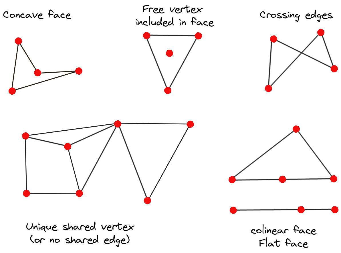
Fig. 14.18 Examples of invalid mesh
14.5.4.3. Removing mesh elements
Right-click and select:
Remove Selected Vertices and Fill Hole(s) or press Ctrl+Del: removes vertices and linked faces and fills the hole(s) by triangulating from the neighbor vertices
Remove Selected Vertices Without Filling Hole(s) or press Ctrl+Shift+Del: removes vertices and linked faces and do not fill hole(s)
Remove Selected Face(s) or press Shift+Del: removes faces but keeps the vertices
These options are also accessible from the contextual menu when hovering over a single item without selecting.
14.5.4.4. Moving mesh elements
To move vertices and faces of a mesh layer:
To start moving the element, click on a vertex or the centroid of a face/edge
Move the cursor to the target location (snapping to vector features is supported).
If the new location does not generate an invalid mesh, the moved elements appear in green. Click again to release them at this location. Faces whose vertices are all selected are translated, their neighbors are reshaped accordingly.
14.5.4.5. Transforming mesh vertices
The  Transform Vertices Coordinates tool gives
a more advanced way to move vertices, by editing their X, Y and/or Z coordinates
thanks to expressions.
Select the vertices you want to edit the coordinates
Press
 Transform Vertices Coordinates.
A dialog opens with a mention of the number of selected vertices.
You can still add or remove vertices from the selection.
Transform Vertices Coordinates.
A dialog opens with a mention of the number of selected vertices.
You can still add or remove vertices from the selection.Depending on the properties you want to modify, you need to check the X coordinate, Y coordinate and/or Z value.
Then enter the target position in the box, either as a numeric value or an expression (using the
 Expression dialog)
With the
 Import Coordinates of the Selected Vertex
pressed, the X, Y and Z boxes are automatically filled with its coordinates
whenever a single vertex is selected. You can adjust Z value by using
 Get the Z value from the project terrain button
and in that case the Z box is deactivated.
A convenient and quick way to adjust vertices individually.
Get the Z value from the project terrain button
and in that case the Z box is deactivated.
A convenient and quick way to adjust vertices individually.Press Preview Transform to simulate the vertices new location and preview the mesh with transformation.
If the preview is green, transformed mesh is valid and you can apply the transformation.
If the preview is red, the transformed mesh is invalid and you can not apply the transformation until it is corrected.
Press Apply Transform to modify the selected coordinates for the set of vertices.
14.5.4.6. Reshaping mesh geometry
The edge markers
When the  Digitize mesh elements is active and you hover
over an edge, the edge is highlighted and it is possible to interact with it.
Depending on the context, following markers may be available:
a square, at the center of the edge: click on it to select extremity vertices.
a cross if the two faces on either side can be merged: click on it to delete the edge and merge the faces.
a circle if the edge is between two triangles: Click on it to flip the edge, i.e. connect it instead to the two other “free” vertices of the faces
The Force by Selected Geometries tool
The  Force by Selected Geometries tool
provides advanced ways to apply break lines using lines geometry.
A break line will force the mesh to have edges along the line. Note that
the break line will not be considered persistent once the operation is done;
resulting edges will not act as constraints anymore and can be modified like
any other edge.
This can be used for example to locally modify a mesh layer with accurate
lines, as river banks or border of road embankments.
Indicate the geometry to use as “forcing line”; it can be:
picked from a line or polygon feature in the map canvas: right-click over the vector feature and select it from the list in the contextual menu.
a virtual line drawn over the mesh frame: left-click to add vertices, right-click for validation. Vertices Z value is set through the Vertex Z value widget or the z widget if the Advanced Digitizing Panel is on. If the line is snapped to a mesh vertex or a 3D vector feature’s vertex or segment, the new vertex takes the snapped element Z value.
Mesh faces that overlap the line geometry or the polygon’s boundary will be
affected in a way that depends on options you can set from
the  Force by Selected
Geometries tool drop-down menu:
 Add new vertex on intersecting edges: with this option,
a new vertex is added each time the forcing line intersect an edge. This option
leads to split along the line each encountered faces.
Add new vertex on intersecting edges: with this option,
a new vertex is added each time the forcing line intersect an edge. This option
leads to split along the line each encountered faces.Without this option, encountered faces are removed and replaced by faces coming from a triangulation with only the existing vertices plus the vertices of the forcing lines (new vertices are also added on the boundary edge intersecting the forcing lines).

Fig. 14.19 Force Mesh using a line geometry - Results without (middle) and with (right) new vertex on edges intersection
Interpolate Z value from: set how the new vertices Z value is calculated. It can be from:
the Mesh itself: the new vertices Z value is interpolated from vertices of the face they fall within
or the Forcing line: if the line is defined by a 3D vector feature or a drawn line then the new vertices Z value is derived from its geometry. In case of 2D line feature, the new vertices Z value is the Vertex Z value.
Tolerance: when an existing mesh vertex is closer to the line than the tolerance value, do not create new vertex on the line but use the existing vertex instead. The value can be set in Meters at Scale or in Map Units (more details at Unit Selector).
14.5.5. Reindexing meshes
During edit, and in order to allow quick undo/redo operations, QGIS keeps empty
places for deleted elements, which may lead to growing memory use and
inefficient mesh structuring.
The  tool is designed to remove these holes and renumber the indices of
faces and vertices so that they are continuous and somewhat reasonably ordered.
This optimizes relation between faces and vertices and increases the efficiency
of calculation.
14.6. Mesh Calculator
The Mesh Calculator tool from the top menu allows you to perform arithmetic and logical calculations on existing dataset groups to generate a new dataset group (see Fig. 14.20).
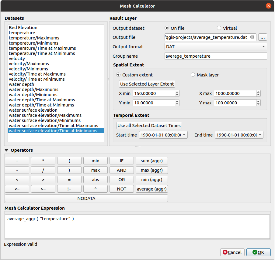
Fig. 14.20 Mesh Calculator
The Datasets list contains all dataset groups in the active mesh layer. To use a dataset group in an expression, double click its name in the list and it will be added to the Mesh calculator expression field. You can then use the operators to construct calculation expressions, or you can just type them into the box.
The Result Layer helps you configure properties of the output layer:
 Create on-the-fly dataset group instead of writing layer
to disk:
Create on-the-fly dataset group instead of writing layer
to disk:If unchecked, the output is stored on disk as a new plain file. An Output File path and an Output Format are required.
If checked, a new dataset group will be added to the mesh layer. Values of the dataset group are not stored in memory but each dataset is calculated when needed with the formula entered in the mesh calculator. That virtual dataset group is saved with the project, and if needed, it can be removed or made persistent in file from the layer Source properties tab.
In either case, you should provide a Group Name for the output dataset group.
The Spatial extent to consider for calculation can be:
defined as a Custom extent using the extent selector widget.
defined by a polygon layer (Mask layer) of the project: the polygon features geometry are used to clip the mesh layer datasets
The Temporal extent to take into account for datasets can be set with the Start time and End time options, selected from the existing dataset groups timesteps. They can also be filled using the Use all selected dataset times button to take the whole range.
With the
 Add result to project checkbox, the result layer
will automatically be added to the legend area and can be visualized.
Checked by default.
The Operators section contains all available operators. To add an operator
to the mesh calculator expression box, click the appropriate button. Mathematical
calculations (+, -, *, … ) and statistical functions (min,
max, sum (aggr), average (aggr), … ) are available.
Conditional expressions (=, !=, <, >=, IF, AND, NOT, … )
return either 0 for false and 1 for true, and therefore can be used with other operators
and functions. The NODATA value can also be used in the expressions.
The Mesh Calculator Expression widget shows and lets you edit the expression to execute.


